EP0342991A1 - Konsolensystem - Google Patents
Konsolensystem Download PDFInfo
- Publication number
- EP0342991A1 EP0342991A1 EP89305067A EP89305067A EP0342991A1 EP 0342991 A1 EP0342991 A1 EP 0342991A1 EP 89305067 A EP89305067 A EP 89305067A EP 89305067 A EP89305067 A EP 89305067A EP 0342991 A1 EP0342991 A1 EP 0342991A1
- Authority
- EP
- European Patent Office
- Prior art keywords
- axis
- bracket
- along
- component
- bracket system
- Prior art date
- Legal status (The legal status is an assumption and is not a legal conclusion. Google has not performed a legal analysis and makes no representation as to the accuracy of the status listed.)
- Withdrawn
Links
- 125000006850 spacer group Chemical group 0.000 claims description 10
- 239000011159 matrix material Substances 0.000 claims description 6
- 230000006835 compression Effects 0.000 claims 2
- 238000007906 compression Methods 0.000 claims 2
- 238000010348 incorporation Methods 0.000 claims 1
- 238000005253 cladding Methods 0.000 abstract description 18
- 238000004519 manufacturing process Methods 0.000 description 6
- 238000010276 construction Methods 0.000 description 5
- 238000000034 method Methods 0.000 description 5
- 230000008901 benefit Effects 0.000 description 4
- 230000003014 reinforcing effect Effects 0.000 description 3
- 229910000831 Steel Inorganic materials 0.000 description 2
- 230000007547 defect Effects 0.000 description 2
- 239000010959 steel Substances 0.000 description 2
- 229910001209 Low-carbon steel Inorganic materials 0.000 description 1
- 238000005452 bending Methods 0.000 description 1
- 238000005266 casting Methods 0.000 description 1
- 230000008602 contraction Effects 0.000 description 1
- 238000009434 installation Methods 0.000 description 1
- 230000002787 reinforcement Effects 0.000 description 1
- 230000003068 static effect Effects 0.000 description 1
Images


Classifications
-
- E—FIXED CONSTRUCTIONS
- E04—BUILDING
- E04F—FINISHING WORK ON BUILDINGS, e.g. STAIRS, FLOORS
- E04F13/00—Coverings or linings, e.g. for walls or ceilings
- E04F13/07—Coverings or linings, e.g. for walls or ceilings composed of covering or lining elements; Sub-structures therefor; Fastening means therefor
- E04F13/08—Coverings or linings, e.g. for walls or ceilings composed of covering or lining elements; Sub-structures therefor; Fastening means therefor composed of a plurality of similar covering or lining elements
- E04F13/0801—Separate fastening elements
- E04F13/0832—Separate fastening elements without load-supporting elongated furring elements between wall and covering elements
- E04F13/0853—Separate fastening elements without load-supporting elongated furring elements between wall and covering elements adjustable perpendicular to the wall
- E04F13/0855—Separate fastening elements without load-supporting elongated furring elements between wall and covering elements adjustable perpendicular to the wall adjustable in several directions, one of which is perpendicular to the wall
-
- E—FIXED CONSTRUCTIONS
- E04—BUILDING
- E04B—GENERAL BUILDING CONSTRUCTIONS; WALLS, e.g. PARTITIONS; ROOFS; FLOORS; CEILINGS; INSULATION OR OTHER PROTECTION OF BUILDINGS
- E04B2/00—Walls, e.g. partitions, for buildings; Wall construction with regard to insulation; Connections specially adapted to walls
- E04B2/88—Curtain walls
- E04B2/90—Curtain walls comprising panels directly attached to the structure
- E04B2/92—Sandwich-type panels
Definitions
- This invention relates to a bracket system, more particularly to a bracket system which is suitable for supporting and positioning components of a building, such as cladding panels.
- the cladding panel is an example of a component which is usually manufactured off-site.
- Cladding panels are designed to be attached to the structure of a building, fitting together to form the walls and thus to produce the external finish of the completed building.
- the panels may be produced complete with windows, doors, radiators and the like and may be of any practicable size, the upper limit being dictated by transport limitations between factory and site. This upper limit is of the order of 6m x 12m, and a panel of that size may weigh six tonnes or more.
- An object of this invention is to provide an improved bracket system which overcomes or mitigates the disadvantages of existing systems.
- a bracket for supporting and positioning a component on a structure in use, the bracket being capable of controlling movement of the component in two directions.
- a bracket system including a plurality of brackets for supporting and positioning a building component on a structure in use, wherein a first bracket is adapted to control movement of the component along a first axis, while permitting movement along a second axis transverse to the first axis, and a second bracket is adapted to control movement of the component along the second axis while permitting movement along the first axis.
- one of the first and second brackets is also adapted to control movement of the component along a third axis transverse to both the first and second axes, and the other of the first and second brackets is also adapted to permit movement along the third axis.
- the first, second and third axes are preferably mutually perpendicular to one another, one axis being vertically aligned and the other axes being horizontally aligned.
- a bracket for supporting and positioning a building component on a structure in use including means for receiving a portion of the component and means for moving or constraining the movement of the component along a first axis while permitting movement of the component along a second axis transverse to the first axis.
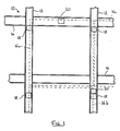
- a structural framework 10 comprises a plurality of spaced vertical columns 12 linked by a plurality of spaced horizontal beams 14 in the usual manner.
- the framework 10 supports, and is enclosed by, a plurality of cladding panels 16.
- the outlines of three cladding panels 16a. 16b and 16c are shown in dotted lines in typical positions; it will be clear that the panels may be of any suitable shape or size and may be positioned in any appropriate position relative to the columns and beams constituting the framework.
- each panel 16 is attached to the framework 10 by a total of three brackets; two of the brackets (18) are identical to one another and are each attached to a column 12, the other bracket (20) is preferably attached to a beam 14 as shown in relation to panel 16a but may be attached to a column 12, as shown in relation to panel 16b, if access to a suitable beam is difficult.
- Brackets 18 preferably bear substantially all of the weight of the panel 16 so as to feed the load directly into the columns 12, although brackets 20 may also bear some load if required.
- Each bracket 18 may help to support two adjacent panels, as shown in relation to panels 16a and 16c.
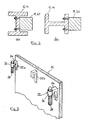
- the members 12,14 constituting the framework 10 are typically of 'I' section; Figure 2(a) shows that a bracket 18,20 may be attached to the web, and Figure 2(b) shows that a bracket may alternatively be attached to the flange of a member if required. It is also possible to attach a bracket 18,20 to a floor slab or to set the bracket into a floor slab, as will be explained.
- Figure 3 shows a panel 16 provided with hooks 22 attached to its upper back surface, by which means the panel may be attached to the framework 10 through brackets 18 and 20.
- the outer hooks 22a for attachment to brackets 18 each include an arm 24 extending perpendicularly from the panel.
- the arm 24 has a threaded sleeve 26 at its free end within which a screw jack member 28 can turn about its longitudinal axis, the jack member being substantially parallel with the back surface of the panel and being threadedly engaged within the sleeve.
- the inner hook 22b for attachment to bracket 20 preferably has a fixed, downwardly depending member instead of a screw jack member 28.
- bracket 18 has a further function i.e. to provide adjustment along the y-axis to allow the panel to be mounted at the correct distance from the framework 10.
- this facility is provided by means of a front plate 38 and a back plate 40, each of which has openings for receiving a pair of threaded rods 42 which extend from the front wall 44 to the rear wall 46 of the body 30.
- the respective ends of rods 42 are suitably located in recesses in the walls 44,46 such that each rod may only be moved angularly about its longitudinal axis.
- the rods 42 are preferably turned about their respective axes by nuts 48 provided at their rear ends, although the rods could alternatively be turned in synchronisation by means such as a common transverse shaft geared to both of the rods.
- the plates 38,40 are held spaced apart by means of a spacer 50 and are caused to move along the rods 42, as the rods are turned, by blocks 52 which are threadedly engaged with the rods.
- the screw jack member 28 of the panel 16 is received in the gap between the plates 38,40 and is thus caused to move with the plates (along the y-axis) when the rods 42 are turned.
- the back plate 40 is similar to front plate 38 but is extended upwardly so that the screw jack member 28 of a panel 16 may be readily positioned within the gap between the plates 38, 40.
- the front plate 38 is covered by an overhanging lip 54 which is shaped to guide the screw jack member into the gap between the plates 38,40; this operation is facilitated by the upwards extension of back plate 40.
- the rods 42 may be turned to wind the plates 38,40 and the panel 16, into the desired position.
- the gap between the plates 38,40 is elongated and is suitable for receiving two hooks 22. This may be required when two panels 16 are positioned beside one another, the panels sharing a bracket 18 as shown in Figure 1. Moreover, the hook or hooks 22 are free to move along the x-axis within the gap.
- Bracket 20 illustrates a possible arrangement for bracket 20, which is broadly similar to bracket 18 but which performs only one main function i.e. to provide horizontal movement, along the x-axis, across the face of the framework 10.
- bracket 20 includes two pairs of threaded rods 56 which are similar to the rods 42 in brackets 18 but are instead arranged parallel to the face of the framework 10.
- the pairs of rods 56 are arranged in different but parallel planes, one pair above the other, and each pair of rods carries an elongate plate 58.
- the rods 56 of each pair are threadedly engaged with respective ends of each plate 58 so that, when the rods of a pair are turned, the associated plate is caused to move along the rods.
- the two plates 58 in bracket 20 may thus be positioned to define a gap therebetween for receiving a hook 22 of a panel 16, and the hook and the panel may be moved along the x-axis by advancing one of the plates and withdrawing the other.
- each pair of rods has a common transverse shaft 60, each shaft being geared to both rods of its associated pair to turn the rods in synchronisation. It is preferred that each shaft 60 includes worm gears which mesh with worm wheels on the associated rods 56. Each shaft 60 is preferably turned by means of a nut located at the rear end of the shaft in an accessible position.
- Bracket 18 A modified arrangement of bracket 18 is shown in Figures 8 and 9.
- the layout of bracket 18 is broadly similar to the arrangement shown in Figures 4 and 5 and common reference numerals are used where appropriate.
- the bracket 18 comprises an open-topped body 30 having a lower wall 34, a front wall 44 and a rear wall 46.
- the body contains a front plate 38, a back plate 40, plastic spacer tubes 50 and blocks 52, all of which are movable along a pair of threaded rods 42.
- the arm 24 of hook 22a comprises a double box section for stiffness and lightness.
- the arm 24 contains a tubular sleeve 62, which has an internally-threaded plate 64 fixed at its upper end.
- the plate 64 could be a welded-in nut.
- the bolt 66 is coaxial with the sleeve 62 and is threadedly engaged within the plate 64, so as to move axially when turned by use of an exposed hexagonal head 68.
- the end of the bolt 66 within the sleeve 62 abuts a cylindrical spacer block 70 which in turn abuts a cylindrical steel pin 72.
- the spacer block 70 and the pin 72 are a close but sliding fit within the sleeve 62.
- the spacer block 70 reduces the slenderness ratio of the bolt 66.
- the pin 72 is supported by the lower wall 34 of bracket 18 in the manner of the screw jack member 28 of Figures 4 and 5.
- the spacer block 70 can be used for coarse adjustment of height (along the z-axis) so that if the cladding panel 16 is too low, spacers can be added to the block 70. Conversely, if the panel 16 is too high, spacers can be taken away from the block 70. Fine z-axis adjustment may still be made by using the bolt 66, the spacer block 70 simply reducing the length of time needed to complete adjustment.
- brackets 8 and 9 Another significant feature of the bracket shown in Figures 8 and 9 is the intermediate wall 74, which defines a well 76 within the body 30.
- the nuts 48 used to turn the threaded rods 42 are set into the well 76 and are readily accessible from within the building.
- the front ends of the threaded rods 42 have additional nuts 78 which are accessible from outside the building if necessary.
- Figures 8 and 9 also show that a bracket may be attached to a concrete floor slab 80 instead of a beam or column.
- the bracket 18 illustrated is set into the floor slab 80 between columns during the concrete pouring operation.
- reinforcing rods 82 are attached to the bracket 18 to strengthen the fixing between the bracket 18 and the concrete matrix.
- the bracket 18 may be attached to a cured concrete floor slab by means of bolts extending through the lower wall 34.
- the arrangement shown in Figures 8 and 9 could be adapted for attachment to a beam or to a column, as previously described.
- bracket 18 is downwardly extended and that the reinforcing rods 82 are attached to the rear wall 46 above its centre. This arrangement converts bending forces into tensile forces along the reinforcing rods 82, when the bracket 18 is loaded. Moreover, the extended rear wall 46 acts to compress the concrete matrix. Thus, the bracket 18 of this invention converts a (vertical) load applied across the slab into a (horizontal) load directed through the slab, to the benefit of the slab's load capacity.
- the bracket 18 may be set flush with an edge of the concrete floor slab 74 as shown in Figures 8, 9 an 11(b), or may be cantilevered as shown in Figure (11a).
- bracket 20 provides accurate positioning and firm support for the panel 16 along the x-axis, while allowing substantially free movement along the z- and y-axes.
- bracket 18 allows movement along the x-axis but constrains the panel 16 against movement along the z- and y-axes. The panel 16 can therefore be accurately placed in three dimensions, and can be firmly supported in a given position, by adjustment of the brackets 18 and 20.
- the three brackets 18, 20 of the embodiments described provide most support for the upper part of the panel 16. It is proposed that five brackets may be used on each panel of the lowest row of panels of a building, a further two brackets 18 being located towards the bottom of the panel to provide additional support for the lower part of the panel. Each panel in the rows above may then be linked to the panel immediately below so that the lower part of each panel is supported. This linking may be accomplished by any appropriate means, for example by means of engagement of a pin provided on an upper panel within a recess provided in a lower panel.
- bracket 20 can be replaced by a fixing which connects the back of a panel 16 to the framework 10 or to a floor member or the like.
- the fixing prevents movement along the x-axis while allowing movement along the y- and z-axes.
- the panel 16 can be positioned before being fixed using either a winch or a hydraulic jack to move the panel across the face of the framework 10.
Landscapes
- Engineering & Computer Science (AREA)
- Architecture (AREA)
- Civil Engineering (AREA)
- Structural Engineering (AREA)
- Physics & Mathematics (AREA)
- Electromagnetism (AREA)
- Conveying And Assembling Of Building Elements In Situ (AREA)
Applications Claiming Priority (2)
| Application Number | Priority Date | Filing Date | Title |
|---|---|---|---|
| GB8811833 | 1988-05-19 | ||
| GB888811833A GB8811833D0 (en) | 1988-05-19 | 1988-05-19 | Bracket system |
Publications (1)
| Publication Number | Publication Date |
|---|---|
| EP0342991A1 true EP0342991A1 (de) | 1989-11-23 |
Family
ID=10637148
Family Applications (1)
| Application Number | Title | Priority Date | Filing Date |
|---|---|---|---|
| EP89305067A Withdrawn EP0342991A1 (de) | 1988-05-19 | 1989-05-18 | Konsolensystem |
Country Status (3)
| Country | Link |
|---|---|
| US (1) | US5067292A (de) |
| EP (1) | EP0342991A1 (de) |
| GB (1) | GB8811833D0 (de) |
Cited By (7)
| Publication number | Priority date | Publication date | Assignee | Title |
|---|---|---|---|---|
| FR2668523A1 (fr) * | 1990-10-31 | 1992-04-30 | Laurent Olivier | Dispositif de fixation d'un revetement de facade. |
| GB2266544A (en) * | 1992-05-01 | 1993-11-03 | Kioritz Corp | Vechicle parking structure |
| EP0701896A1 (de) * | 1993-03-11 | 1996-03-20 | Sumitomo Light Metal Industries, Ltd. | Vorgehängte Fassade in wabenförmiger Elementbauweise und wabenförmige Fassadenplatte für diese Fassade |
| EP1785546A1 (de) * | 2005-10-15 | 2007-05-16 | HALFEN GmbH & CO. Kommanditgesellschaft | Konsolanker zur Fixierung einer Verblendung an einer Gebäudewand |
| EP2397622A1 (de) * | 2010-03-09 | 2011-12-21 | H.J.J. Evers Beheer B.V. | Klammeranordnung für eine Fassadenabstützung, Fassadenabstützung, Fassade und Verfahren zu deren Anbringung |
| WO2012136731A1 (de) * | 2011-04-05 | 2012-10-11 | Riessler Markus | Wandverkleidungssystem |
| NL1040337C2 (nl) * | 2013-08-15 | 2015-02-19 | Haase Holding B V W | Bevestigingsmiddelen en werkwijze voor het bevestigen van een prefab bouwelement aan een draagstructuur. |
Families Citing this family (21)
| Publication number | Priority date | Publication date | Assignee | Title |
|---|---|---|---|---|
| DE9216236U1 (de) * | 1992-04-11 | 1993-01-28 | fischerwerke Artur Fischer GmbH & Co KG, 7244 Waldachtal | Konsole für Fassadenbefestigung |
| US6594962B2 (en) * | 2001-06-22 | 2003-07-22 | William Pardue | Method and apparatus for mounting a pre-cast panel to a structure |
| MXPA02000853A (es) * | 2002-01-23 | 2003-07-30 | De Leon Fierro Rigoberto | Paredes con losetas machihembradas y estructura metalica para multiples usos como piso, pared, barda y gradas. |
| US20070039258A1 (en) * | 2005-08-19 | 2007-02-22 | Walker John R Iii | Adjustable attachment system |
| US7987644B2 (en) | 2006-09-15 | 2011-08-02 | Enclos Corporation | Curtainwall system |
| US7681366B2 (en) * | 2007-03-15 | 2010-03-23 | Permasteelisa Cladding Technologies, L.P. | Curtain wall anchor system |
| US7793476B2 (en) * | 2007-10-12 | 2010-09-14 | Sanders Steven H | Non-top supported fence installation bracket |
| US20100257812A1 (en) * | 2009-04-13 | 2010-10-14 | Schultz Christopher A | Adjustable Attachment System |
| KR100984339B1 (ko) * | 2010-05-04 | 2010-09-30 | 나태용 | 커튼월 고정용 가변형 화스너 |
| US8555577B2 (en) | 2011-11-09 | 2013-10-15 | Bellcomb, Inc. | Panel mounting system and method |
| WO2014078437A1 (en) * | 2012-11-13 | 2014-05-22 | Dirtt Environmental Solutions Inc. | Selectively adjustable architectural wall |
| US9016013B2 (en) | 2012-11-20 | 2015-04-28 | Specified Technologies Inc. | Curtain wall anchor fire protection apparatus |
| US8955285B2 (en) * | 2012-12-07 | 2015-02-17 | Illinois Tool Works Inc. | Embedment attachment system |
| JP6250929B2 (ja) * | 2012-12-26 | 2017-12-20 | 大和ハウス工業株式会社 | 外壁構造 |
| US9487960B2 (en) | 2014-06-17 | 2016-11-08 | One Energy Enterprises Llc | Suspended deck systems, kits, and methods of installing, inspecting, and repairing a suspended deck system |
| JP6441049B2 (ja) * | 2014-11-28 | 2018-12-19 | 大和ハウス工業株式会社 | 外壁パネルの固定構造 |
| GB201616976D0 (en) * | 2016-10-06 | 2016-11-23 | Monminy Marcel | Device for spacing and anchoring bulding blocks and a method of using same |
| US10202755B2 (en) * | 2016-10-06 | 2019-02-12 | Technologie 2000 Inc. | Construction block anchoring system |
| JP6740082B2 (ja) * | 2016-10-20 | 2020-08-12 | Ykk Ap株式会社 | 外付け部材の取付構造 |
| EP4536915A1 (de) * | 2022-06-09 | 2025-04-16 | Saint-Gobain Isover | Befestigungssystem für ein fassadenelement und verfahren zu dessen befestigung |
| US12286798B2 (en) * | 2022-06-24 | 2025-04-29 | Blox, Llc | Three axis clip system for mounting panels to a wall |
Citations (10)
| Publication number | Priority date | Publication date | Assignee | Title |
|---|---|---|---|---|
| FR1395895A (fr) * | 1963-04-09 | 1965-04-16 | Panneau préfabriqué permettant de constituer un mur de bâtiment | |
| GB1166924A (en) * | 1966-04-30 | 1969-10-15 | Heinz Schurmann & Co | A fixing and adjusting device for constructional elements |
| DE1683160A1 (de) * | 1968-02-07 | 1971-01-21 | Hans Kopatsch | Platte zur Verkleidung von und zur Befestigung an Waenden |
| DE2221762A1 (de) * | 1972-05-04 | 1973-11-15 | Fricker Frimeda Metall Draht | Fassadenplattenanker |
| DE2246888A1 (de) * | 1972-09-23 | 1974-04-04 | Hans-Joachim Kurz | Vorrichtung zur befestigung von fassadenplatten an gebaeuden |
| DE2428754A1 (de) * | 1974-06-14 | 1975-12-18 | Spannbetonwerk Koch Kg | Vorrichtung zum befestigen von wandplatten an tragenden stuetzen |
| DE2530595A1 (de) * | 1975-07-09 | 1977-01-27 | Willi Clavey | Befestigungsvorrichtung einer fassadenplatte an einem baukoerper |
| DE1683167B2 (de) * | 1966-01-11 | 1977-10-20 | Fa. Karl Lutz, 6980 Wertheim | Wandverkleidung fuer aussenwaende |
| FR2387329A1 (fr) * | 1977-04-12 | 1978-11-10 | Gen Batiment | Systeme de construction d'une facade de batiment a l'aide de panneaux de beton prefabriques |
| DE3405254A1 (de) * | 1984-02-15 | 1985-08-22 | Gerhard Dipl.-Ing. 6478 Nidda Schmollack | Vorrichtung zum befestigen von wandbekleidungselementen |
Family Cites Families (8)
| Publication number | Priority date | Publication date | Assignee | Title |
|---|---|---|---|---|
| GB1026795A (en) * | 1963-04-09 | 1966-04-20 | Robert Charles Rolland | Building wall made from prefabricated panels |
| US3913287A (en) * | 1969-01-23 | 1975-10-21 | Jr Roger S Chapman | Structural system |
| DE2364370A1 (de) * | 1973-12-22 | 1975-06-26 | Lutz Fa Karl | Vorrichtung zur einstellbaren, abstandhaltenden aufhaengung eines verkleidenden bauteils an einem tragenden, ortsfesten bauwerksteil |
| US4070835A (en) * | 1976-08-09 | 1978-01-31 | Safama | Device intended for the hooking of panels on a wall in order to constitute a covering on this wall |
| US4060951A (en) * | 1976-09-15 | 1977-12-06 | Sandor Gere | Stressless suspension and anchoring process of stone veneer |
| SU720114A1 (ru) * | 1977-11-09 | 1980-03-05 | Киевский Зональный Научно-Исследовательский И Проектный Институт Типового И Экспериментального Проектирования Жилых И Общественных Зданий | Устройство дл креплени стеновых панелей |
| US4307551A (en) * | 1979-08-09 | 1981-12-29 | Ppg Industries, Inc. | System for cladding building exteriors |
| US4782635A (en) * | 1987-07-20 | 1988-11-08 | Rockwin Corporation | Connector for hanging panels to a building frame |
-
1988
- 1988-05-19 GB GB888811833A patent/GB8811833D0/en active Pending
-
1989
- 1989-05-18 EP EP89305067A patent/EP0342991A1/de not_active Withdrawn
- 1989-05-19 US US07/354,620 patent/US5067292A/en not_active Expired - Fee Related
Patent Citations (10)
| Publication number | Priority date | Publication date | Assignee | Title |
|---|---|---|---|---|
| FR1395895A (fr) * | 1963-04-09 | 1965-04-16 | Panneau préfabriqué permettant de constituer un mur de bâtiment | |
| DE1683167B2 (de) * | 1966-01-11 | 1977-10-20 | Fa. Karl Lutz, 6980 Wertheim | Wandverkleidung fuer aussenwaende |
| GB1166924A (en) * | 1966-04-30 | 1969-10-15 | Heinz Schurmann & Co | A fixing and adjusting device for constructional elements |
| DE1683160A1 (de) * | 1968-02-07 | 1971-01-21 | Hans Kopatsch | Platte zur Verkleidung von und zur Befestigung an Waenden |
| DE2221762A1 (de) * | 1972-05-04 | 1973-11-15 | Fricker Frimeda Metall Draht | Fassadenplattenanker |
| DE2246888A1 (de) * | 1972-09-23 | 1974-04-04 | Hans-Joachim Kurz | Vorrichtung zur befestigung von fassadenplatten an gebaeuden |
| DE2428754A1 (de) * | 1974-06-14 | 1975-12-18 | Spannbetonwerk Koch Kg | Vorrichtung zum befestigen von wandplatten an tragenden stuetzen |
| DE2530595A1 (de) * | 1975-07-09 | 1977-01-27 | Willi Clavey | Befestigungsvorrichtung einer fassadenplatte an einem baukoerper |
| FR2387329A1 (fr) * | 1977-04-12 | 1978-11-10 | Gen Batiment | Systeme de construction d'une facade de batiment a l'aide de panneaux de beton prefabriques |
| DE3405254A1 (de) * | 1984-02-15 | 1985-08-22 | Gerhard Dipl.-Ing. 6478 Nidda Schmollack | Vorrichtung zum befestigen von wandbekleidungselementen |
Cited By (8)
| Publication number | Priority date | Publication date | Assignee | Title |
|---|---|---|---|---|
| FR2668523A1 (fr) * | 1990-10-31 | 1992-04-30 | Laurent Olivier | Dispositif de fixation d'un revetement de facade. |
| GB2266544A (en) * | 1992-05-01 | 1993-11-03 | Kioritz Corp | Vechicle parking structure |
| GB2266544B (en) * | 1992-05-01 | 1995-10-04 | Kioritz Corp | Vehicle parking structure |
| EP0701896A1 (de) * | 1993-03-11 | 1996-03-20 | Sumitomo Light Metal Industries, Ltd. | Vorgehängte Fassade in wabenförmiger Elementbauweise und wabenförmige Fassadenplatte für diese Fassade |
| EP1785546A1 (de) * | 2005-10-15 | 2007-05-16 | HALFEN GmbH & CO. Kommanditgesellschaft | Konsolanker zur Fixierung einer Verblendung an einer Gebäudewand |
| EP2397622A1 (de) * | 2010-03-09 | 2011-12-21 | H.J.J. Evers Beheer B.V. | Klammeranordnung für eine Fassadenabstützung, Fassadenabstützung, Fassade und Verfahren zu deren Anbringung |
| WO2012136731A1 (de) * | 2011-04-05 | 2012-10-11 | Riessler Markus | Wandverkleidungssystem |
| NL1040337C2 (nl) * | 2013-08-15 | 2015-02-19 | Haase Holding B V W | Bevestigingsmiddelen en werkwijze voor het bevestigen van een prefab bouwelement aan een draagstructuur. |
Also Published As
| Publication number | Publication date |
|---|---|
| US5067292A (en) | 1991-11-26 |
| GB8811833D0 (en) | 1988-06-22 |
Similar Documents
| Publication | Publication Date | Title |
|---|---|---|
| US5067292A (en) | Bracket system | |
| US20100115860A1 (en) | Girder element for concrete formwork comprising a structure for automatically compensating bending strains | |
| KR20220100474A (ko) | 교량의 슬래브 타설 공법 | |
| CN111206768B (zh) | 一种轻型梁板结构平台及其施工方法 | |
| CN115405115A (zh) | 一种可滑移拼装胎架及应用方法 | |
| CN220394851U (zh) | 一种用于装配式梁柱的牛角支撑组件及连接结构 | |
| CN118029703A (zh) | 一种建筑模架施工方法 | |
| CN216329090U (zh) | 一种高效率高精度钢筋定位可调胎架装置 | |
| CN213233165U (zh) | 桥梁辅助墩支座安装装置 | |
| CN212772785U (zh) | 一种装配式建筑用单元式外墙板安装模块 | |
| CN212295097U (zh) | 螺栓安装固定架 | |
| CN109235871A (zh) | 变截面结构铝合金模板施工方法 | |
| CN113550233A (zh) | 一种桥梁用三角托架结构及其施工方法 | |
| CN223256456U (zh) | 一种标高不同的梁柱节点用可调式钢模装置 | |
| CN221029614U (zh) | 可调节装配式钢锚梁支架 | |
| KR102846898B1 (ko) | C-스터드 경량 건축모듈 | |
| CN220789460U (zh) | 一种小箱梁调整顶升架 | |
| KR100278767B1 (ko) | 보 성형용 거푸집 및 이를 이용한 건축물 시공방법 | |
| CN219219508U (zh) | 一种钢筋桁架组合楼板 | |
| CN117822787B (zh) | 一种核电站超厚型现浇钢板混凝土结构及施工方法 | |
| CN218479528U (zh) | 一种钢结构建筑混凝土墙板的组合支模体系 | |
| CN116007574B (zh) | 一种可调轨道式箱梁防撞墙标高的测量方法 | |
| CN223838281U (zh) | 一种杯口柱快速安装施工体系 | |
| JP3244102U (ja) | スチールハウスの基礎構造およびそれに用いるアンカーセット | |
| CN220954534U (zh) | 一种基于bim的高空超长悬挑支撑体系 |
Legal Events
| Date | Code | Title | Description |
|---|---|---|---|
| PUAI | Public reference made under article 153(3) epc to a published international application that has entered the european phase |
Free format text: ORIGINAL CODE: 0009012 |
|
| AK | Designated contracting states |
Kind code of ref document: A1 Designated state(s): AT BE CH DE ES FR GB GR IT LI LU NL SE |
|
| 17P | Request for examination filed |
Effective date: 19900523 |
|
| 17Q | First examination report despatched |
Effective date: 19910607 |
|
| STAA | Information on the status of an ep patent application or granted ep patent |
Free format text: STATUS: THE APPLICATION IS DEEMED TO BE WITHDRAWN |
|
| 18D | Application deemed to be withdrawn |
Effective date: 19911203 |