EP0341894B1 - Bildaufzeichnungsgerät - Google Patents
Bildaufzeichnungsgerät Download PDFInfo
- Publication number
- EP0341894B1 EP0341894B1 EP89304461A EP89304461A EP0341894B1 EP 0341894 B1 EP0341894 B1 EP 0341894B1 EP 89304461 A EP89304461 A EP 89304461A EP 89304461 A EP89304461 A EP 89304461A EP 0341894 B1 EP0341894 B1 EP 0341894B1
- Authority
- EP
- European Patent Office
- Prior art keywords
- developer
- developing sleeve
- bar
- magnetic
- regulating
- Prior art date
- Legal status (The legal status is an assumption and is not a legal conclusion. Google has not performed a legal analysis and makes no representation as to the accuracy of the status listed.)
- Expired - Lifetime
Links
- 230000005291 magnetic effect Effects 0.000 claims description 84
- 230000001105 regulatory effect Effects 0.000 claims description 82
- 238000003825 pressing Methods 0.000 claims description 35
- 238000011161 development Methods 0.000 claims description 22
- 239000000696 magnetic material Substances 0.000 claims description 8
- 239000000463 material Substances 0.000 description 27
- 238000002474 experimental method Methods 0.000 description 18
- 229910001220 stainless steel Inorganic materials 0.000 description 17
- 239000010935 stainless steel Substances 0.000 description 16
- 108091008695 photoreceptors Proteins 0.000 description 15
- 230000005389 magnetism Effects 0.000 description 13
- 229920001971 elastomer Polymers 0.000 description 12
- 239000005060 rubber Substances 0.000 description 12
- 239000002245 particle Substances 0.000 description 11
- 238000000034 method Methods 0.000 description 9
- 229910052751 metal Inorganic materials 0.000 description 8
- 239000002184 metal Substances 0.000 description 8
- 229920005989 resin Polymers 0.000 description 7
- 239000011347 resin Substances 0.000 description 7
- XEEYBQQBJWHFJM-UHFFFAOYSA-N Iron Chemical compound [Fe] XEEYBQQBJWHFJM-UHFFFAOYSA-N 0.000 description 6
- VYPSYNLAJGMNEJ-UHFFFAOYSA-N Silicium dioxide Chemical group O=[Si]=O VYPSYNLAJGMNEJ-UHFFFAOYSA-N 0.000 description 6
- 229910052782 aluminium Inorganic materials 0.000 description 5
- XAGFODPZIPBFFR-UHFFFAOYSA-N aluminium Chemical compound [Al] XAGFODPZIPBFFR-UHFFFAOYSA-N 0.000 description 5
- 230000000694 effects Effects 0.000 description 5
- 230000004907 flux Effects 0.000 description 5
- 239000006247 magnetic powder Substances 0.000 description 5
- 239000004417 polycarbonate Substances 0.000 description 5
- 229920000515 polycarbonate Polymers 0.000 description 5
- 230000007423 decrease Effects 0.000 description 4
- 239000013013 elastic material Substances 0.000 description 4
- 238000007689 inspection Methods 0.000 description 4
- 150000002739 metals Chemical class 0.000 description 4
- 238000005192 partition Methods 0.000 description 4
- -1 phenolic resin Chemical class 0.000 description 4
- 229920006311 Urethane elastomer Polymers 0.000 description 3
- 238000004220 aggregation Methods 0.000 description 3
- 230000002776 aggregation Effects 0.000 description 3
- 239000003795 chemical substances by application Substances 0.000 description 3
- 230000007547 defect Effects 0.000 description 3
- 239000006260 foam Substances 0.000 description 3
- 229910052742 iron Inorganic materials 0.000 description 3
- 238000012423 maintenance Methods 0.000 description 3
- 230000007246 mechanism Effects 0.000 description 3
- 229920000728 polyester Polymers 0.000 description 3
- 230000008569 process Effects 0.000 description 3
- 239000004576 sand Substances 0.000 description 3
- 229920002379 silicone rubber Polymers 0.000 description 3
- 230000003746 surface roughness Effects 0.000 description 3
- 229910000859 α-Fe Inorganic materials 0.000 description 3
- VTYYLEPIZMXCLO-UHFFFAOYSA-L Calcium carbonate Chemical compound [Ca+2].[O-]C([O-])=O VTYYLEPIZMXCLO-UHFFFAOYSA-L 0.000 description 2
- 229910000640 Fe alloy Inorganic materials 0.000 description 2
- 239000002253 acid Substances 0.000 description 2
- 229910045601 alloy Inorganic materials 0.000 description 2
- 239000000956 alloy Substances 0.000 description 2
- 230000033228 biological regulation Effects 0.000 description 2
- 230000000903 blocking effect Effects 0.000 description 2
- 230000015556 catabolic process Effects 0.000 description 2
- 239000000919 ceramic Substances 0.000 description 2
- 230000003247 decreasing effect Effects 0.000 description 2
- 238000006731 degradation reaction Methods 0.000 description 2
- 230000006866 deterioration Effects 0.000 description 2
- 238000005516 engineering process Methods 0.000 description 2
- 230000007613 environmental effect Effects 0.000 description 2
- 239000005038 ethylene vinyl acetate Substances 0.000 description 2
- 239000011521 glass Substances 0.000 description 2
- RBTKNAXYKSUFRK-UHFFFAOYSA-N heliogen blue Chemical compound [Cu].[N-]1C2=C(C=CC=C3)C3=C1N=C([N-]1)C3=CC=CC=C3C1=NC([N-]1)=C(C=CC=C3)C3=C1N=C([N-]1)C3=CC=CC=C3C1=N2 RBTKNAXYKSUFRK-UHFFFAOYSA-N 0.000 description 2
- 230000006698 induction Effects 0.000 description 2
- 239000006249 magnetic particle Substances 0.000 description 2
- 239000000203 mixture Substances 0.000 description 2
- 230000035699 permeability Effects 0.000 description 2
- 239000005011 phenolic resin Substances 0.000 description 2
- 239000000049 pigment Substances 0.000 description 2
- 239000012858 resilient material Substances 0.000 description 2
- 239000004094 surface-active agent Substances 0.000 description 2
- 229920003002 synthetic resin Polymers 0.000 description 2
- 239000000057 synthetic resin Substances 0.000 description 2
- HFFXLYHRNRKAPM-UHFFFAOYSA-N 2,4,5-trichloro-n-(5-methyl-1,2-oxazol-3-yl)benzenesulfonamide Chemical compound O1C(C)=CC(NS(=O)(=O)C=2C(=CC(Cl)=C(Cl)C=2)Cl)=N1 HFFXLYHRNRKAPM-UHFFFAOYSA-N 0.000 description 1
- KXGFMDJXCMQABM-UHFFFAOYSA-N 2-methoxy-6-methylphenol Chemical compound [CH]OC1=CC=CC([CH])=C1O KXGFMDJXCMQABM-UHFFFAOYSA-N 0.000 description 1
- 229910000851 Alloy steel Inorganic materials 0.000 description 1
- 229920001342 Bakelite® Polymers 0.000 description 1
- VYZAMTAEIAYCRO-UHFFFAOYSA-N Chromium Chemical compound [Cr] VYZAMTAEIAYCRO-UHFFFAOYSA-N 0.000 description 1
- 229910000881 Cu alloy Inorganic materials 0.000 description 1
- JOYRKODLDBILNP-UHFFFAOYSA-N Ethyl urethane Chemical compound CCOC(N)=O JOYRKODLDBILNP-UHFFFAOYSA-N 0.000 description 1
- 239000000020 Nitrocellulose Substances 0.000 description 1
- 239000004677 Nylon Substances 0.000 description 1
- 229930182556 Polyacetal Natural products 0.000 description 1
- 239000004793 Polystyrene Substances 0.000 description 1
- MZZSDCJQCLYLLL-UHFFFAOYSA-N Secalonsaeure A Natural products COC(=O)C12OC3C(CC1=C(O)CC(C)C2O)C(=CC=C3c4ccc(O)c5C(=O)C6=C(O)CC(C)C(O)C6(Oc45)C(=O)OC)O MZZSDCJQCLYLLL-UHFFFAOYSA-N 0.000 description 1
- 229920002063 Sorbothane Polymers 0.000 description 1
- BZHJMEDXRYGGRV-UHFFFAOYSA-N Vinyl chloride Chemical compound ClC=C BZHJMEDXRYGGRV-UHFFFAOYSA-N 0.000 description 1
- FJWGYAHXMCUOOM-QHOUIDNNSA-N [(2s,3r,4s,5r,6r)-2-[(2r,3r,4s,5r,6s)-4,5-dinitrooxy-2-(nitrooxymethyl)-6-[(2r,3r,4s,5r,6s)-4,5,6-trinitrooxy-2-(nitrooxymethyl)oxan-3-yl]oxyoxan-3-yl]oxy-3,5-dinitrooxy-6-(nitrooxymethyl)oxan-4-yl] nitrate Chemical compound O([C@@H]1O[C@@H]([C@H]([C@H](O[N+]([O-])=O)[C@H]1O[N+]([O-])=O)O[C@H]1[C@@H]([C@@H](O[N+]([O-])=O)[C@H](O[N+]([O-])=O)[C@@H](CO[N+]([O-])=O)O1)O[N+]([O-])=O)CO[N+](=O)[O-])[C@@H]1[C@@H](CO[N+]([O-])=O)O[C@@H](O[N+]([O-])=O)[C@H](O[N+]([O-])=O)[C@H]1O[N+]([O-])=O FJWGYAHXMCUOOM-QHOUIDNNSA-N 0.000 description 1
- 238000005299 abrasion Methods 0.000 description 1
- 239000000853 adhesive Substances 0.000 description 1
- 239000004840 adhesive resin Substances 0.000 description 1
- 229920006223 adhesive resin Polymers 0.000 description 1
- 238000013019 agitation Methods 0.000 description 1
- 150000001412 amines Chemical class 0.000 description 1
- 239000004637 bakelite Substances 0.000 description 1
- 238000005452 bending Methods 0.000 description 1
- HFACYLZERDEVSX-UHFFFAOYSA-N benzidine Chemical class C1=CC(N)=CC=C1C1=CC=C(N)C=C1 HFACYLZERDEVSX-UHFFFAOYSA-N 0.000 description 1
- 239000011230 binding agent Substances 0.000 description 1
- 229910000019 calcium carbonate Inorganic materials 0.000 description 1
- 239000006229 carbon black Substances 0.000 description 1
- 229910052804 chromium Inorganic materials 0.000 description 1
- 239000011651 chromium Substances 0.000 description 1
- 229940090961 chromium dioxide Drugs 0.000 description 1
- IAQWMWUKBQPOIY-UHFFFAOYSA-N chromium(4+);oxygen(2-) Chemical compound [O-2].[O-2].[Cr+4] IAQWMWUKBQPOIY-UHFFFAOYSA-N 0.000 description 1
- AYTAKQFHWFYBMA-UHFFFAOYSA-N chromium(IV) oxide Inorganic materials O=[Cr]=O AYTAKQFHWFYBMA-UHFFFAOYSA-N 0.000 description 1
- 239000004927 clay Substances 0.000 description 1
- 229910052570 clay Inorganic materials 0.000 description 1
- 238000004140 cleaning Methods 0.000 description 1
- 239000012459 cleaning agent Substances 0.000 description 1
- 239000008119 colloidal silica Substances 0.000 description 1
- 239000003086 colorant Substances 0.000 description 1
- 238000007796 conventional method Methods 0.000 description 1
- 235000014113 dietary fatty acids Nutrition 0.000 description 1
- 239000000428 dust Substances 0.000 description 1
- 230000005685 electric field effect Effects 0.000 description 1
- 239000003822 epoxy resin Substances 0.000 description 1
- 239000000194 fatty acid Substances 0.000 description 1
- 229930195729 fatty acid Natural products 0.000 description 1
- 150000004665 fatty acids Chemical class 0.000 description 1
- 230000005294 ferromagnetic effect Effects 0.000 description 1
- 239000000945 filler Substances 0.000 description 1
- 238000005243 fluidization Methods 0.000 description 1
- 230000002209 hydrophobic effect Effects 0.000 description 1
- UQSXHKLRYXJYBZ-UHFFFAOYSA-N iron oxide Inorganic materials [Fe]=O UQSXHKLRYXJYBZ-UHFFFAOYSA-N 0.000 description 1
- 235000010187 litholrubine BK Nutrition 0.000 description 1
- 230000007774 longterm Effects 0.000 description 1
- 238000004519 manufacturing process Methods 0.000 description 1
- NQNBVCBUOCNRFZ-UHFFFAOYSA-N nickel ferrite Chemical compound [Ni]=O.O=[Fe]O[Fe]=O NQNBVCBUOCNRFZ-UHFFFAOYSA-N 0.000 description 1
- 229920001220 nitrocellulos Polymers 0.000 description 1
- 229910052755 nonmetal Inorganic materials 0.000 description 1
- 150000002843 nonmetals Chemical class 0.000 description 1
- 229920001778 nylon Polymers 0.000 description 1
- 125000000962 organic group Chemical group 0.000 description 1
- 229920001568 phenolic resin Polymers 0.000 description 1
- 229920003023 plastic Polymers 0.000 description 1
- 239000004033 plastic Substances 0.000 description 1
- 229920001200 poly(ethylene-vinyl acetate) Polymers 0.000 description 1
- 229920002037 poly(vinyl butyral) polymer Polymers 0.000 description 1
- 229920006122 polyamide resin Polymers 0.000 description 1
- 229920000647 polyepoxide Polymers 0.000 description 1
- 229920000098 polyolefin Polymers 0.000 description 1
- 229920006324 polyoxymethylene Polymers 0.000 description 1
- 229920001296 polysiloxane Polymers 0.000 description 1
- 229920002223 polystyrene Polymers 0.000 description 1
- 229920002635 polyurethane Polymers 0.000 description 1
- 239000004814 polyurethane Substances 0.000 description 1
- 150000003242 quaternary ammonium salts Chemical class 0.000 description 1
- PYWVYCXTNDRMGF-UHFFFAOYSA-N rhodamine B Chemical compound [Cl-].C=12C=CC(=[N+](CC)CC)C=C2OC2=CC(N(CC)CC)=CC=C2C=1C1=CC=CC=C1C(O)=O PYWVYCXTNDRMGF-UHFFFAOYSA-N 0.000 description 1
- 229940043267 rhodamine b Drugs 0.000 description 1
- 239000010979 ruby Substances 0.000 description 1
- 229910001750 ruby Inorganic materials 0.000 description 1
- 239000000377 silicon dioxide Substances 0.000 description 1
- 229910052814 silicon oxide Inorganic materials 0.000 description 1
- 239000000344 soap Substances 0.000 description 1
- 230000008674 spewing Effects 0.000 description 1
- 229920001909 styrene-acrylic polymer Polymers 0.000 description 1
- 239000000126 substance Substances 0.000 description 1
- 239000000454 talc Substances 0.000 description 1
- 229910052623 talc Inorganic materials 0.000 description 1
- 238000012360 testing method Methods 0.000 description 1
- 229920005992 thermoplastic resin Polymers 0.000 description 1
- 239000002966 varnish Substances 0.000 description 1
Images


Classifications
-
- G—PHYSICS
- G03—PHOTOGRAPHY; CINEMATOGRAPHY; ANALOGOUS TECHNIQUES USING WAVES OTHER THAN OPTICAL WAVES; ELECTROGRAPHY; HOLOGRAPHY
- G03G—ELECTROGRAPHY; ELECTROPHOTOGRAPHY; MAGNETOGRAPHY
- G03G15/00—Apparatus for electrographic processes using a charge pattern
- G03G15/06—Apparatus for electrographic processes using a charge pattern for developing
- G03G15/08—Apparatus for electrographic processes using a charge pattern for developing using a solid developer, e.g. powder developer
- G03G15/0806—Apparatus for electrographic processes using a charge pattern for developing using a solid developer, e.g. powder developer on a donor element, e.g. belt, roller
- G03G15/0812—Apparatus for electrographic processes using a charge pattern for developing using a solid developer, e.g. powder developer on a donor element, e.g. belt, roller characterised by the developer regulating means, e.g. structure of doctor blade
-
- G—PHYSICS
- G03—PHOTOGRAPHY; CINEMATOGRAPHY; ANALOGOUS TECHNIQUES USING WAVES OTHER THAN OPTICAL WAVES; ELECTROGRAPHY; HOLOGRAPHY
- G03G—ELECTROGRAPHY; ELECTROPHOTOGRAPHY; MAGNETOGRAPHY
- G03G15/00—Apparatus for electrographic processes using a charge pattern
- G03G15/06—Apparatus for electrographic processes using a charge pattern for developing
- G03G15/08—Apparatus for electrographic processes using a charge pattern for developing using a solid developer, e.g. powder developer
- G03G15/09—Apparatus for electrographic processes using a charge pattern for developing using a solid developer, e.g. powder developer using magnetic brush
Definitions
- the apparatus utilizes the force which is created by bending the developer layer thickness regulating resilient blade, so the force tends to fluctuate and the blade tends to vibrate according to variations in the rotating speed of the developing sleeve, the nip position and the developer layer thickness. Furthermore, because countermeasures are not taken to prevent the vibration of the developer layer thickness regulating resilient blade, it vibrates in resonance to a vibration which occurs in the apparatus. That is the reason why obtaining a developer layer with a uniform thickness by this apparatus is difficult.
- the developer sleeve is pressed by a soft resilient member, so this tendency is greater especially in case (b), and to make the matter worse, the geometrical shape of the nip is subject to influence by variation of the developing sleeve rotating speed, the nip position, and the developer layer thickness. Therefore, the area of the nip varies. Accordingly, the developer thickness tends to be uneven.
- the nip forming materials or both of them consist of a soft resilient material, further problems will be caused, such as the clogging at the nip caused by the developer and the deformation of the soft resilient material caused by abrasion.
- pressure means the addition of the load F of the spring scale and the weight of the bar.
- magnetic bar In the case of a magnetic bar, the magnetic attraction force is further added.
- the curves drawn by continuous lines show the results of a magnetic bar and the curves drawn by chain lines show the results of the nonmagnetic bar. It can be clearly seen from the figure that the quantity of the developer is determined by the balance between two forces, one is the force by which the developer is squeezed into the wedgewise portion formed by the bar 50 and the sleeve 3, and the other is the force in the direction of the sleeve created by the bar 50 which is pushed by the spring or by both the spring and magnetic force.
- a means to press the bar 50 to the sleeve 3 can be the materials described below besides above mentioned spring. It is possible for the means to use a material of non linear resiliency which has a resiliency characteristic that varies only a little compared with deflection within the range of practical use.
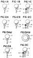
- One of the characteristic curves of this type of nonlinear resilient member is shown in Fig. 15.
- Fig. 15 Shown in Fig. 15 are characteristic curves for four types of PORON (registered trade mark), which is a product of INOAC Corporation, and their characteristics are only a little different from one another.
- the horizontal axis represents deflection and the vertical axis represents load.
- the characteristic curves show that the curves have gentle and stable slopes within the range of practical use.
- Fig. 4B represents the relation between the straightness or flatness of the portion of the holder which regulates the position of the cylindrical bar, and the developer layer unevenness on the surface of the developing sleeve.
- Fig. 7, 8, 9, 10, 11, 12, and 13 are partial diagrammatic views of another examples of the embodiment shown in Fig. 5.
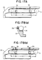
- Fig. 17 is a perspective view of the main portion of the example shown in Fig. 16.
- Fig. 13A shows an example outside the scope of the invention in which the head portion of the layer thickness regulator consists of two layers. It is covered with thin urethane rubber or silicon rubber layer. It is preferable that the core 'S' is covered by a rubber sheet 5′, the thickness of which is from 0.01mm to 1mm.
- Fig. 13B is an example outside the scope of the invention in which the bar consists of two layers.
- the outside of the cylindrical bar 5 is covered with a thin rubber layer 5′ made from urethane rubber or silicon rubber.
- Fine adjustment screws which are shown in examples Fig. 7B to 13B can be also installed in examples Fig. 7C to Fig. 13C in order to keep the developing sleeve 3 axis parallel with the cylindrical bar 5 or 5a axis. Thus, it becomes easier to accomplish the predetermined cylindricity and straightness of the cylindrical bar.
- the developing sleeve 3 is a cylinder made from nonmagnetic stainless steel rotating at the speed of 250rpm in the direction of the arrow mark on the drawing. Its diameter is 20 ⁇ mm and the roughness of its surface is '3S', as it was sand blasted.
- the stationary magnet roller 4 with eleven magnetic poles is installed inside the developing sleeve 3. The maximum magnetic flux density on the surface of the developing sleeve is kept at 600gauss.
- the third embodiment of the invention has almost the same structure as the example shown in Fig. 5B. But the direction of rotation of the developing sleeve is opposite to that of the photoreceptor. In other words, the circumferential surface of the developing sleeve moves in the same direction as that of the photoreceptor at the position where the developing sleeve faces the photoreceptor.
- the developer amount regulating member 5 is installed at the position as shown in Fig. 14A.
- the developing sleeve 3 is made of nonmagnetic stainless steel. Its diameter is 30 ⁇ mm, and its surface roughness is '1S'.
- the magnetic flux density of the magnetic roller is 700gauss at the surface of the sleeve.
- the number of the poles is eight.
- the cylindrical bar is made of stainless steel, the diameter of which is 7 ⁇ mm. The cylindrical bar is installed close to a pole of the magnetic roller 4 and it is held between the nonmagnetic flat spring 6 to press the bar and the developer amount regulating roller
- the pressure of the cylindrical bar onto the developing sleeve is the addition of the magnetic attraction, the weight of the bar, and the pressure by the flat spring 6.
- the regulating member 5 is magnetized by the magnetic field created by the stationary magnetic roller 4 in the developing sleeve, and attracted by the magnetic roller.
- the pressure is created by magnetic attraction by this method.
- the magnetic attraction by the cylindrical bar 5 is longitudinally uniform, and presses the developing sleeve 3 uniformly. As a result, an excellent developer layer can be obtained.
- the developing apparatus of the invention has excellent efficiency.
- the outstanding points are that the possibility of blocking caused by foreign objects is low, the efficiency of breaking the aggregated toner in pieces is high and white streaks hardly appear on the image.
- the variation of the pressure by the developer layer thickness regulating member has very little influence on the variation of the developer amount conveyed.
- the developing area is so small that there is no bad effect on the images by unnecessary electrification caused by friction.
- the variation of the developer amount is very little after the pressure at the pressing position on the developing sleeve by the developer amount regulating member has been once regulated. Therefore, the apparatus has excellent developing efficiency. Sticking of the two-component developer to the developer amount regulating member can be specially prevented in the apparatus. As a result, a uniformly thin developer layer is stably formed and high quality images without unevenness of density and deterioration of density can be obtained.
- a developer layer of stable thickness can be obtained without being affected by the variation of the developing sleeve rotating speed or the pressing position, especialy without being affected by the variation of the pressure of the developer amount regulator. Accordingly, a uniform and stable developer layer can be obtained by the developing apparatus of the invention with a light load compared with the conventional developing apparatus.
- the apparatus of the invention scarcely causes blinding by foreign object, is excellent at breaking aggregated toner to pieces, and white stripes hardly appear with this apparatus.
Landscapes
- Physics & Mathematics (AREA)
- General Physics & Mathematics (AREA)
- Magnetic Brush Developing In Electrophotography (AREA)
- Dry Development In Electrophotography (AREA)
Claims (10)
- Entwicklungsgerät zur Zufuhr eines Entwicklers zu einem Bildhaltemittel (1) zur Entwicklung eines elektrostatischen latenten Bildes auf dem Bildhaltemittel, wobei das Gerät folgendes umfaßt:
ein Entwicklertransportmittel (3) zum Transport des Entwicklers zu einer Entwicklungszone;
ein Entwicklerschichtdickenreguliermittel (5) zum Regulieren der Dicke des zur Entwicklungszone zu transportierenden Entwicklers;
ein Stützmittel (15) zum Stützen des Reguliermittels (5) und zum Drücken des Reguliermittels zum Entwicklertransportmittel (3);
dadurch gekennzeichnet, daß:
das Reguliermittel (5) in Form eines Stabs vorliegt und einen starren Flächenteil mit einem Krümmungsradius zwischen 0,5 mm und 15 mm aufweist;
das Entwicklertransportmittel (3) eine starre Fläche zum Transport des Entwicklers zur Entwicklungszone aufweist;
der starre Flächenteil des Reguliermittels (5) und die starre Fläche des Entwicklertransportmittels (3) jeweils eine Starrheit von nicht weniger als 10⁴ kg/cm² aufweisen; und
das Stützmittel (15) das Reguliermittel (5) beweglich stützt und es mit einer vorbestimmten Preßkraft zum Entwicklertransportmittel (3) drückt, um den starren Flächenteil des Reguliermittels mehr oder weniger auf die starre Fläche des Entwicklertransportmittels zu drücken. - Gerät nach Anspruch 1, dadurch gekennzeichnet, daß das Stützmittel (35, 36) das Reguliermittel (5) an zwei entlang seiner Länge voneinander beabstandeten Bereichen (36) stützt und beweglich drückt.
- Gerät nach Anspruch 1 oder 2, dadurch gekennzeichnet, daß das Stützmittel (35, 36) das Reguliermittel mit einem Glied (36) mit nichtlinearen elastischen Eigenschaften stützt und beweglich drückt.
- Gerät nach einem der Ansprüche 1 bis 3, dadurch gekennzeichnet, daß das Stützmittel (15) ein Einstellmittel (6, 151) aufweist, womit die seitliche Position des Reguliermittels gegenüber dem Stützmittel eingestellt werden kann.
- Gerät nach einem der Ansprüche 1 bis 4, dadurch gekennzeichnet, daß das Stützmittel (15) eine Fläche mit einer Flachheit von nicht mehr als 0,2 mm aufweist, um das Reguliermittel (5) an einer Fläche mit einer Zylindrizität von nicht mehr als 0,1 mm zu stützen.
- Gerät nach einem der Ansprüche 1 bis 5, dadurch gekennzeichnet, daß es sich bei dem Reguliermittel (5) um einen zylindrischen Stab handelt.
- Gerät nach einem der Ansprüche 1 bis 6, dadurch gekennzeichnet, daß hinter der starren Fläche des Entwicklertransportmittels (3) ein Magnet angeordnet ist und der starre Flächenteil des Reguliermittels (5) aus magnetischem Material besteht.
- Gerät nach Anspruch 7, dadurch gekennzeichnet, daß das Reguliermittel (5) durch magnetische Kraft auf das Entwicklertransportmittel (3) gedrückt wird.
- Gerät nach einem der Ansprüche 1 bis 6, dadurch gekennzeichnet, daß das Entwicklertransportmittel (3) aus nichtmagnetischem Material besteht und zum Transport eines Zweikomponentenentwicklers, der einen magnetischen Träger und einen Toner umfaßt, ausgelegt ist.
- Gerät nach einem der Ansprüche 1 bis 6, dadurch gekennzeichnet, daß das Entwicklertransportmittel (3) zum Transport eines Einkomponentenentwicklers ausgelegt ist.
Applications Claiming Priority (8)
| Application Number | Priority Date | Filing Date | Title |
|---|---|---|---|
| JP112975/88 | 1988-05-09 | ||
| JP63112975A JP2992693B2 (ja) | 1988-05-09 | 1988-05-09 | 現像装置 |
| JP122264/88 | 1988-05-18 | ||
| JP12226488 | 1988-05-18 | ||
| JP167076/88 | 1988-07-04 | ||
| JP63167076A JP2733605B2 (ja) | 1988-05-18 | 1988-07-04 | 現像装置 |
| JP217417/88 | 1988-08-31 | ||
| JP63217417A JP2838523B2 (ja) | 1988-08-31 | 1988-08-31 | 現像装置 |
Publications (3)
| Publication Number | Publication Date |
|---|---|
| EP0341894A2 EP0341894A2 (de) | 1989-11-15 |
| EP0341894A3 EP0341894A3 (en) | 1990-11-28 |
| EP0341894B1 true EP0341894B1 (de) | 1995-07-19 |
Family
ID=27470048
Family Applications (1)
| Application Number | Title | Priority Date | Filing Date |
|---|---|---|---|
| EP89304461A Expired - Lifetime EP0341894B1 (de) | 1988-05-09 | 1989-05-03 | Bildaufzeichnungsgerät |
Country Status (3)
| Country | Link |
|---|---|
| US (1) | US5054419A (de) |
| EP (1) | EP0341894B1 (de) |
| DE (1) | DE68923484T2 (de) |
Families Citing this family (20)
| Publication number | Priority date | Publication date | Assignee | Title |
|---|---|---|---|---|
| US5430528A (en) * | 1989-07-03 | 1995-07-04 | Hitachi, Ltd. | Magnetic brush with bristle height equal to developing gap |
| JPH0432852A (ja) * | 1990-05-30 | 1992-02-04 | Mita Ind Co Ltd | 電子写真現像方法 |
| JPH05127537A (ja) * | 1991-11-08 | 1993-05-25 | Fujitsu Ltd | 現像装置 |
| US5245392A (en) * | 1992-10-02 | 1993-09-14 | Xerox Corporation | Donor roll for scavengeless development in a xerographic apparatus |
| US5517286A (en) * | 1993-01-28 | 1996-05-14 | Canon Kabushiki Kaisha | Developing apparatus |
| US5450176A (en) * | 1993-05-20 | 1995-09-12 | Mita Industrial Co., Ltd. | Developing device with rigid member toner limiting means |
| US5523533A (en) * | 1993-05-28 | 1996-06-04 | Canon Kabushiki Kaisha | Developing device which restricts carrier using developing agent regulating rotary member |
| US5360940A (en) * | 1993-07-14 | 1994-11-01 | Xerox Corporation | Scavengeless two component development with an electroded development roll |
| JP3133875B2 (ja) * | 1993-10-08 | 2001-02-13 | 京セラミタ株式会社 | 小径スリーブを用いる現像方法及びそれに用いる現像剤用トナー |
| USRE38026E1 (en) * | 1993-11-29 | 2003-03-11 | Canon Kabushiki Kaisha | Developing device having regulating rotary member for regulating toner amount |
| US5781836A (en) * | 1994-11-28 | 1998-07-14 | Canon Kabushiki Kaisha | Developing device having regualting rotary member for regulating toner amount |
| JPH0934245A (ja) * | 1995-07-19 | 1997-02-07 | Hewlett Packard Co <Hp> | 電子写真術用材料移動ローラ |
| JP3221292B2 (ja) * | 1995-08-23 | 2001-10-22 | 富士通株式会社 | 現像剤の層厚規制ブレードとその製造方法およびそれを用いた画像形成装置 |
| US7013104B2 (en) | 2004-03-12 | 2006-03-14 | Lexmark International, Inc. | Toner regulating system having toner regulating member with metallic coating on flexible substrate |
| US7236729B2 (en) | 2004-07-27 | 2007-06-26 | Lexmark International, Inc. | Electrophotographic toner regulating member with induced strain outside elastic response region |
| US20070237552A1 (en) * | 2006-04-06 | 2007-10-11 | Mcalpine Robert W | Doctor Blade and Developer Assembly with Precision Diameter Radius for Improved Doctoring Consistency |
| JP5540787B2 (ja) * | 2010-03-16 | 2014-07-02 | 富士ゼロックス株式会社 | 現像装置、画像形成装置 |
| JP2014186179A (ja) * | 2013-03-25 | 2014-10-02 | Oki Data Corp | 現像装置、画像形成ユニット、及び画像形成装置 |
| US10386743B2 (en) * | 2016-09-12 | 2019-08-20 | Canon Kabushiki Kaisha | Developing device that reduces the bending of a developer regulating member when the developer regulating member receives developer pressure or magnetic force |
| JP2019124735A (ja) * | 2018-01-12 | 2019-07-25 | 京セラドキュメントソリューションズ株式会社 | 現像装置、およびこれを備えた画像形成装置 |
Family Cites Families (16)
| Publication number | Priority date | Publication date | Assignee | Title |
|---|---|---|---|---|
| US4100884A (en) * | 1976-02-25 | 1978-07-18 | Ricoh Company, Ltd. | Rubber developer roller using single component toner |
| GB2081135B (en) * | 1977-09-10 | 1982-09-08 | Canon Kk | Developing apparatus for electrostatic image |
| JPS5451848A (en) * | 1977-09-30 | 1979-04-24 | Canon Inc | Developing device |
| JPS5550274A (en) * | 1978-10-05 | 1980-04-11 | Canon Inc | Electrostatic image developing device |
| JPS56109374A (en) * | 1980-02-01 | 1981-08-29 | Canon Inc | Developing device |
| US4406536A (en) * | 1981-02-04 | 1983-09-27 | Ricoh Company, Ltd. | Developing device |
| JPS5865465A (ja) * | 1981-10-14 | 1983-04-19 | Minolta Camera Co Ltd | 静電潜像現像装置 |
| JPS5919969A (ja) * | 1982-07-26 | 1984-02-01 | Canon Inc | 現像装置 |
| JPS59126567A (ja) * | 1983-01-10 | 1984-07-21 | Canon Inc | 現像装置 |
| JPS6046577A (ja) * | 1983-08-24 | 1985-03-13 | Fuji Xerox Co Ltd | 非磁性一成分現像装置 |
| US4780741A (en) * | 1985-02-19 | 1988-10-25 | Kyocera Corporation | Method and apparatus for forming toner layer |
| JPS6217774A (ja) * | 1985-07-16 | 1987-01-26 | Kyocera Corp | トナ−層厚形成装置 |
| JPH0652449B2 (ja) * | 1985-09-30 | 1994-07-06 | 京セラ株式会社 | トナ−層厚形成装置 |
| US4908291A (en) * | 1986-02-18 | 1990-03-13 | Konishiroku Photo Industry Co., Ltd. | Method of regulating the thickness of a developer layer containing magnetic carrier and toner particles |
| JPS62231276A (ja) * | 1986-03-31 | 1987-10-09 | Konika Corp | 現像装置 |
| US4814818A (en) * | 1986-10-09 | 1989-03-21 | Konishiroku Photo Industry Co., Ltd. | Developer layer forming apparatus |
-
1989
- 1989-05-03 EP EP89304461A patent/EP0341894B1/de not_active Expired - Lifetime
- 1989-05-03 DE DE68923484T patent/DE68923484T2/de not_active Expired - Fee Related
-
1990
- 1990-10-25 US US07/604,321 patent/US5054419A/en not_active Expired - Fee Related
Also Published As
| Publication number | Publication date |
|---|---|
| DE68923484D1 (de) | 1995-08-24 |
| EP0341894A2 (de) | 1989-11-15 |
| EP0341894A3 (en) | 1990-11-28 |
| US5054419A (en) | 1991-10-08 |
| DE68923484T2 (de) | 1996-02-15 |
Similar Documents
| Publication | Publication Date | Title |
|---|---|---|
| EP0341894B1 (de) | Bildaufzeichnungsgerät | |
| EP1617297B1 (de) | Verfahren und Vorrichtung zur Bildentwicklung mit wirksamer Bildung einer gleichmäßigen Entwicklungsmittelschicht | |
| JP3073567B2 (ja) | 現像装置 | |
| EP0411891B1 (de) | Entwicklungsvorrichtung, nutzbar auf elektrophotographischem Gebiet | |
| US6148167A (en) | Developing apparatus with a developing regulating member | |
| US5325637A (en) | Developing apparatus with an improved sleeve | |
| EP0636950B1 (de) | Entwicklungsgerät mit einer sich drehenden Entwicklerzufuhreinheit einer Entwicklerträgereinheit | |
| JPH0511584A (ja) | 一成分系乾式現像装置のトナー薄層ブレード | |
| US6788913B1 (en) | Image forming apparatus method and developing device to obtain a stable image density | |
| JP2838523B2 (ja) | 現像装置 | |
| JPH05127511A (ja) | 現像装置 | |
| JP2847514B2 (ja) | 現像装置 | |
| JP2733605B2 (ja) | 現像装置 | |
| JP2791777B2 (ja) | 現像装置 | |
| JPH04355777A (ja) | 乾式現像装置のトナー薄層化ブレード | |
| JP2858119B2 (ja) | 現像装置 | |
| JP3905209B2 (ja) | 現像装置 | |
| JPH07181786A (ja) | 現像装置 | |
| JP2912793B2 (ja) | 現像装置並びに現像方法並びに画像形成装置 | |
| JP2937703B2 (ja) | 現像装置およびこの現像装置を備える画像形成装置 | |
| JPH0264674A (ja) | 現像装置 | |
| JP2727095B2 (ja) | 現像装置 | |
| JPH0619322A (ja) | 現像装置 | |
| JPH01282578A (ja) | 現像装置 | |
| JPH0736278A (ja) | 現像装置 |
Legal Events
| Date | Code | Title | Description |
|---|---|---|---|
| PUAI | Public reference made under article 153(3) epc to a published international application that has entered the european phase |
Free format text: ORIGINAL CODE: 0009012 |
|
| AK | Designated contracting states |
Kind code of ref document: A2 Designated state(s): DE FR GB IT |
|
| PUAL | Search report despatched |
Free format text: ORIGINAL CODE: 0009013 |
|
| AK | Designated contracting states |
Kind code of ref document: A3 Designated state(s): DE FR GB IT |
|
| 17P | Request for examination filed |
Effective date: 19901205 |
|
| 17Q | First examination report despatched |
Effective date: 19920609 |
|
| GRAA | (expected) grant |
Free format text: ORIGINAL CODE: 0009210 |
|
| AK | Designated contracting states |
Kind code of ref document: B1 Designated state(s): DE FR GB IT |
|
| PG25 | Lapsed in a contracting state [announced via postgrant information from national office to epo] |
Ref country code: IT Free format text: LAPSE BECAUSE OF FAILURE TO SUBMIT A TRANSLATION OF THE DESCRIPTION OR TO PAY THE FEE WITHIN THE PRE;WARNING: LAPSES OF ITALIAN PATENTS WITH EFFECTIVE DATE BEFORE 2007 MAY HAVE OCCURRED AT ANY TIME BEFORE 2007. THE CORRECT EFFECTIVE DATE MAY BE DIFFERENT FROM THE ONE RECORDED.SCRIBED TIME-LIMIT Effective date: 19950719 Ref country code: FR Effective date: 19950719 |
|
| REF | Corresponds to: |
Ref document number: 68923484 Country of ref document: DE Date of ref document: 19950824 |
|
| EN | Fr: translation not filed | ||
| PLBE | No opposition filed within time limit |
Free format text: ORIGINAL CODE: 0009261 |
|
| STAA | Information on the status of an ep patent application or granted ep patent |
Free format text: STATUS: NO OPPOSITION FILED WITHIN TIME LIMIT |
|
| 26N | No opposition filed | ||
| PGFP | Annual fee paid to national office [announced via postgrant information from national office to epo] |
Ref country code: GB Payment date: 19980424 Year of fee payment: 10 |
|
| PGFP | Annual fee paid to national office [announced via postgrant information from national office to epo] |
Ref country code: DE Payment date: 19980511 Year of fee payment: 10 |
|
| PG25 | Lapsed in a contracting state [announced via postgrant information from national office to epo] |
Ref country code: GB Free format text: LAPSE BECAUSE OF NON-PAYMENT OF DUE FEES Effective date: 19990503 |
|
| GBPC | Gb: european patent ceased through non-payment of renewal fee |
Effective date: 19990503 |
|
| PG25 | Lapsed in a contracting state [announced via postgrant information from national office to epo] |
Ref country code: DE Free format text: LAPSE BECAUSE OF NON-PAYMENT OF DUE FEES Effective date: 20000301 |