EP0341790A2 - Méthode et appareil pour la reproduction de bande magnétique en utilisant des têtes de tambour rotatif - Google Patents
Méthode et appareil pour la reproduction de bande magnétique en utilisant des têtes de tambour rotatif Download PDFInfo
- Publication number
- EP0341790A2 EP0341790A2 EP89201161A EP89201161A EP0341790A2 EP 0341790 A2 EP0341790 A2 EP 0341790A2 EP 89201161 A EP89201161 A EP 89201161A EP 89201161 A EP89201161 A EP 89201161A EP 0341790 A2 EP0341790 A2 EP 0341790A2
- Authority
- EP
- European Patent Office
- Prior art keywords
- data
- track
- magnetic tape
- magnetic
- reproducing
- Prior art date
- Legal status (The legal status is an assumption and is not a legal conclusion. Google has not performed a legal analysis and makes no representation as to the accuracy of the status listed.)
- Granted
Links
Images


Classifications
-
- H—ELECTRICITY
- H04—ELECTRIC COMMUNICATION TECHNIQUE
- H04N—PICTORIAL COMMUNICATION, e.g. TELEVISION
- H04N5/00—Details of television systems
- H04N5/76—Television signal recording
- H04N5/91—Television signal processing therefor
- H04N5/92—Transformation of the television signal for recording, e.g. modulation, frequency changing; Inverse transformation for playback
- H04N5/926—Transformation of the television signal for recording, e.g. modulation, frequency changing; Inverse transformation for playback by pulse code modulation
-
- G—PHYSICS
- G11—INFORMATION STORAGE
- G11B—INFORMATION STORAGE BASED ON RELATIVE MOVEMENT BETWEEN RECORD CARRIER AND TRANSDUCER
- G11B15/00—Driving, starting or stopping record carriers of filamentary or web form; Driving both such record carriers and heads; Guiding such record carriers or containers therefor; Control thereof; Control of operating function
- G11B15/02—Control of operating function, e.g. switching from recording to reproducing
- G11B15/12—Masking of heads; circuits for Selecting or switching of heads between operative and inoperative functions or between different operative functions or for selection between operative heads; Masking of beams, e.g. of light beams
- G11B15/14—Masking or switching periodically, e.g. of rotating heads
-
- G—PHYSICS
- G11—INFORMATION STORAGE
- G11B—INFORMATION STORAGE BASED ON RELATIVE MOVEMENT BETWEEN RECORD CARRIER AND TRANSDUCER
- G11B5/00—Recording by magnetisation or demagnetisation of a record carrier; Reproducing by magnetic means; Record carriers therefor
- G11B5/008—Recording on, or reproducing or erasing from, magnetic tapes, sheets, e.g. cards, or wires
- G11B5/00813—Recording on, or reproducing or erasing from, magnetic tapes, sheets, e.g. cards, or wires magnetic tapes
- G11B5/00847—Recording on, or reproducing or erasing from, magnetic tapes, sheets, e.g. cards, or wires magnetic tapes on transverse tracks
- G11B5/0086—Recording on, or reproducing or erasing from, magnetic tapes, sheets, e.g. cards, or wires magnetic tapes on transverse tracks using cyclically driven heads providing segmented tracks
-
- H—ELECTRICITY
- H04—ELECTRIC COMMUNICATION TECHNIQUE
- H04N—PICTORIAL COMMUNICATION, e.g. TELEVISION
- H04N5/00—Details of television systems
- H04N5/76—Television signal recording
- H04N5/91—Television signal processing therefor
- H04N5/93—Regeneration of the television signal or of selected parts thereof
- H04N5/937—Regeneration of the television signal or of selected parts thereof by assembling picture element blocks in an intermediate store
Definitions
- the present invention relates to a method and apparatus for reproducing a magnetic tape using rotary drum heads preferably applied in, for example, digital audio tape recorder of rotary head type (R-DAT).
- R-DAT digital audio tape recorder of rotary head type
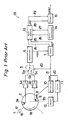
- FIG. 1 shows a magnetic tape player 19 in a digital audio tape recorder of rotary head type of a typical prior art.
- the magnetic tape player 19 is composed of a rotary drum 2 mounting magnetic heads 3a, 3b having two different azimuth angles, a detecting circuit 10 for leading out a track identification signal HSW in synchronism with the rotation of the rotary drum 2, an equalizer circuit 6, an input circuit 7, a main memory 13, and an output circuit 15.
- the magnetic heads 3a, 3b mounted on the axis of the diameter, on the side wall of the cylindrical rotary drum 2 scan a magnetic tape 1 obliquely, and read out the information written on the magnetic tape 1.
- the track identification signal HSW output from the detecting circuit 10 described below is given to a servo circuit 11 by way of a line l2.
- This servo circuit 11 controls the rotation of the motor 12 on the basis of the track identification signal HSW, and consequently the rotary drum 12 is rotated in the direction indicated by arrow 18.
- a detecting element 8 such as a Hall element detects the passing of a magnet 9 built in the rotary drum 2, and leads out a signal synchronized with the rotation of the rotary drum 2 to the detecting circuit 10. From the detecting circuit 10, for example, a track identification signal HSW is output, which becomes high level including the period of contact of the magnetic head 3a with the magnetic tape 1, and low level including the period of contact of the magnetic head 3b with the magnetic tape 1.
- the signals from the magnetic heads 3a, 3b are amplified by amplifiers 4a, 4b respectively, and are led out into terminals Sa, Sb of a changeover switch 5.
- the changeover switch 5 selectively causes either one of the terminals Sa, Sb to conduct to terminal Sc on the basis of the track identification signal HSW given to the lines l1, l3 from the detecting circuit 10.
- the terminal Sc is connected to the equalizer circuit 6.
- the frequency characteristic of the reproduced signal is adjusted, and the output from the equalizer circuit 6 is given to the input circuit 7.
- the input circuit 7 stores the data signal from the equalizer circuit 6 into the main memory 13 through line l4. At this time, in the input circuit 7, an address signal AD1 is supplied to the main memory 13 through line 15 so as to specify the address for storing the data signal. With respect to the data stored in the main memory 13, an error correction circuit 14 specifies an address through line 16. The data of the specified address is read out into the error correction circuit 14 by way of line 17, and a specified error correction process is carried out. The corrected data is sent out from the error correction circuit 14 to the main memory 13 by way of line l7. The corrected data is written into the address specified through line 16. In this way, the data having an error is rewritten into corrected data.
- the data of the address specified by an address signal AD2 supplied from the output circuit 15 through line 18 is read out into the output circuit 15 through line l9 sequentially from the main memory 13.
- the data being read out is output from the output circuit 15 sequentially as data signal DAOUT.
- the R-DAT when converting an audio signal into a digital signal to record in the magnetic tape 1, changes the sequence of the sampled digital signals, and records in the magnetic tape 1. Such recording method is called interleaving.
- the magnetic tape 1 When recording into the magnetic tape 1, the magnetic tape 1 runs in the direction indicated by arrow 17. When the data L0, L1, L2, ..., and data R0, R1, R2, ... at the time of sampling of left audio signal and right audio signal are fed in this sequence, such data are recorded in the magnetic tape 1 in the sequence changed as shown in FIG. 2. In the middle of the magnetic tape 1, a parity check code P which is an error correction code is rocorded together.
- the magnetic head 3a when the magnetic head 3a reads out the data from track A1, as shown in FIG. 3 (1), the magnetic head 3a reads out the data sequentially in the running direction of the head in the high level period W2 of the track identification signal HSW.
- the magnetic head 3b When the magnetic head 3a finishes reading out the data in the track A1, the magnetic head 3b reads out the data written in the track B1 in the next period W3. In this way, the data for the portion of one frame is read out in period W1.
- the signal PBSG which is read out by the magnetic heads 3a, 3b and output from the equalizer circuit 6 is shown in FIG. 3 (2).
- the signal PBSG from the equalizer circuit 6 is supplied and stored in the main memory 13 together with the address signal AD1 shown in FIG. 3 (3) in the input circuit 7.
- the data are stored in addresses N to N+ l, M to M+ l, different from the addresses in which data Li, Ri are stored.
- the data corrected by the error correction circuit 14 is read out by the output circuit 15.
- the address signal AD2 output from the output circuit 15 is shown in FIG. 3 (5).
- the data changed in the sequence by the interleaving as mentioned above is put back in the initial sequence when the address on the main memory 13 is specified by the address data AD2. In this way, the data signal DAOUT is output in the correct sequence from the output circuit 15 as shown in FIG. 3 (4).
- the magnetic tape player 19 the operation of reproducing the magnetic tape 1 while running in the direction indicated by arrow 16, or so-called reproduction in reverse direction is explained below.
- the magnetic head 3a reads out the information, for example, from the track A2, and later in the period W6 when the track identification signal HSW is at low level, the magnetic head 3b reads out the data in the track B1.
- the data for the portion of two tracks is read out, but it is misunderstood as to form one frame by track A2 and track B1 which are different frame constituent elements.
- the track identification signal HSW is shown in FIG. 4 (1), and the data signal PBSG is given in FIG. 4 (2).
- the data stored in the specified address in the main memory 13 by the address AD1 shown in FIG. 4 (3) is sequentially read out by the address signal AD2 through line l8 from the output circuit 15.
- the address sequence specified at this time is same as that in reproduction in normal direction mentioned above.
- the address signal AD2 is shown in FIG. 4 (5), and the data signal DAOUT output from the output circuit 15 is shown in FIG. 4 (4).
- this invention presents a method for reproducing a magnetic tape using rotary drum heads characterized by: reading a magnetic tape by using a rotary drum on which one each or more of magnetic heads having two different azimuth angles are mounted at spacing in the circumferential direction, forming a frame on this magnetic tape by a pair of one track formed by a magnetic head with a specific azimuth angle, and other track formed by other magnetic head with a different azimuth angle, - reading one track by the magnetic head having a specific azimuth angle, and the other track by the other magnetic head having a different azimuth angle, generating a track identification signal, when reproducing in the normal direction, which is either one of the high level or low level during reproduction period of one track and is the other one of the high level or low level during reproducction period of the other track, and leading out the contents recorded in one track and other track composing one frame by rearranging in the predetermined sequence in response to the track identification signal, and inverting the track identification signal, when reproducing in the reverse direction,
- the magnetic tape is read by using a rotary drum on which one each or more of magnetic heads having two different azimuth angles are mounted at a spacing in the circumferential direction.
- a frame is composed of a pair of a track formed by a magnetic head having a specific azimuth angle, and other track formed by the other magnetic head having a different azimuth angle, and one track is read by the magnetic head having a specific azumuth angle, and the other track is read by the magnetic head having the other azimuth angle.
- a track identification signal is generated, which is either one of the high level or low level during reproduction of one track, and the other one of the high level or low level during reproduction of the other track, and in response to this track identification signal, the contents recorded in the two tracks forming one frame are rearranged in the predetermined sequence, and led out.
- this track identification signal When reproducing in the reverse direction, this track identification signal is inverted, and in response to this inverted signal, the two tracks composing one frame are selected, and the contents recorded in the selected two tracks are rearranged in the reverse sequence of the reproduction in the normal direction, and led out.
- the data recorded in the magnetic tape can be output in the sequence completely opposite to the recording sequence when reproducing in the reverse direction. It is therefore possible to realize a magnetic tape reproducing apparatus using rotary drum heads possessing higher functions.
- the invention further presents an apparatus for reproducing a magnetic tape using rotary drum heads comprising: a rotary drum rotated in a predetermined direction, and having one each or more of magnetic heads possessing two different azimuth angles installed thereon in the peripheral direction, a magnetic tape sliding in contact with the rotary drum, and means for driving the magnetic tape running for driving the magnetic tape in a first running direction and in a second running direction opposite to the first running direction, wherein the magnetic tape has a frame composed of a pair of a track formed by a magnetic head having a specific azimuth angle, and other track formed by a magnetic head having a different azimuth angle, and one track is read by the magnetic head having a specific azimuth angle and the other track is read by the other magnetic head having a different specific azimuth angle, which further comprises: means for detecting the reading state for leading out the signal to express the reading state of the magnetic heads having two different azimuth angles, a memory for storing the data in two tracks forming one frame in the sequence of reading according to the output from the
- the magnetic tape reproducing apparatus using rotary drum heads of the invention also comprises means for correcting errors in every frame of data that has been read.
- the reading state detecting means of the magnetic tape reproducing apparatus using rotary drum heads of the invention further comprises a magnetic object of detection mounted on the rotary drum, and means for detecting the magnetic object magnetically being provided at a fixed position.
- the magnetic tape reproducing apparatus using rotary drum heads of the invention possesses a changeover switch for changing over and leading out the outputs of the magnetic heads in the period of each magnetic head contacting with the magnetic tape in response to the output of the reading state detecting means so as to supply the output of the changeover switch to the memory.
- FIG. 5 is a block diagram showing the structure of a magnetic tape player 43 in an embodiment of the invention.
- the magnetic tape player 43 is composed of a rotary drum 22, a detecting circuit 30 for generating a track identification signal HSW which is described later, an inverting circuit 36, an input circuit 27, a main memory 33, an output circuit 35, and a buffer circuit 37.
- Magnetic heads 23a, 23b are mounted on the cylindrical rotary drum 22 at positions 180 degrees opposite to each other.
- the magnetic heads 23a, 23b are installed at different azimuth angles in order to prevent noise due to crosstalk.
- the magnetic head 23a is mounted on the rotary drum 22 at an azimuth angle of +20 degrees, and the magnetic head 23b, -20 degrees.
- the rotary drum 22 is rotated in the direction indicated by arrow 51 about the axial line at a speed of, for example, 2000 rpm by means of a motor 32 mentioned later.
- the rotary drum 22 is also furnished with a magnet 29 for detecting the rotation of the rotary drum 22.
- a detecting element 28 realized by a Hall element or the like is fixed, and the rotation of the rotary drum 22 is detected by this.
- the detecting circuit 30 outputs a track identification signal HSW which becomes high level including the reproducing action period of the magnetic head 23a on the basis of the signal from the detecting element 28, and becomes low level including the reproduction period of the magnetic head 23b.
- This track identification signal HSW is given to the changeover switch 25, inverting circuit 36, and servo circuit 31.
- the servo circuit 31 controls the rotating speed of the motor 32 on the basis of the track identification signal HSW.
- the motor 32 rotates the rotary drum 22 in the direction indicated by arrow 51.
- FIG. 2 shows a track pattern on the magnetic tape 21.
- Tracks A0, A1, A2, ... are the portions recorded by the magnetic head 23a, and these tracks A0, A1, A2, ... are read by the magnetic head 23a.
- Tracks B0, B1, B2, ... are the portions recorded by the magnetic head 23b, and these tracks B0, B1, B2, ... are read by the magnetic head 23b.
- the data row is rearranged when recorded in the magnetic tape 21.
- the left signal of the audio signal is sequentially sampled and led out in the sequence of data L0, L1, L2, ... (collectively called data Li), while the right signal is sampled and sequentially led out in the sequence of R0, R1, R2, ... (collectively called data Ri).
- data Li the data Li
- R0, R1, R2, ... the data Ri
- the data Li, Ri are rearranged in their sequence, and are recorded in the magnetic tape 21.
- a parity check code P is recorded as a correction code for correcting an error.
- a set of data is composed of plural bits, and has a specific meaning. This rearrangement is completed within one frame Fi.
- the magnetic tape 21 is run and driven by means for driving magnetic tape running 48.
- the signals read out by the magnetic heads 23a, 23b from the magnetic tape 21 are amplified by amplifiers 24a, 24b, and are led out into terminals Ta,Tb of the changeover switch 25.
- the changeover circuit 25 sets the terminals Ta, Tc in conductive state when the track identification signal HSW is at high level, and sets the terminals Tb, Tc in conductive state when the track identification signal HSW is at low level. As a result, the reproduction signals from the magnetic heads 23a, 23b are changed over, and are led out into the equalizer circuit 26.
- a signal PBSG is supplied to the input circuit 27 through line M3.
- the input circuit 27 outputs the data from the equalizer circuit 26, together with the address signal, to the main memory 33, on the basis of the signal HSW1 from the inverting circuit 36 which is described later.
- an identification signal generating circuit 42 When either reproduction in the normal direction or reproduction in the reverse direction is specified by means for setting 47, an identification signal generating circuit 42 outputs an identification signal RS which is at low level when reproducing in the normal direction, and high level when reproducing in the reverse direction.
- the inverting circuit 36 on the basis of this identification signal RS, leads out the track identification signal HSW to the input circuit 27 as signal HSW1 when reproducing in the normal direction, and leads out the inverted signal of the track identification signal HSW to the input circuit 27 as signal HSW1 when reproducing in the reverse direction.
- the magnetic tape running driving means 48 runs and drives the magnetic tape 21 in the direction of arrow 52 when reproducing in the normal direction while the identification signal RS is at low level, and runs and drives and magnetic tapes 21 in the direction of arrow 53 when reproducing in the reverse direction while the identification signal RS is at high level.
- the input circuit 27 specifies the address on the main memory 33 by the address signal AD1 supplied through the address bus M5, and stored the data from the equalizer circuit 26 in the unit of one frame, at the specified address of the main memory 33 through the data bus M4.
- the data of one frame stored in the main memory 33 is corrected, when an error is contained, by the parity check code P described below in an error correction circuit 34.
- the error correction circuit 34 specifies the address on the main memory 33 through address bus M6, and reads out the data at the specified address through data bus M7, and corrects the error.
- the corrected data is written into the main memory 33 from the data bus M7, at the specified address through the address bus M6.
- the data on the main memory 33 after error correction is read out by the output circuit 35.
- the output circuit 35 specifies the address on the main memory 33 through the address bus M8, and reads out the data of the specified address through the data bus M9.
- the operation for specifying the address of the output circuit 35 is conducted as mentioned below. Consequently, the data Li, Ri changed in the sequence when recording into the magnetic tape 21 is returned to the original sequence and output.
- a clock signal CLK is led out to the buffer circuit 37 by way of line M11.
- the data signal DAOUT read out from the main memory 33 through the line M10 is led out to the buffer circuit 37 together with the clock signal CLK.
- the buffer circuit 37 comprises memory 39, input circuit 38, and output circuit 40.
- the clock signal CLK and data signal DAOUT from the output circuit 35 are supplied to the input circuit 38.
- the input circuit 38 outputs the data through data bus M12, and also outputs address signal AD3 through address bus M13, thereby specifying the address on the memory 39. Such operation is effected on the data of every one frame.
- the input signal 38 receives the identification signal RS mentioned above, and when reproducing in the reverse direction, the lower one bit is inverted in the address signal when specifying the address as mentioned below, and the data is supplied to the memory 39 through address bus M13.
- the data for one frame stored in the memory 39 is read out by the output circuit 40.
- the output circuit 40 specifies the address by the address signal increasing sequentially from 0 by the address signal AD4 through the address bus M14 when reproducing in the normal direction as mentioned below, and reads out the data of the specified address through the data bus M15, and outputs as the data signal BUFOUT.
- the address is specified by the sequentially decreasing address number. Therefore, when reproducing in the reverse direction, the data is read out in the completely reverse sequence as in reproduction in the normal direction from the memory 39. Reading of data from the memory 39 by the output circuit 40 is synchronized with the clock signal from the output clock signal generating circuit 41.
- FIG. 6 is a diagram showing a circuit structure example of the inverting circuit 36.
- the inverting circuit 36 comprises, for example, an exclusive OR gate 36a.
- the track identification signal HSW from the detecting circuit 30 is supplied, and at the other input unit, the identification signal RS from the identification signal generating circuit 42 is given.
- the output from the exclusive OR gate 36a is given to the input circuit 27 as signal HSW1.
- the truth value table of such exclusive OR gate 36a is shown in Table 1.
- FIG. 7 is a diagram showing the structure relating to the address specification of the input circuit 38.
- the input circuit 38 comprises, for example, a counter 44 and an exclusive OR gate 45.
- a clock signal CLK from the output circuit 35 is fed, and the pulse of the clock signal CLK is latched, and the count value is increased sequentially.
- This count value is output from terminals A0 to Am.
- the terminal A0 of the lowest bit is connected to one input unit of the exclusive OR gate 45, and the other input unit of this exclusive OR gate 45 is provided with identification signal RS from the identification signal generating circuit 42.
- the output from the exclusive OR gate 45 and the output wires from terminals A1 to Am compose the address bus M13.
- FIG. 8 is a diagram showing a constitution relating to address specification of output circuit 40.
- the output circuit 40 includes an up-down counter 46, and this up-down counter 46 is provided with clock signal CK from the output clock signal generating circuit 41, and an identification signal RS from the identification signal generating circuit 42.
- the up-down counter 46 sequentially increases the count value by latching the pulses of clock signal CK when the identification signal RS is at low level, and decreases the count value sequentially when the identification signal Rs is at high level. This count value is led out to terminals B0 to Bm.
- the output wires from the terminals B0 to Bm compose an address bus M14 and are connected to the memory 39.
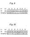
- FIG. 9 is a timing chart for explaining the operation in reproduction in the normal direction in the up-down counter 46.
- the up-down counter 46 When data for one frame is stored in the memory 39, the up-down counter 46 outputs an address signal AD4 in synchronism with the clock signal CK from the output clock signal generating circuit 41 shown in FIG. 9 (1).
- the address signal AD4 is sequentially increased from 0 as shown in FIG. 9 (2).
- the data signal BUFOUT output from the output circuit 40 as being read out from the memory 39 at this time is shown in FIG. 9 (3).
- FIG. 10 is a timing chart for explaining the operation in reproduction in the reverse direction of the output circuit 40.
- the identification signal RS is at high level, and the up-down counter 46 functions as a down counter.
- a count value for sequentially decreasing from the initial value 2n+1 is output from the up-down counter 46 as address signal AD4.
- the data signal BUFOUT supplied from the output circuit 40 becomes a signal expressing a data row in a completely different sequence from the reproduction in the normal direction.
- FIG. 11 is a timing chart for explaining the operation in reproduction in the normal direction of the magnetic tape player 43.
- the track identification signal HSW is at high level in period T2 as shown in FIG. 11 (1), and is at low level in period T3.
- Period Tl is the rotation period of the rotary drum 22.
- the data signal PBSG shown in FIG. 11 (2) is output. In period T1, this data signal PBSG is composed of the data read out from the track A1 by the magnetic head 23a in period T2 and the data read out from the track B1 by the magnetic head 23b in period T3.
- the input circuit 27 recognizes the data signal PBSG entered in the period when the signal HSW1 is at high level by this signal HSW1 of the same waveform as the track identification signal HSW when reproducing in the normal direction, and in the subsequent low level period, as the signals of one frame, and outputs the address signal AD1 in synchronism with the entered data signal PBSG.
- the address signal AD1 is shown in FIG. 11(3).
- the output circuit 35 specifies the address on the main memory 33 in the form of address signal AD2 shown in FIG. 11 (5), and reads out the data stored at the specified address, and output as data signal DAOUT.
- the data signal DAOUT is as shown in FIG. 11 (4).
- the input circuit 38 attaches an address to the data row supplied from the output circuit 35.
- the form of specifying the address at this time is as shown in FIG. 11 (6). Consequently, data Li, Ri in the data signal DAOUT are stored in the memory 39 in the same sequence as the output from the output circuit 35.
- the address signal AD4 increases sequentially from 0, and the address on the memory 39 is specified accordingly.
- the data at the specified address is read out from the memory 39.
- the data signal BUFOUT output from the output circuit 40 is shown in FIG. 11 (7).
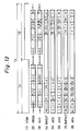
- FIG. 12 is a timing chart for explaining the operation in reproduction in the reverse direction of the magnetic tape player 43.
- the track identification signal HSW is at low level in period T5 as shown in FIG. 12 (1), and is at high level in period T6.
- the magnetic tape 21 is run in the direction indicated by arrow 53. Therefore, from the equalizer circuit 26, the data signal PBSG shown in FIG. 12 (2) is output.
- the scanning direction of the magnetic heads 23a, 23b on the magnetic tape 21 changes, but the rotating speed of the rotary drum 22 is sufficiently faster than the running speed of the magnetic tape, and the change in the running direction is slight, and the magnetic heads 23a, 23b can read the data in tracks Ai, Bi, respectively.
- this data signal PBSG is the signal read out of the track B1 by the magnetic head 23b in period T5, and the signal read out of the track B1 by the magnetic head 23a in period T6.
- the input circuit 27 when reproducing in the reverse direction, the signal HSW1 inverted from the track identification signal HSW is given as shown in Table l,by means of the inverting circuit 36. Accordingly, the input circuit 27 recognizes the data signal PBSG entered in the period when the signal HSW1 is at high level and in the subsequent low level period, as signals in one frame, and outputs an address signal AD1 in synchronism with the input data signal PBSG.
- the address signal AD1 is shown in FIG. 12 (3).
- the output circuit 35 specifies the address on the main memory 33 by the address signal AD2 supplied in the form shown in FIG. 12 (5), and reads out and outputs the data stored at the specified address.
- the data signal DAOUT is shown in FIG. 12 (4).
- the input circuit 38 attaches an address to the data row supplied from the output circuit 35. At this time, when specifying the address, the lowest bit of the counter 44 is inverted by the exclusive OR gate 45, and the form of address specification at this time is as shown in FIG. 12 (6). As a result, in the memory 39, the data signal DAOUT is stored in the sequence of exchanging Ri and Li.
- the address signal AD4 sequentially decreases from 2n+1, and the address on the memory 39 is specified accordingly.
- the data at the specified address is read out from the memory 39.
- the data signal BUFOUT output from the output circuit 40 is as shown in FIG. 12 (7), and the data Li, Ri are output in the completely different sequence of the order in reproduction in the normal direction.
- the data written in the magnetic tape 21 can be output in completely different sequence from the reproduction in the normal direction.
- the reproduction in the reverse direction can be realized.
- the magnetic tape player of R-DAT is explained, but the invention may be similarly applied to any other magnetic tape reproducing apparatus using rotary drum heads for reproducing the magnetic tape in which data is recorded in two adjacent tracks as one block, such as pulse coded modulation reproduction apparatus of video tape, and other magnetic tape players using rotary drum.
Applications Claiming Priority (2)
| Application Number | Priority Date | Filing Date | Title |
|---|---|---|---|
| JP63113288A JP2695186B2 (ja) | 1988-05-09 | 1988-05-09 | 回転ドラムヘッド磁気テープ再生装置 |
| JP113288/88 | 1988-05-09 |
Publications (3)
| Publication Number | Publication Date |
|---|---|
| EP0341790A2 true EP0341790A2 (fr) | 1989-11-15 |
| EP0341790A3 EP0341790A3 (fr) | 1991-02-27 |
| EP0341790B1 EP0341790B1 (fr) | 1993-10-27 |
Family
ID=14608381
Family Applications (1)
| Application Number | Title | Priority Date | Filing Date |
|---|---|---|---|
| EP89201161A Expired - Lifetime EP0341790B1 (fr) | 1988-05-09 | 1989-05-08 | Méthode et appareil pour la reproduction de bande magnétique en utilisant des têtes de tambour rotatif |
Country Status (4)
| Country | Link |
|---|---|
| US (1) | US5051848A (fr) |
| EP (1) | EP0341790B1 (fr) |
| JP (1) | JP2695186B2 (fr) |
| DE (1) | DE68910176T2 (fr) |
Cited By (3)
| Publication number | Priority date | Publication date | Assignee | Title |
|---|---|---|---|---|
| EP0341794A2 (fr) * | 1988-05-10 | 1989-11-15 | Sharp Kabushiki Kaisha | Méthode et appareil de reproduction de bande magnétique par utilisation de têtes de tambour rotatif |
| EP0500358A2 (fr) * | 1991-02-19 | 1992-08-26 | Matsushita Electric Industrial Co., Ltd. | Méthode de traitement de signaux d'un VTR digital |
| EP1118992A1 (fr) * | 1999-07-29 | 2001-07-25 | Matsushita Electric Industrial Co., Ltd. | Unite d'enregistrement/de reproduction magnetique |
Families Citing this family (6)
| Publication number | Priority date | Publication date | Assignee | Title |
|---|---|---|---|---|
| JPH0770152B2 (ja) * | 1989-09-04 | 1995-07-31 | シャープ株式会社 | 回転ヘッド形磁気テープ記録再生装置 |
| JPH03132183A (ja) * | 1989-10-18 | 1991-06-05 | Hitachi Ltd | ディジタル画像再生方式 |
| US5418774A (en) * | 1990-03-23 | 1995-05-23 | Matsushita Electric Industrial Co., Ltd. | Optical head system and its optical disc |
| US5844737A (en) * | 1990-11-14 | 1998-12-01 | Canon Kabushiki Kaisha | Reproducing apparatus with different reproduction data for normal and search modes which scans two areas of a split tape recording medium in opposite directions |
| US5481413A (en) * | 1992-10-27 | 1996-01-02 | Sony Corporation | Magnetic recording and reproducing apparatus for a helical-scan system adapted for reproduction of data in a reverse sequential order from recording of data |
| US6141487A (en) * | 1994-03-14 | 2000-10-31 | Matsushita Electric Industrial Co., Ltd. | Data recording/reproducing apparatus and method for high speed play |
Citations (4)
| Publication number | Priority date | Publication date | Assignee | Title |
|---|---|---|---|---|
| WO1982000558A1 (fr) * | 1980-07-28 | 1982-02-18 | Physics Inc Spin | Effet de ralenti obtenu en utilisant un enregistrement longitudinal et un transport de bande en avant/en arriere |
| GB2086691A (en) * | 1980-10-27 | 1982-05-12 | Sony Corp | Signal processing method for digital signals possibly containing errors |
| EP0080297A1 (fr) * | 1981-11-20 | 1983-06-01 | Sony Corporation | Arrangement d'enregistrement et de reproduction sur bande magnétique |
| EP0180432A2 (fr) * | 1984-11-02 | 1986-05-07 | Sony Corporation | Appareil pour la reproduction de signaux numériques |
Family Cites Families (3)
| Publication number | Priority date | Publication date | Assignee | Title |
|---|---|---|---|---|
| JPH0690826B2 (ja) * | 1985-04-05 | 1994-11-14 | ソニー株式会社 | 信号再生装置 |
| JP2633526B2 (ja) * | 1986-01-16 | 1997-07-23 | ソニー株式会社 | 記録再生装置 |
| JPS6349662U (fr) * | 1986-09-19 | 1988-04-04 |
-
1988
- 1988-05-09 JP JP63113288A patent/JP2695186B2/ja not_active Expired - Fee Related
-
1989
- 1989-05-08 EP EP89201161A patent/EP0341790B1/fr not_active Expired - Lifetime
- 1989-05-08 DE DE89201161T patent/DE68910176T2/de not_active Expired - Fee Related
- 1989-05-09 US US07/350,841 patent/US5051848A/en not_active Expired - Fee Related
Patent Citations (4)
| Publication number | Priority date | Publication date | Assignee | Title |
|---|---|---|---|---|
| WO1982000558A1 (fr) * | 1980-07-28 | 1982-02-18 | Physics Inc Spin | Effet de ralenti obtenu en utilisant un enregistrement longitudinal et un transport de bande en avant/en arriere |
| GB2086691A (en) * | 1980-10-27 | 1982-05-12 | Sony Corp | Signal processing method for digital signals possibly containing errors |
| EP0080297A1 (fr) * | 1981-11-20 | 1983-06-01 | Sony Corporation | Arrangement d'enregistrement et de reproduction sur bande magnétique |
| EP0180432A2 (fr) * | 1984-11-02 | 1986-05-07 | Sony Corporation | Appareil pour la reproduction de signaux numériques |
Cited By (7)
| Publication number | Priority date | Publication date | Assignee | Title |
|---|---|---|---|---|
| EP0341794A2 (fr) * | 1988-05-10 | 1989-11-15 | Sharp Kabushiki Kaisha | Méthode et appareil de reproduction de bande magnétique par utilisation de têtes de tambour rotatif |
| EP0341794B1 (fr) * | 1988-05-10 | 1994-07-20 | Sharp Kabushiki Kaisha | Méthode et appareil de reproduction de bande magnétique par utilisation de têtes de tambour rotatif |
| EP0500358A2 (fr) * | 1991-02-19 | 1992-08-26 | Matsushita Electric Industrial Co., Ltd. | Méthode de traitement de signaux d'un VTR digital |
| EP0500358A3 (en) * | 1991-02-19 | 1993-11-24 | Matsushita Electric Ind Co Ltd | Signal processing method of digital vtr |
| EP1118992A1 (fr) * | 1999-07-29 | 2001-07-25 | Matsushita Electric Industrial Co., Ltd. | Unite d'enregistrement/de reproduction magnetique |
| EP1118992A4 (fr) * | 1999-07-29 | 2003-05-02 | Matsushita Electric Ind Co Ltd | Unite d'enregistrement/de reproduction magnetique |
| US7076157B1 (en) | 1999-07-29 | 2006-07-11 | Matsushita Electric Industrial Co., Ltd. | Magnetic recording and reproducing apparatus |
Also Published As
| Publication number | Publication date |
|---|---|
| JPH01282707A (ja) | 1989-11-14 |
| DE68910176T2 (de) | 1994-05-05 |
| EP0341790A3 (fr) | 1991-02-27 |
| EP0341790B1 (fr) | 1993-10-27 |
| DE68910176D1 (de) | 1993-12-02 |
| JP2695186B2 (ja) | 1997-12-24 |
| US5051848A (en) | 1991-09-24 |
Similar Documents
| Publication | Publication Date | Title |
|---|---|---|
| EP0163736B1 (fr) | Dispositif de traitement de signaux de modulation par impulsion codee (mic) | |
| US5155636A (en) | Apparatus and method for recording and reproducing digital data | |
| US4774605A (en) | Rotary head type digital signal playback | |
| EP0341790B1 (fr) | Méthode et appareil pour la reproduction de bande magnétique en utilisant des têtes de tambour rotatif | |
| EP0278702B1 (fr) | Appareil pour la reproduction d'un signal numérique | |
| EP0336424B1 (fr) | Appareil de reproduction de signaux de données pour un enregistrement à balayage hélicoidal | |
| JP2513204B2 (ja) | Pcm信号再生装置の速度制御回路 | |
| US5483389A (en) | Reproducing apparatus for temporarily writing reproducing data into memory | |
| US5155641A (en) | Helical scan magnetic tape recording apparatus for reforming read-after-write storage of manufacturing rotary head used therein | |
| US5099375A (en) | Four read and write heads on a drum arranged to prevent overlapping of tracing periods | |
| US5121264A (en) | Method and apparatus for reproduction of magnetic tape by using rotary drum heads | |
| US4829387A (en) | Rotary head type digital signal reproducing device for controlling tape speed according to a tracking error | |
| JPS59195306A (ja) | Pcm信号の記録再生装置 | |
| EP0416563B1 (fr) | Appareil d'enregistrement et de reproduction à bande magnétique avec de tête rotative | |
| EP0500358A2 (fr) | Méthode de traitement de signaux d'un VTR digital | |
| JPH0697543B2 (ja) | Pcmデ−タの記録装置 | |
| US5844737A (en) | Reproducing apparatus with different reproduction data for normal and search modes which scans two areas of a split tape recording medium in opposite directions | |
| JP3231121B2 (ja) | ノントラッキング方式の再生装置 | |
| EP0706182A2 (fr) | Appareil d'enregistrement et de reproduction magnétique | |
| JPH0336887A (ja) | デイジタル画像再生方式 | |
| JPH0518298B2 (fr) | ||
| JPH076311A (ja) | 磁気記録再生装置 | |
| JP2000163708A (ja) | データ記録再生装置 | |
| JPH087939B2 (ja) | 時間軸補正装置 | |
| JPH07244934A (ja) | ディジタル信号の記録再生装置 |
Legal Events
| Date | Code | Title | Description |
|---|---|---|---|
| PUAI | Public reference made under article 153(3) epc to a published international application that has entered the european phase |
Free format text: ORIGINAL CODE: 0009012 |
|
| AK | Designated contracting states |
Kind code of ref document: A2 Designated state(s): DE GB |
|
| PUAL | Search report despatched |
Free format text: ORIGINAL CODE: 0009013 |
|
| 17P | Request for examination filed |
Effective date: 19901219 |
|
| AK | Designated contracting states |
Kind code of ref document: A3 Designated state(s): DE GB |
|
| 17Q | First examination report despatched |
Effective date: 19930120 |
|
| GRAA | (expected) grant |
Free format text: ORIGINAL CODE: 0009210 |
|
| AK | Designated contracting states |
Kind code of ref document: B1 Designated state(s): DE GB |
|
| REF | Corresponds to: |
Ref document number: 68910176 Country of ref document: DE Date of ref document: 19931202 |
|
| PLBE | No opposition filed within time limit |
Free format text: ORIGINAL CODE: 0009261 |
|
| STAA | Information on the status of an ep patent application or granted ep patent |
Free format text: STATUS: NO OPPOSITION FILED WITHIN TIME LIMIT |
|
| 26N | No opposition filed | ||
| PGFP | Annual fee paid to national office [announced via postgrant information from national office to epo] |
Ref country code: GB Payment date: 19980429 Year of fee payment: 10 |
|
| PGFP | Annual fee paid to national office [announced via postgrant information from national office to epo] |
Ref country code: DE Payment date: 19980515 Year of fee payment: 10 |
|
| PG25 | Lapsed in a contracting state [announced via postgrant information from national office to epo] |
Ref country code: GB Free format text: LAPSE BECAUSE OF NON-PAYMENT OF DUE FEES Effective date: 19990508 |
|
| GBPC | Gb: european patent ceased through non-payment of renewal fee |
Effective date: 19990508 |
|
| PG25 | Lapsed in a contracting state [announced via postgrant information from national office to epo] |
Ref country code: DE Free format text: LAPSE BECAUSE OF NON-PAYMENT OF DUE FEES Effective date: 20000301 |