EP0341464A2 - Senseur d'accélération ou de décélération - Google Patents
Senseur d'accélération ou de décélération Download PDFInfo
- Publication number
- EP0341464A2 EP0341464A2 EP89107177A EP89107177A EP0341464A2 EP 0341464 A2 EP0341464 A2 EP 0341464A2 EP 89107177 A EP89107177 A EP 89107177A EP 89107177 A EP89107177 A EP 89107177A EP 0341464 A2 EP0341464 A2 EP 0341464A2
- Authority
- EP
- European Patent Office
- Prior art keywords
- permanent magnets
- permanent magnet
- recess
- displaceable
- recesses
- Prior art date
- Legal status (The legal status is an assumption and is not a legal conclusion. Google has not performed a legal analysis and makes no representation as to the accuracy of the status listed.)
- Granted
Links
Images
Classifications
-
- G—PHYSICS
- G01—MEASURING; TESTING
- G01P—MEASURING LINEAR OR ANGULAR SPEED, ACCELERATION, DECELERATION, OR SHOCK; INDICATING PRESENCE, ABSENCE, OR DIRECTION, OF MOVEMENT
- G01P15/00—Measuring acceleration; Measuring deceleration; Measuring shock, i.e. sudden change of acceleration
-
- G—PHYSICS
- G01—MEASURING; TESTING
- G01P—MEASURING LINEAR OR ANGULAR SPEED, ACCELERATION, DECELERATION, OR SHOCK; INDICATING PRESENCE, ABSENCE, OR DIRECTION, OF MOVEMENT
- G01P15/00—Measuring acceleration; Measuring deceleration; Measuring shock, i.e. sudden change of acceleration
- G01P15/02—Measuring acceleration; Measuring deceleration; Measuring shock, i.e. sudden change of acceleration by making use of inertia forces using solid seismic masses
- G01P15/08—Measuring acceleration; Measuring deceleration; Measuring shock, i.e. sudden change of acceleration by making use of inertia forces using solid seismic masses with conversion into electric or magnetic values
- G01P15/135—Measuring acceleration; Measuring deceleration; Measuring shock, i.e. sudden change of acceleration by making use of inertia forces using solid seismic masses with conversion into electric or magnetic values by making use of contacts which are actuated by a movable inertial mass
-
- H—ELECTRICITY
- H01—ELECTRIC ELEMENTS
- H01H—ELECTRIC SWITCHES; RELAYS; SELECTORS; EMERGENCY PROTECTIVE DEVICES
- H01H35/00—Switches operated by change of a physical condition
- H01H35/14—Switches operated by change of acceleration, e.g. by shock or vibration, inertia switch
- H01H35/147—Switches operated by change of acceleration, e.g. by shock or vibration, inertia switch the switch being of the reed switch type
-
- H—ELECTRICITY
- H01—ELECTRIC ELEMENTS
- H01H—ELECTRIC SWITCHES; RELAYS; SELECTORS; EMERGENCY PROTECTIVE DEVICES
- H01H9/00—Details of switching devices, not covered by groups H01H1/00 - H01H7/00
- H01H2009/0083—Details of switching devices, not covered by groups H01H1/00 - H01H7/00 using redundant components, e.g. two pressure tubes for pressure switch
Definitions
- the invention relates to an acceleration or deceleration sensor with a housing which has a plurality of mutually parallel tunnel-shaped recesses, a reed switch being arranged in at least one recess and two rod-shaped permanent magnets being arranged one behind the other in the direction of their longitudinal axes in at least one other recess.
- the arrangement of the permanent magnets is such that two poles of the same name of the permanent magnets face each other, at least one of the permanent magnets being displaceable in the longitudinal direction.
- Such sensors are known, for example, from German Patent 33 38 287. They are used, among other things, in safety devices for motor vehicles.
- safety devices can consist, for example, of a bag inflatable with compressed air or another gas, which is arranged in the region of the steering wheel and which is suddenly inflated in the event of a rear-end collision, thereby preventing the driver from hitting the steering wheel.
- the compressed air required to inflate the sack is carried in a compressed air bottle, which is normally closed by means of a solenoid valve.
- the solenoid valve In the event of a rear-end collision, the solenoid valve is opened and the path for the compressed air is opened so that it can flow from the storage bottle into the sack mentioned.
- the solenoid valve can be actuated, ie opened, with the sensor proposed here.
- the Senso can, for example, directly switch a trigger system, for example a thyristor ignition or other trigger electronics.
- Sensors of the type described are required in large numbers. It is assumed that the sensors themselves take up as little space as possible and that their response behavior fluctuates only within narrow limits. In addition, it is expected that the response range, that is to say the acceleration or deceleration at which the reed switch is closed, can be set according to requirements, the set value naturally being kept as precisely as possible. The requirements are difficult to meet with conventional designs. One helps, for example, by manufacturing a larger number of sensors, measuring them and selecting them according to the measurement results.
- the invention has for its object to further develop the known acceleration or deceleration sensors so that a more precise and more economical production is possible, in which case the spread of the set response values should also be less.
- the known sensors are based on a housing which has a plurality of, for example two mutually parallel, tunnel-shaped recesses, one in a recess Reed switch and in the other recess two rod-shaped permanent magnets are housed in the manner described (DE-PS 33 38 287)
- the solution consists in the combination of the following features: -
- the recesses for receiving the reed switches are each equipped with a cover that can be removed transversely to the longitudinal axis of the recess;
- the recesses for receiving the displaceable permanent magnets are closed on their outer end with an adjusting screw.
- the reed switch Due to the cover, which normally closes the recess for receiving the reed switch or switches, the reed switch can easily be used from the outside when mounting the sensors.
- the position of the reed switch can be adjusted within narrow limits and the housing can be processed in automatic assembly machines due to its new design.
- the cover After inserting the reed switch, the cover is put on, whereby the reed switch is held firmly in its position.
- the adjustable permanent magnet can now also be used to bring the displaceable permanent magnet into its optimal starting position, as a result of which its relative position to the reed switch can be set precisely. This adjustment can be carried out by simply turning the screw mentioned from the front. If the movable magnet is brought into an optimal starting position, the adjusting screw is locked, which can be caused, for example, by hard wax, varnish, a resin or the like. can happen.
- the proposed acceleration or deceleration sensor can basically be constructed so that it only has a reed switch and a movable rod magnets in mutually parallel tunnel-shaped recesses. This normal construction is basically sufficient to carry out the required switching operation. In some cases, however, it is desirable to switch several mutually independent reed switches simultaneously, for reasons of redundancy. For the same reasons, it may be desirable to have several movable permanent magnets available. In these cases, the housing can be manufactured with double or even multiple assembly, the arrangement being such that several reed switches are influenced and switched by a single permanent magnet. To increase safety, it is also possible to accommodate several permanent magnets in different recesses, which act on the same reed switch or on the same group of reed switches
- the cover which is located above the recesses for the reed switch or switches, is designed as a hinged cover, which is connected to the housing via one or more film hinges.
- the entire housing including the hinged cover can be produced as a single injection molded part, which reduces both the costs and the tolerance limits for dimensional deviations.
- Tough and preferably impact-resistant organic polymers for example polyamides, in particular glass fiber-reinforced polyamides, are suitable as materials for the production of such housings.
- the recess for receiving the permanent magnets is divided into two successive subspaces by a constriction, in each of which one of the two permanent magnets is arranged.
- Such a constriction which can easily be drawn in during the manufacture of the housing by the injection molding process, ensures that the fixed permanent magnet, which acts as a brake magnet, can easily be placed in its intended position without deviations occurring in the position.
- the movable permanent magnet then comes into the remaining, usually larger, subspace in which it can move freely.
- the constriction is an intermediate wall.
- a damping liquid which means that an additional means is available to influence the movement behavior of this magnet and thus the switching behavior of the entire sensor.
- a gap for the passage of the damping fluid be present between the outer surface of the displaceable permanent magnet and the inner surface of the partial space receiving it. If a deceleration or acceleration of sufficient magnitude acts on the sensor, the movable permanent magnet is displaced due to its inertia.
- the permanent magnet moves in the direction of the longitudinal axis of the subspace assigned to it.
- the movement of the permanent magnet results in a shift in the field coupled to it, which field ultimately acts on the reed switch and switches it through.
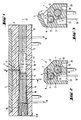
- the acceleration or deceleration sensor shown in the drawings according to FIGS. 1 to 3 is designated as a whole by (1). It consists of the housing (2), which has two mutually parallel tunnel-shaped recesses (3 and 4). The embodiments shown in cross section in FIGS. 2 and 3 each have two mutually parallel material recesses (22, 23) at the bottom; 4 there are four in total in the embodiment according to FIG.
- the permanent magnet (5) is designed as a fixed, non-displaceable permanent magnet; the permanent magnet (6) is displaceable in the illustrated embodiment.
- the permanent magnets are arranged so that two poles of the same name lie opposite one another, for example the N poles. The overall arrangement is such that the reed switch is actuated by the magnetic field when the permanent magnet (6) is displaced.
- the recess (3) which serves to receive the reed switch, is equipped according to the invention with a cover (7) which can be opened transversely to the longitudinal axis of the recess (3).
- the cover (7) is designed as a hinged cover, which is captively connected to the housing (2) via film hinges (8).
- film hinges (8) it may be advantageous to arrange a single film hinge (8) which is continuous over the entire length of the cover; or it can be advantageous to arrange several smaller film hinges one behind the other.
- the recess (4) for receiving the displaceable permanent magnet (6) is closed according to the invention on its outer end face (9) with an adjusting screw (10).
- the recess (4) which is used to hold the permanent magnets (5 and 6), is divided into two successive sub-spaces (12 and 13) by a narrowing, preferably by an intermediate wall (11) .
- One of the two permanent magnets (6 and 5) is arranged in each of these subspaces.
- the subdivision of the recess (4) into the two subspaces (12 and 13) has various advantages. On the one hand, it allows the space (13), which is used to hold the fixed permanent magnet (5), to be dimensioned such that this space corresponds exactly to the volume or dimensions of the permanent magnet (5). This fixes the position of this permanent magnet, which is very important for the accuracy of the response values.
- the subdivision further allows the space (12) to be filled with a damping liquid (20), which gives another possibility of influencing the movement behavior of the magnet (6) and thus the switching behavior of the sensor. In this case, however, it is necessary to use a slightly thinner permanent magnet or - Alternatively - to choose the inner diameter of the partial space (12) somewhat larger.
- a gap (16) for the passage of the damping fluid (20) must be present between the outer surface (14) of the displaceable permanent magnet (6) and the inner surface (15). If the permanent magnet (6) moves in the direction of the longitudinal axis (21) of the partial space (12) when an acceleration or deceleration moment occurs, the damping fluid flows through the gap (16), which is only possible relatively slowly, so that this results in braking of the permanent magnet (6) takes place. The slower movement of this permanent magnet delays the response of the sensor.
- silicone oils come into consideration, which can be selected depending on the desired viscosity. Silicone oils have the advantage over other liquids, for example paraffins, that they have a relatively low temperature coefficient of viscosity, so that sensors filled with silicone oil can be used at temperatures of approximately -40 ° C. to + 160 ° C.
- the magnetic materials that are considered here must also be selected. It is essential that the magnetic materials have a relatively low temperature coefficient of the coercive force; the level of the coercive force itself is not so important, since the reed switches to be used already react to relatively weak magnetic fields. In view of these conditions, AlNiCo magnets have proven themselves best in tests carried out accordingly.
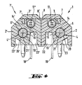
- two sensors (1 and 1 ') are arranged parallel to each other back to back.
- the construction allows the respective (7,7 ') to be opened around the hinges (8,8') and thus the access to the reed switches (17, 17 ') or to the reed switch rooms (3 and 3 ′).
Landscapes
- Physics & Mathematics (AREA)
- General Physics & Mathematics (AREA)
- Switches Operated By Changes In Physical Conditions (AREA)
- Air Bags (AREA)
- Control Of Transmission Device (AREA)
- Control Of Electric Motors In General (AREA)
- Switches That Are Operated By Magnetic Or Electric Fields (AREA)
- Control Of Motors That Do Not Use Commutators (AREA)
- Control Of Position Or Direction (AREA)
- Arrangement Or Mounting Of Propulsion Units For Vehicles (AREA)
Applications Claiming Priority (2)
| Application Number | Priority Date | Filing Date | Title |
|---|---|---|---|
| DE8806240U | 1988-05-11 | ||
| DE8806240U DE8806240U1 (de) | 1988-05-11 | 1988-05-11 | Beschleunigungs- oder Verzögerungs-Sensor |
Publications (3)
| Publication Number | Publication Date |
|---|---|
| EP0341464A2 true EP0341464A2 (fr) | 1989-11-15 |
| EP0341464A3 EP0341464A3 (en) | 1990-08-22 |
| EP0341464B1 EP0341464B1 (fr) | 1994-09-21 |
Family
ID=6823948
Family Applications (1)
| Application Number | Title | Priority Date | Filing Date |
|---|---|---|---|
| EP89107177A Expired - Lifetime EP0341464B1 (fr) | 1988-05-11 | 1989-04-21 | Senseur d'accélération ou de décélération |
Country Status (12)
| Country | Link |
|---|---|
| US (1) | US4965416A (fr) |
| EP (1) | EP0341464B1 (fr) |
| JP (1) | JPH0782793B2 (fr) |
| KR (1) | KR930004327B1 (fr) |
| AT (1) | ATE112091T1 (fr) |
| AU (1) | AU611286B2 (fr) |
| BR (1) | BR8902196A (fr) |
| CA (1) | CA1308792C (fr) |
| DE (2) | DE8806240U1 (fr) |
| MX (1) | MX171238B (fr) |
| MY (1) | MY103886A (fr) |
| PT (1) | PT90518B (fr) |
Cited By (4)
| Publication number | Priority date | Publication date | Assignee | Title |
|---|---|---|---|---|
| DE9004538U1 (de) * | 1990-04-21 | 1990-08-02 | W. Günther GmbH, 8500 Nürnberg | Bewegungs-Sensor für Bügeleisen |
| EP0498018A1 (fr) * | 1991-02-08 | 1992-08-12 | TDK Corporation | Capteur d'accélération |
| EP0545393A1 (fr) * | 1991-12-02 | 1993-06-09 | Tokin Corporation | Détecteur d'impact |
| US5248861A (en) * | 1989-08-11 | 1993-09-28 | Tdk Corporation | Acceleration sensor |
Families Citing this family (18)
| Publication number | Priority date | Publication date | Assignee | Title |
|---|---|---|---|---|
| DE8806240U1 (de) * | 1988-05-11 | 1988-08-18 | W. Günther GmbH, 8500 Nürnberg | Beschleunigungs- oder Verzögerungs-Sensor |
| US5237134A (en) * | 1989-12-06 | 1993-08-17 | Breed Automotive Technology, Inc. | Gas damped crash sensor |
| JPH0475967U (fr) * | 1990-11-13 | 1992-07-02 | ||
| US5430334A (en) * | 1990-11-19 | 1995-07-04 | Echlin, Inc. | Impact sensor for vehicle safety restraint system |
| US5608270A (en) * | 1990-11-19 | 1997-03-04 | Meister; Jack B. | Vehicle safety restraint system with linear output impact sensor |
| US5485041A (en) * | 1990-11-19 | 1996-01-16 | Meister; Jack B. | Impact sensor for vehicle safety restraint system |
| JPH04112437U (ja) * | 1991-03-19 | 1992-09-30 | 日本電気株式会社 | 衝撃センサ |
| GB9110863D0 (en) * | 1991-05-20 | 1991-07-10 | Inertia Switch Ltd | Electric switch |
| GB9112878D0 (en) * | 1991-06-14 | 1991-07-31 | Cqr Security Components Ltd | Alarm assembly |
| US5256839A (en) * | 1992-03-05 | 1993-10-26 | Shawn Gallagher | Tilt switch responsive to acceleration or deceleration |
| JPH0658370U (ja) * | 1993-01-20 | 1994-08-12 | 日本精工株式会社 | 起動装置 |
| US5416293A (en) * | 1994-08-17 | 1995-05-16 | Hamlin, Inc. | Shock sensor including a compound housing and magnetically operated reed switch |
| JPH10213591A (ja) | 1997-01-30 | 1998-08-11 | Oki Electric Ind Co Ltd | 衝撃センサ |
| US6002091A (en) * | 1998-11-18 | 1999-12-14 | Breed Automotive Technology, Inc. | Bi-directional shock sensor employing reed switch |
| DE10343588A1 (de) * | 2003-09-18 | 2005-04-14 | Vibracoustic Gmbh & Co. Kg | Buchse, insbesondere Fahrwerksbuchse, mit integriertem Drehwinkelgeber |
| US20070222249A1 (en) * | 2006-03-23 | 2007-09-27 | Jeffrey Valentage | Interior trim panel with integrated living hinged components |
| KR101348573B1 (ko) * | 2011-12-20 | 2014-01-08 | 현대다이모스(주) | 가감속 감지 장치 및 이를 포함한 차량용 안전운행 시스템 |
| US11844661B2 (en) * | 2021-03-12 | 2023-12-19 | Kurt G. Vest | Flosser |
Family Cites Families (13)
| Publication number | Priority date | Publication date | Assignee | Title |
|---|---|---|---|---|
| US2976378A (en) * | 1958-06-03 | 1961-03-21 | Lockheed Aircraft Corp | Acceleration responsive devices |
| DE1987211U (de) * | 1964-03-12 | 1968-06-12 | Robert Bosch G.m.b.H., 7000 Stuttgart | Durch einen Dauermagnet betätigter elektrischer Schalter |
| US3459911A (en) * | 1968-01-16 | 1969-08-05 | Inertia Switch Inc | Inertia switch with magnetic shunting |
| US3673527A (en) * | 1971-02-19 | 1972-06-27 | Redactron Corp | Reed switch ang magnetic over-center device therefor |
| US3877314A (en) * | 1973-03-26 | 1975-04-15 | Illinois Tool Works | Accelerometer |
| US3932718A (en) * | 1974-07-01 | 1976-01-13 | Chaim Porat | Intrusion detector |
| US4409577A (en) * | 1981-06-08 | 1983-10-11 | Sentrol, Inc. | Switch housing having recessed conductor terminals |
| DE3216321C1 (de) * | 1982-05-03 | 1983-09-29 | Daimler-Benz Ag, 7000 Stuttgart | Magnetisch betaetigter elektrischer Schalter |
| BE894273A (nl) * | 1982-09-01 | 1983-03-01 | C P Clare Internat N V | Magnetische schakelaar met vertraging |
| DE3338287C1 (de) * | 1983-10-21 | 1985-05-02 | W. Günther GmbH, 8500 Nürnberg | Beschleunigungs- und Verzoegerungs-Sensor |
| US4739135A (en) * | 1987-05-04 | 1988-04-19 | Cte Chem Tech Equipment Corp. | Attitude insensitive automatic reset flow sensor |
| DE8801694U1 (de) * | 1988-02-10 | 1988-03-31 | Kolley, Klaus-F., 70839 Gerlingen | Vorrichtung zur Beschleunigungsmessung |
| DE8806240U1 (de) * | 1988-05-11 | 1988-08-18 | W. Günther GmbH, 8500 Nürnberg | Beschleunigungs- oder Verzögerungs-Sensor |
-
1988
- 1988-05-11 DE DE8806240U patent/DE8806240U1/de not_active Expired
-
1989
- 1989-04-21 AT AT89107177T patent/ATE112091T1/de active
- 1989-04-21 EP EP89107177A patent/EP0341464B1/fr not_active Expired - Lifetime
- 1989-04-21 DE DE58908377T patent/DE58908377D1/de not_active Expired - Fee Related
- 1989-04-29 MY MYPI89000572A patent/MY103886A/en unknown
- 1989-05-04 AU AU34021/89A patent/AU611286B2/en not_active Ceased
- 1989-05-04 MX MX015937A patent/MX171238B/es unknown
- 1989-05-10 PT PT90518A patent/PT90518B/pt not_active IP Right Cessation
- 1989-05-10 KR KR1019890006226A patent/KR930004327B1/ko not_active Expired - Fee Related
- 1989-05-10 BR BR898902196A patent/BR8902196A/pt not_active IP Right Cessation
- 1989-05-10 CA CA000599330A patent/CA1308792C/fr not_active Expired - Lifetime
- 1989-05-11 JP JP1116241A patent/JPH0782793B2/ja not_active Expired - Lifetime
- 1989-05-11 US US07/350,677 patent/US4965416A/en not_active Expired - Fee Related
Cited By (4)
| Publication number | Priority date | Publication date | Assignee | Title |
|---|---|---|---|---|
| US5248861A (en) * | 1989-08-11 | 1993-09-28 | Tdk Corporation | Acceleration sensor |
| DE9004538U1 (de) * | 1990-04-21 | 1990-08-02 | W. Günther GmbH, 8500 Nürnberg | Bewegungs-Sensor für Bügeleisen |
| EP0498018A1 (fr) * | 1991-02-08 | 1992-08-12 | TDK Corporation | Capteur d'accélération |
| EP0545393A1 (fr) * | 1991-12-02 | 1993-06-09 | Tokin Corporation | Détecteur d'impact |
Also Published As
| Publication number | Publication date |
|---|---|
| EP0341464B1 (fr) | 1994-09-21 |
| US4965416A (en) | 1990-10-23 |
| KR900018683A (ko) | 1990-12-22 |
| DE58908377D1 (de) | 1994-10-27 |
| DE8806240U1 (de) | 1988-08-18 |
| JPH0782793B2 (ja) | 1995-09-06 |
| MY103886A (en) | 1993-09-30 |
| PT90518B (pt) | 1995-05-31 |
| BR8902196A (pt) | 1990-01-02 |
| ATE112091T1 (de) | 1994-10-15 |
| KR930004327B1 (ko) | 1993-05-26 |
| AU611286B2 (en) | 1991-06-06 |
| EP0341464A3 (en) | 1990-08-22 |
| MX171238B (es) | 1993-10-13 |
| JPH0221525A (ja) | 1990-01-24 |
| CA1308792C (fr) | 1992-10-13 |
| AU3402189A (en) | 1989-11-16 |
| PT90518A (pt) | 1989-11-30 |
Similar Documents
| Publication | Publication Date | Title |
|---|---|---|
| EP0341464B1 (fr) | Senseur d'accélération ou de décélération | |
| DE3338287C1 (de) | Beschleunigungs- und Verzoegerungs-Sensor | |
| DE3426014C2 (fr) | ||
| EP0405123B1 (fr) | Soupape électromagnétique à deux sens pour réglage d'une dérivation | |
| DE102018116187A1 (de) | Drehdämpfer | |
| EP0657326A1 (fr) | Arceau de sécurité pour véhicules automobiles | |
| DE3115630A1 (de) | Geschwindigkeits-aenderungssensor | |
| DE1018675B (de) | Stossdaempfer | |
| DE2751342A1 (de) | Radaggregat | |
| EP0435357A1 (fr) | Soupape de dérivation à caractéristiques variables pour amortisseurs de vibrations réglables | |
| DE102012020739A1 (de) | Luftleiteinrichtung eines Kraftfahrzeugs | |
| DE69205363T3 (de) | Sonnenblende für kraftfahrzeug. | |
| DE19859238A1 (de) | Kraftfahrzeugsitz | |
| DE2364855A1 (de) | Stossdaempfer | |
| DE2320262B2 (de) | Pneumatische stossfaengeranordnung fuer fahrzeuge | |
| DE1084528B (de) | Regelbarer hydraulischer Stossdaempfer | |
| DE3930077C2 (de) | Impulssensor | |
| DE10061030B4 (de) | Einrichtung mit einem sich um eine Achse drehenden Element | |
| DE102014112758A1 (de) | Einrichtung zum Öffnen und Schließen eines Fachs | |
| DE102018124310B4 (de) | Magnetankerventil | |
| DE10200826C1 (de) | Lenkmodul für ein Steer-by-wire-Lenksystem in Kraftfahrzeugen | |
| EP0268937B1 (fr) | Dispositif de contact électrique | |
| DE102007010628A1 (de) | Türgriffanordnung für eine Kraftfahrzeugtür o. dgl. | |
| DE102004009726B4 (de) | Vorrichtung zur Absorption von Stoßenergie in einer Kraftfahrzeuglenksäuleneinheit | |
| EP0500534B1 (fr) | Amortisseur de vibrations reglable |
Legal Events
| Date | Code | Title | Description |
|---|---|---|---|
| PUAI | Public reference made under article 153(3) epc to a published international application that has entered the european phase |
Free format text: ORIGINAL CODE: 0009012 |
|
| AK | Designated contracting states |
Kind code of ref document: A2 Designated state(s): AT BE CH DE ES FR GB GR IT LI LU NL SE |
|
| PUAL | Search report despatched |
Free format text: ORIGINAL CODE: 0009013 |
|
| AK | Designated contracting states |
Kind code of ref document: A3 Designated state(s): AT BE CH DE ES FR GB GR IT LI LU NL SE |
|
| 17P | Request for examination filed |
Effective date: 19900908 |
|
| 17Q | First examination report despatched |
Effective date: 19940207 |
|
| GRAA | (expected) grant |
Free format text: ORIGINAL CODE: 0009210 |
|
| AK | Designated contracting states |
Kind code of ref document: B1 Designated state(s): AT BE CH DE ES FR GB GR IT LI LU NL SE |
|
| PG25 | Lapsed in a contracting state [announced via postgrant information from national office to epo] |
Ref country code: NL Effective date: 19940921 Ref country code: GR Free format text: LAPSE BECAUSE OF FAILURE TO SUBMIT A TRANSLATION OF THE DESCRIPTION OR TO PAY THE FEE WITHIN THE PRESCRIBED TIME-LIMIT Effective date: 19940921 Ref country code: ES Free format text: THE PATENT HAS BEEN ANNULLED BY A DECISION OF A NATIONAL AUTHORITY Effective date: 19940921 Ref country code: BE Effective date: 19940921 |
|
| REF | Corresponds to: |
Ref document number: 112091 Country of ref document: AT Date of ref document: 19941015 Kind code of ref document: T |
|
| REF | Corresponds to: |
Ref document number: 58908377 Country of ref document: DE Date of ref document: 19941027 |
|
| ITF | It: translation for a ep patent filed | ||
| GBT | Gb: translation of ep patent filed (gb section 77(6)(a)/1977) |
Effective date: 19941215 |
|
| ET | Fr: translation filed | ||
| EAL | Se: european patent in force in sweden |
Ref document number: 89107177.1 |
|
| NLV1 | Nl: lapsed or annulled due to failure to fulfill the requirements of art. 29p and 29m of the patents act | ||
| PG25 | Lapsed in a contracting state [announced via postgrant information from national office to epo] |
Ref country code: AT Effective date: 19950421 |
|
| PG25 | Lapsed in a contracting state [announced via postgrant information from national office to epo] |
Ref country code: LU Free format text: LAPSE BECAUSE OF NON-PAYMENT OF DUE FEES Effective date: 19950430 Ref country code: LI Effective date: 19950430 Ref country code: CH Effective date: 19950430 |
|
| PLBE | No opposition filed within time limit |
Free format text: ORIGINAL CODE: 0009261 |
|
| STAA | Information on the status of an ep patent application or granted ep patent |
Free format text: STATUS: NO OPPOSITION FILED WITHIN TIME LIMIT |
|
| 26N | No opposition filed | ||
| REG | Reference to a national code |
Ref country code: CH Ref legal event code: PL |
|
| PGFP | Annual fee paid to national office [announced via postgrant information from national office to epo] |
Ref country code: SE Payment date: 19960419 Year of fee payment: 8 |
|
| PG25 | Lapsed in a contracting state [announced via postgrant information from national office to epo] |
Ref country code: SE Effective date: 19970422 |
|
| EUG | Se: european patent has lapsed |
Ref document number: 89107177.1 |
|
| PGFP | Annual fee paid to national office [announced via postgrant information from national office to epo] |
Ref country code: GB Payment date: 20000403 Year of fee payment: 12 |
|
| PGFP | Annual fee paid to national office [announced via postgrant information from national office to epo] |
Ref country code: FR Payment date: 20000417 Year of fee payment: 12 |
|
| PGFP | Annual fee paid to national office [announced via postgrant information from national office to epo] |
Ref country code: DE Payment date: 20010411 Year of fee payment: 13 |
|
| PG25 | Lapsed in a contracting state [announced via postgrant information from national office to epo] |
Ref country code: GB Free format text: LAPSE BECAUSE OF NON-PAYMENT OF DUE FEES Effective date: 20010421 |
|
| PG25 | Lapsed in a contracting state [announced via postgrant information from national office to epo] |
Ref country code: FR Free format text: THE PATENT HAS BEEN ANNULLED BY A DECISION OF A NATIONAL AUTHORITY Effective date: 20010430 |
|
| GBPC | Gb: european patent ceased through non-payment of renewal fee |
Effective date: 20010421 |
|
| REG | Reference to a national code |
Ref country code: FR Ref legal event code: ST |
|
| PG25 | Lapsed in a contracting state [announced via postgrant information from national office to epo] |
Ref country code: DE Free format text: LAPSE BECAUSE OF NON-PAYMENT OF DUE FEES Effective date: 20021101 |
|
| PG25 | Lapsed in a contracting state [announced via postgrant information from national office to epo] |
Ref country code: IT Free format text: LAPSE BECAUSE OF NON-PAYMENT OF DUE FEES;WARNING: LAPSES OF ITALIAN PATENTS WITH EFFECTIVE DATE BEFORE 2007 MAY HAVE OCCURRED AT ANY TIME BEFORE 2007. THE CORRECT EFFECTIVE DATE MAY BE DIFFERENT FROM THE ONE RECORDED. Effective date: 20050421 |