EP0341235A2 - Schweissmaschine zum Stumpfschweissen von Kunststoffprofilen - Google Patents
Schweissmaschine zum Stumpfschweissen von Kunststoffprofilen Download PDFInfo
- Publication number
- EP0341235A2 EP0341235A2 EP89890127A EP89890127A EP0341235A2 EP 0341235 A2 EP0341235 A2 EP 0341235A2 EP 89890127 A EP89890127 A EP 89890127A EP 89890127 A EP89890127 A EP 89890127A EP 0341235 A2 EP0341235 A2 EP 0341235A2
- Authority
- EP
- European Patent Office
- Prior art keywords
- profiles
- clamping
- clamping units
- welding
- profile
- Prior art date
- Legal status (The legal status is an assumption and is not a legal conclusion. Google has not performed a legal analysis and makes no representation as to the accuracy of the status listed.)
- Granted
Links
Images


Classifications
-
- B—PERFORMING OPERATIONS; TRANSPORTING
- B29—WORKING OF PLASTICS; WORKING OF SUBSTANCES IN A PLASTIC STATE IN GENERAL
- B29C—SHAPING OR JOINING OF PLASTICS; SHAPING OF MATERIAL IN A PLASTIC STATE, NOT OTHERWISE PROVIDED FOR; AFTER-TREATMENT OF THE SHAPED PRODUCTS, e.g. REPAIRING
- B29C66/00—General aspects of processes or apparatus for joining preformed parts
- B29C66/50—General aspects of joining tubular articles; General aspects of joining long products, i.e. bars or profiled elements; General aspects of joining single elements to tubular articles, hollow articles or bars; General aspects of joining several hollow-preforms to form hollow or tubular articles
- B29C66/51—Joining tubular articles, profiled elements or bars; Joining single elements to tubular articles, hollow articles or bars; Joining several hollow-preforms to form hollow or tubular articles
- B29C66/52—Joining tubular articles, bars or profiled elements
- B29C66/524—Joining profiled elements
- B29C66/5243—Joining profiled elements for forming corner connections, e.g. for making window frames or V-shaped pieces
- B29C66/52431—Joining profiled elements for forming corner connections, e.g. for making window frames or V-shaped pieces with a right angle, e.g. for making L-shaped pieces
-
- B—PERFORMING OPERATIONS; TRANSPORTING
- B29—WORKING OF PLASTICS; WORKING OF SUBSTANCES IN A PLASTIC STATE IN GENERAL
- B29C—SHAPING OR JOINING OF PLASTICS; SHAPING OF MATERIAL IN A PLASTIC STATE, NOT OTHERWISE PROVIDED FOR; AFTER-TREATMENT OF THE SHAPED PRODUCTS, e.g. REPAIRING
- B29C65/00—Joining or sealing of preformed parts, e.g. welding of plastics materials; Apparatus therefor
- B29C65/02—Joining or sealing of preformed parts, e.g. welding of plastics materials; Apparatus therefor by heating, with or without pressure
- B29C65/18—Joining or sealing of preformed parts, e.g. welding of plastics materials; Apparatus therefor by heating, with or without pressure using heated tools
- B29C65/20—Joining or sealing of preformed parts, e.g. welding of plastics materials; Apparatus therefor by heating, with or without pressure using heated tools with direct contact, e.g. using "mirror"
- B29C65/2007—Joining or sealing of preformed parts, e.g. welding of plastics materials; Apparatus therefor by heating, with or without pressure using heated tools with direct contact, e.g. using "mirror" characterised by the type of welding mirror
- B29C65/203—Joining or sealing of preformed parts, e.g. welding of plastics materials; Apparatus therefor by heating, with or without pressure using heated tools with direct contact, e.g. using "mirror" characterised by the type of welding mirror being several single mirrors, e.g. not mounted on the same tool
-
- B—PERFORMING OPERATIONS; TRANSPORTING
- B29—WORKING OF PLASTICS; WORKING OF SUBSTANCES IN A PLASTIC STATE IN GENERAL
- B29C—SHAPING OR JOINING OF PLASTICS; SHAPING OF MATERIAL IN A PLASTIC STATE, NOT OTHERWISE PROVIDED FOR; AFTER-TREATMENT OF THE SHAPED PRODUCTS, e.g. REPAIRING
- B29C65/00—Joining or sealing of preformed parts, e.g. welding of plastics materials; Apparatus therefor
- B29C65/02—Joining or sealing of preformed parts, e.g. welding of plastics materials; Apparatus therefor by heating, with or without pressure
- B29C65/18—Joining or sealing of preformed parts, e.g. welding of plastics materials; Apparatus therefor by heating, with or without pressure using heated tools
- B29C65/20—Joining or sealing of preformed parts, e.g. welding of plastics materials; Apparatus therefor by heating, with or without pressure using heated tools with direct contact, e.g. using "mirror"
- B29C65/2053—Joining or sealing of preformed parts, e.g. welding of plastics materials; Apparatus therefor by heating, with or without pressure using heated tools with direct contact, e.g. using "mirror" characterised by special ways of bringing the welding mirrors into position
- B29C65/2061—Joining or sealing of preformed parts, e.g. welding of plastics materials; Apparatus therefor by heating, with or without pressure using heated tools with direct contact, e.g. using "mirror" characterised by special ways of bringing the welding mirrors into position by sliding
- B29C65/2069—Joining or sealing of preformed parts, e.g. welding of plastics materials; Apparatus therefor by heating, with or without pressure using heated tools with direct contact, e.g. using "mirror" characterised by special ways of bringing the welding mirrors into position by sliding with an angle with respect to the plane comprising the parts to be joined
- B29C65/2076—Joining or sealing of preformed parts, e.g. welding of plastics materials; Apparatus therefor by heating, with or without pressure using heated tools with direct contact, e.g. using "mirror" characterised by special ways of bringing the welding mirrors into position by sliding with an angle with respect to the plane comprising the parts to be joined perpendicularly to the plane comprising the parts to be joined
-
- B—PERFORMING OPERATIONS; TRANSPORTING
- B29—WORKING OF PLASTICS; WORKING OF SUBSTANCES IN A PLASTIC STATE IN GENERAL
- B29C—SHAPING OR JOINING OF PLASTICS; SHAPING OF MATERIAL IN A PLASTIC STATE, NOT OTHERWISE PROVIDED FOR; AFTER-TREATMENT OF THE SHAPED PRODUCTS, e.g. REPAIRING
- B29C65/00—Joining or sealing of preformed parts, e.g. welding of plastics materials; Apparatus therefor
- B29C65/78—Means for handling the parts to be joined, e.g. for making containers or hollow articles, e.g. means for handling sheets, plates, web-like materials, tubular articles, hollow articles or elements to be joined therewith; Means for discharging the joined articles from the joining apparatus
- B29C65/7802—Positioning the parts to be joined, e.g. aligning, indexing or centring
- B29C65/782—Positioning the parts to be joined, e.g. aligning, indexing or centring by setting the gap between the parts to be joined
-
- B—PERFORMING OPERATIONS; TRANSPORTING
- B29—WORKING OF PLASTICS; WORKING OF SUBSTANCES IN A PLASTIC STATE IN GENERAL
- B29C—SHAPING OR JOINING OF PLASTICS; SHAPING OF MATERIAL IN A PLASTIC STATE, NOT OTHERWISE PROVIDED FOR; AFTER-TREATMENT OF THE SHAPED PRODUCTS, e.g. REPAIRING
- B29C65/00—Joining or sealing of preformed parts, e.g. welding of plastics materials; Apparatus therefor
- B29C65/78—Means for handling the parts to be joined, e.g. for making containers or hollow articles, e.g. means for handling sheets, plates, web-like materials, tubular articles, hollow articles or elements to be joined therewith; Means for discharging the joined articles from the joining apparatus
- B29C65/7802—Positioning the parts to be joined, e.g. aligning, indexing or centring
- B29C65/7835—Positioning the parts to be joined, e.g. aligning, indexing or centring by using stops
-
- B—PERFORMING OPERATIONS; TRANSPORTING
- B29—WORKING OF PLASTICS; WORKING OF SUBSTANCES IN A PLASTIC STATE IN GENERAL
- B29C—SHAPING OR JOINING OF PLASTICS; SHAPING OF MATERIAL IN A PLASTIC STATE, NOT OTHERWISE PROVIDED FOR; AFTER-TREATMENT OF THE SHAPED PRODUCTS, e.g. REPAIRING
- B29C65/00—Joining or sealing of preformed parts, e.g. welding of plastics materials; Apparatus therefor
- B29C65/78—Means for handling the parts to be joined, e.g. for making containers or hollow articles, e.g. means for handling sheets, plates, web-like materials, tubular articles, hollow articles or elements to be joined therewith; Means for discharging the joined articles from the joining apparatus
- B29C65/7841—Holding or clamping means for handling purposes
-
- B—PERFORMING OPERATIONS; TRANSPORTING
- B29—WORKING OF PLASTICS; WORKING OF SUBSTANCES IN A PLASTIC STATE IN GENERAL
- B29C—SHAPING OR JOINING OF PLASTICS; SHAPING OF MATERIAL IN A PLASTIC STATE, NOT OTHERWISE PROVIDED FOR; AFTER-TREATMENT OF THE SHAPED PRODUCTS, e.g. REPAIRING
- B29C66/00—General aspects of processes or apparatus for joining preformed parts
- B29C66/01—General aspects dealing with the joint area or with the area to be joined
- B29C66/05—Particular design of joint configurations
- B29C66/10—Particular design of joint configurations particular design of the joint cross-sections
- B29C66/11—Joint cross-sections comprising a single joint-segment, i.e. one of the parts to be joined comprising a single joint-segment in the joint cross-section
- B29C66/116—Single bevelled joints, i.e. one of the parts to be joined being bevelled in the joint area
- B29C66/1162—Single bevel to bevel joints, e.g. mitre joints
-
- B—PERFORMING OPERATIONS; TRANSPORTING
- B29—WORKING OF PLASTICS; WORKING OF SUBSTANCES IN A PLASTIC STATE IN GENERAL
- B29C—SHAPING OR JOINING OF PLASTICS; SHAPING OF MATERIAL IN A PLASTIC STATE, NOT OTHERWISE PROVIDED FOR; AFTER-TREATMENT OF THE SHAPED PRODUCTS, e.g. REPAIRING
- B29C66/00—General aspects of processes or apparatus for joining preformed parts
- B29C66/70—General aspects of processes or apparatus for joining preformed parts characterised by the composition, physical properties or the structure of the material of the parts to be joined; Joining with non-plastics material
- B29C66/72—General aspects of processes or apparatus for joining preformed parts characterised by the composition, physical properties or the structure of the material of the parts to be joined; Joining with non-plastics material characterised by the structure of the material of the parts to be joined
- B29C66/725—General aspects of processes or apparatus for joining preformed parts characterised by the composition, physical properties or the structure of the material of the parts to be joined; Joining with non-plastics material characterised by the structure of the material of the parts to be joined being hollow-walled or honeycombs
- B29C66/7252—General aspects of processes or apparatus for joining preformed parts characterised by the composition, physical properties or the structure of the material of the parts to be joined; Joining with non-plastics material characterised by the structure of the material of the parts to be joined being hollow-walled or honeycombs hollow-walled
- B29C66/72523—General aspects of processes or apparatus for joining preformed parts characterised by the composition, physical properties or the structure of the material of the parts to be joined; Joining with non-plastics material characterised by the structure of the material of the parts to be joined being hollow-walled or honeycombs hollow-walled multi-channelled or multi-tubular
-
- B—PERFORMING OPERATIONS; TRANSPORTING
- B29—WORKING OF PLASTICS; WORKING OF SUBSTANCES IN A PLASTIC STATE IN GENERAL
- B29C—SHAPING OR JOINING OF PLASTICS; SHAPING OF MATERIAL IN A PLASTIC STATE, NOT OTHERWISE PROVIDED FOR; AFTER-TREATMENT OF THE SHAPED PRODUCTS, e.g. REPAIRING
- B29C66/00—General aspects of processes or apparatus for joining preformed parts
- B29C66/70—General aspects of processes or apparatus for joining preformed parts characterised by the composition, physical properties or the structure of the material of the parts to be joined; Joining with non-plastics material
- B29C66/73—General aspects of processes or apparatus for joining preformed parts characterised by the composition, physical properties or the structure of the material of the parts to be joined; Joining with non-plastics material characterised by the intensive physical properties of the material of the parts to be joined, by the optical properties of the material of the parts to be joined, by the extensive physical properties of the parts to be joined, by the state of the material of the parts to be joined or by the material of the parts to be joined being a thermoplastic or a thermoset
- B29C66/739—General aspects of processes or apparatus for joining preformed parts characterised by the composition, physical properties or the structure of the material of the parts to be joined; Joining with non-plastics material characterised by the intensive physical properties of the material of the parts to be joined, by the optical properties of the material of the parts to be joined, by the extensive physical properties of the parts to be joined, by the state of the material of the parts to be joined or by the material of the parts to be joined being a thermoplastic or a thermoset characterised by the material of the parts to be joined being a thermoplastic or a thermoset
- B29C66/7392—General aspects of processes or apparatus for joining preformed parts characterised by the composition, physical properties or the structure of the material of the parts to be joined; Joining with non-plastics material characterised by the intensive physical properties of the material of the parts to be joined, by the optical properties of the material of the parts to be joined, by the extensive physical properties of the parts to be joined, by the state of the material of the parts to be joined or by the material of the parts to be joined being a thermoplastic or a thermoset characterised by the material of the parts to be joined being a thermoplastic or a thermoset characterised by the material of at least one of the parts being a thermoplastic
- B29C66/73921—General aspects of processes or apparatus for joining preformed parts characterised by the composition, physical properties or the structure of the material of the parts to be joined; Joining with non-plastics material characterised by the intensive physical properties of the material of the parts to be joined, by the optical properties of the material of the parts to be joined, by the extensive physical properties of the parts to be joined, by the state of the material of the parts to be joined or by the material of the parts to be joined being a thermoplastic or a thermoset characterised by the material of the parts to be joined being a thermoplastic or a thermoset characterised by the material of at least one of the parts being a thermoplastic characterised by the materials of both parts being thermoplastics
-
- B—PERFORMING OPERATIONS; TRANSPORTING
- B29—WORKING OF PLASTICS; WORKING OF SUBSTANCES IN A PLASTIC STATE IN GENERAL
- B29C—SHAPING OR JOINING OF PLASTICS; SHAPING OF MATERIAL IN A PLASTIC STATE, NOT OTHERWISE PROVIDED FOR; AFTER-TREATMENT OF THE SHAPED PRODUCTS, e.g. REPAIRING
- B29C66/00—General aspects of processes or apparatus for joining preformed parts
- B29C66/80—General aspects of machine operations or constructions and parts thereof
- B29C66/84—Specific machine types or machines suitable for specific applications
- B29C66/843—Machines for making separate joints at the same time in different planes; Machines for making separate joints at the same time mounted in parallel or in series
- B29C66/8432—Machines for making separate joints at the same time mounted in parallel or in series
-
- B—PERFORMING OPERATIONS; TRANSPORTING
- B29—WORKING OF PLASTICS; WORKING OF SUBSTANCES IN A PLASTIC STATE IN GENERAL
- B29C—SHAPING OR JOINING OF PLASTICS; SHAPING OF MATERIAL IN A PLASTIC STATE, NOT OTHERWISE PROVIDED FOR; AFTER-TREATMENT OF THE SHAPED PRODUCTS, e.g. REPAIRING
- B29C65/00—Joining or sealing of preformed parts, e.g. welding of plastics materials; Apparatus therefor
- B29C65/02—Joining or sealing of preformed parts, e.g. welding of plastics materials; Apparatus therefor by heating, with or without pressure
- B29C65/18—Joining or sealing of preformed parts, e.g. welding of plastics materials; Apparatus therefor by heating, with or without pressure using heated tools
- B29C65/24—Joining or sealing of preformed parts, e.g. welding of plastics materials; Apparatus therefor by heating, with or without pressure using heated tools characterised by the means for heating the tool
- B29C65/30—Electrical means
- B29C65/305—Electrical means involving the use of cartridge heaters
-
- B—PERFORMING OPERATIONS; TRANSPORTING
- B29—WORKING OF PLASTICS; WORKING OF SUBSTANCES IN A PLASTIC STATE IN GENERAL
- B29C—SHAPING OR JOINING OF PLASTICS; SHAPING OF MATERIAL IN A PLASTIC STATE, NOT OTHERWISE PROVIDED FOR; AFTER-TREATMENT OF THE SHAPED PRODUCTS, e.g. REPAIRING
- B29C66/00—General aspects of processes or apparatus for joining preformed parts
- B29C66/70—General aspects of processes or apparatus for joining preformed parts characterised by the composition, physical properties or the structure of the material of the parts to be joined; Joining with non-plastics material
- B29C66/71—General aspects of processes or apparatus for joining preformed parts characterised by the composition, physical properties or the structure of the material of the parts to be joined; Joining with non-plastics material characterised by the composition of the plastics material of the parts to be joined
-
- B—PERFORMING OPERATIONS; TRANSPORTING
- B29—WORKING OF PLASTICS; WORKING OF SUBSTANCES IN A PLASTIC STATE IN GENERAL
- B29L—INDEXING SCHEME ASSOCIATED WITH SUBCLASS B29C, RELATING TO PARTICULAR ARTICLES
- B29L2031/00—Other particular articles
- B29L2031/001—Profiled members, e.g. beams, sections
- B29L2031/003—Profiled members, e.g. beams, sections having a profiled transverse cross-section
- B29L2031/005—Profiled members, e.g. beams, sections having a profiled transverse cross-section for making window frames
-
- Y—GENERAL TAGGING OF NEW TECHNOLOGICAL DEVELOPMENTS; GENERAL TAGGING OF CROSS-SECTIONAL TECHNOLOGIES SPANNING OVER SEVERAL SECTIONS OF THE IPC; TECHNICAL SUBJECTS COVERED BY FORMER USPC CROSS-REFERENCE ART COLLECTIONS [XRACs] AND DIGESTS
- Y10—TECHNICAL SUBJECTS COVERED BY FORMER USPC
- Y10T—TECHNICAL SUBJECTS COVERED BY FORMER US CLASSIFICATION
- Y10T156/00—Adhesive bonding and miscellaneous chemical manufacture
- Y10T156/17—Surface bonding means and/or assemblymeans with work feeding or handling means
- Y10T156/1702—For plural parts or plural areas of single part
- Y10T156/1744—Means bringing discrete articles into assembled relationship
- Y10T156/1746—Plural lines and/or separate means assembling separate sandwiches
-
- Y—GENERAL TAGGING OF NEW TECHNOLOGICAL DEVELOPMENTS; GENERAL TAGGING OF CROSS-SECTIONAL TECHNOLOGIES SPANNING OVER SEVERAL SECTIONS OF THE IPC; TECHNICAL SUBJECTS COVERED BY FORMER USPC CROSS-REFERENCE ART COLLECTIONS [XRACs] AND DIGESTS
- Y10—TECHNICAL SUBJECTS COVERED BY FORMER USPC
- Y10T—TECHNICAL SUBJECTS COVERED BY FORMER US CLASSIFICATION
- Y10T29/00—Metal working
- Y10T29/53—Means to assemble or disassemble
- Y10T29/53978—Means to assemble or disassemble including means to relatively position plural work parts
Definitions
- the invention relates to a welding machine for butt welding plastic profiles, in particular window frame profiles, with profile clamping units which can be displaced relative to one another and a heating mirror which can be inserted between the end faces of two profiles to be welded, the clamping units comprising weld limit knives which can be placed on the profiles and are oriented parallel to the profile end faces.
- Profiles made of thermoplastic materials are used for the production of windows, doors, frames and.
- PVC polyvinyl chloride
- the weld seam limit knives arranged at a suitable distance from the profile end faces ensure a clean weld seam formation and limit the joining path that occurs when the profile end faces are pressed together and that is necessary for a proper weld connection.
- two or four welded connections can be made at the same time, but which welded connections must be on the same workpiece.
- An exact mutual coordination of two related workpieces for example the coordination of sash and floor frames of a window or a door has therefore been impossible until now because of the unavoidable manufacturing tolerances in the butt welding of the profiles and, in addition, the welding capacity of the known welding machines remains solely due to the times to be observed the heating, pressing and cooling of the profiles is limited.
- the invention is therefore based on the object of eliminating these deficiencies and of creating a welding machine of the type described at the outset which ensures particularly efficient butt welding of plastic profiles and moreover enables the production of workpieces which are precisely associated with one another.
- the invention solves this problem in that the clamping units for receiving two superimposed profiles, preferably a sash and a cane or frame profile, are intended and in addition to the outer limit knives an intermediate limit knife that can be inserted between the profiles and resilient in the tensioning direction of the profiles compliant and in Moving direction supported with the clamping units movable. Since each clamping unit can clamp two profiles, two welding connections can be made per welding head with little extra effort instead of one at the same time, whereby exactly the same conditions apply to both welding connections with regard to heat treatment, pressurization, welding times and, above all, welding and joining paths, and therefore through welding two precisely coordinated workpieces are also created.
- the intermediate delimiting knife ensures proper weld seam formation even in the side areas between the profiles, whereby the flexibility of the knife support guarantees a perfect clamping of both profiles, so that despite the achievable doubling of the welding capacity, there is no risk of deterioration in the welding quality.
- one of the intermediate limiting knives of two clamping units assigned to one another is fixed and the other is displaceable against the force of a return spring on a common carrier rail which runs parallel to the clamping plane and preferably parallel to one of the profiles and which in turn rests against the Force of a support spring is movable normal to the clamping plane on a bearing block connected to the one clamping unit, the other clamping unit having a driver for the displaceable intermediate limiting knife.
- the driver consists of an eccentric that can be rotated about a normal axis to the clamping plane
- the driving range can be varied by adjusting this eccentric, thus adapting the intermediate delimiter to different profile dimensions or preselecting the distance of the intermediate delimiter from the profile end face.
- the bearing block is fastened to a lifting cylinder which is preferably aligned parallel to the profile end faces and is supported on the clamping unit by a bracket or the like, as a result of which extending and retracting the lifting cylinder positions the intermediate limiting knives or in a release position for free insertion and removing the profiles.
- two stacked stop pins which can be extended and retracted by means of lifting cylinders, can also be supported on the console for determining the insertion position of the profiles lying one on top of the other.
- These stop pins allow the desired starting positions for all profiles to be maintained when inserting and clamping the profiles to be welded, so that a uniform welding of the profiles arranged one above the other is ensured.
- a welding head 1 of a two- or four-head welding machine (not shown further) for butt welding plastic profiles has two profile clamping units 2, 3, which are offset by 90 ° to one another, and which consist of a support plate 2a, 3a with a lower weld limit knife 2b, 3b and one relative to it Support plate 2a, 3a displaceable clamping slide 2c, 3c, which carriage receives a pressure plate 2e, 3e which can be pressurized via a clamping cylinder 2d, 3d with an upper seam limit knife 2f, 3f.
- One clamping unit 2 is fixedly mounted on the machine frame 1a, while the other clamping unit 3 is slidably mounted on the machine frame 1a.
- the two clamping units 2, 3 are each suitable for clamping two superimposed profiles U, O, whereby an intermediate delimitation device 4 is provided, the two intermediate delimitation knives 5 assigned to the clamping units 2, 3 and insertable between the profiles U, O to be placed on top of each other , 6 includes.
- the intermediate limiting knife 5 is firmly seated on a support rail 7 which is parallel to the clamping unit 3 and which in turn counteracts the force of a support spring 7a in the direction of action of the Spannzy Linder 2d, 3d is movably supported in a bearing block 8, and the other intermediate limiting knife 6 is guided on the carrier rail 7 so as to be longitudinally displaceable against the force of a return spring 9.
- the bearing block 8 is arranged via a lifting cylinder 10 in the direction of the intermediate limiting knives 5, 6 and can be moved in and out on a bracket 11 with which the entire intermediate limiting knife device 4 is firmly connected to the clamping unit 2.
- the other clamping unit 3 has a driver 12, which consists of a rotationally adjustable eccentric 13 projecting from the support plate 3a.
- stop pins 14 which are arranged above and below these knives are supported on the bracket 11 and can be advanced and retracted parallel to the bearing block 8 by means of their own lifting cylinders 14a.
- the welding head 1 ensures a particularly efficient butt welding of plastic profiles, since it allows the simultaneous establishment of two welded connections for superimposed profiles U, O, so that, above all, related workpieces, such as sash and stick frames of windows or doors, simultaneously and therefore also exactly one on top of the other can be manufactured in a coordinated manner.
- the clamping units 2, 3 To insert the profiles to be welded, the clamping units 2, 3 have moved apart into their insertion position and the slides 2c, 3c are in the retracted position.
- the intermediate limit knives 5, 6 are retracted when the lifting cylinder 10 is retracted, so that the lower profiles U, for example the profiles for a casement, can be inserted freely into the clamping units 2, 3, the extended stop pins 14 ensuring exact compliance with the Allow clamping position.
- the intermediate limiting knives 5, 6 extend and lie on the lower, already inserted profiles U at a desired distance from the miter cut end faces (FIG. 2).
- the next two profiles O for example the profiles of a floor frame, can be placed on the lower profiles U and the intermediate limiting knives 5, 6, the upper stop pin 14 again determining the exact clamping position.
- the carriages 2c, 3c advance to the clamping position and by acting on the clamping cylinders 2d, 3d, the profiles U, O become between the support plates 2a, 3a with the lower weld limit knives 2b, 3b on the one hand and the pressure plates 2e, 3e with the upper limit knives 2f, 3f on the other hand and the intermediate limit knives 5, 6 which yield to the required extent.
- the stop pins 14 move back and free the space between the profile end faces, so that the heating mirror 15 arranged below the clamping units 2, 3 can be inserted between the profiles U, O.
- the clamping unit 3 is pushed forward and presses the profile end faces against the heating mirror 15 until the plastic is correspondingly plasticized, then after the clamping unit 3 has been retracted, the heating mirror 15 lowers again and the clamping unit 3 is pressed forward again for the actual welding process, so that the profiles U , O are pressed together directly with their plasticized end faces.
- the driver 12 which bears against the displaceable intermediate limiting knife 6, also moves this intermediate limiting knife 6 with the profiles U, O stretched in the clamping unit 3.
- End position and driving range of the intermediate limiting knife 6 are included adjustable by turning the driver eccentric 13.
- the clamping cylinders 2d, 3d are relieved, the clamping units 2, 3 open and move back into the starting position.
- the welded upper profiles O can be freely removed from the welding head 1, whereupon the intermediate limiting knives 5, 6 are withdrawn and the lower profiles U welded to one another are also easy to remove.
Landscapes
- Engineering & Computer Science (AREA)
- Mechanical Engineering (AREA)
- Lining Or Joining Of Plastics Or The Like (AREA)
- Medicines That Contain Protein Lipid Enzymes And Other Medicines (AREA)
Abstract
Description
- Die Erfindung bezieht sich auf eine Schweißmaschine zum Stumpfschweißen von Kunststoffprofilen, insbesondere Fensterrahmenprofile, mit relativ zueinander verschiebbaren Profilaufspanneinheiten und einem zwischen die Stirnflächen zweier zu verschweißender Profile einführbaren Heizspiegel, wobei die Aufspanneinheiten auf die Profile aufsetzbare, zu den Profilstirnflächen parallelgerichtete Schweißnaht-Begrenzungsmesser umfassen.
- Profile aus thermoplastischen Kunststoffen, vorzugsweise extrudierte Polyvinylchlorid (PVC)-Profile werden zur Herstellung von Fenstern, Türen, Rahmen u. dgl. Bauteilen allgemein durch Stumpfschweißen miteinander verbunden, wozu es bereits Zwei- oder Vierkopfschweißmaschinen verschiedener Ausführungen gibt. In diesen Schweißmaschinen werden pro Schweißkopf zwei Profile miteinander verschweißt, wobei die in den Profilaufspanneinheiten festgeklemmten Profile durch entsprechendes Verschieben der Profilaufspanneinheiten stirnseitig an einen in den Vorschubweg der Aufspanneinheiten eingebrachten Heizspiegel bis zum Anschmelzen angedrückt und dann nach Entfernen des Heizspiegels die plastifizierten Profilstirnflächen zusammengepreßt werden. Die mit geeignetem Abstand von den Profilstirnflächen angeordneten Schweißnaht- Begrenzungsmesser sorgen für eine saubere Schweißnahtausbildung und begrenzen den beim Zusammenpressen der Profilstirnflächen auftretenden, für eine ordnungsgemäße Schweißverbindung erforderlichen Fügeweg. Je nach Anzahl der Schweißköpfe lassen sich so zwei oder vier Schweißverbindungen gleichzeitig herstellen, welche Schweißverbindungen aber an ein und demselben Werkstück sitzen müssen. Ein exaktes gegenseitiges Abstimmen zweier zusammengehöriger Werkstücke, beispielsweise das Abstimmen von Flügel- und Stockrahmen eines Fensters oder einer Tür ist wegen der nicht zu vermeidenden Herstellungstoleranzen beim Stumpfschweißen der Profile daher bisher unmöglich und außerdem bleibt die Schweißkapazität der bekannten Schweißmaschinen allein auf Grund der einzuhaltenden Zeiten für das Anwärmen, Zusammenpressen und Abkühlen der Profile beschränkt.
- Der Erfindung liegt daher die Aufgabe zugrunde, diese Mängel zu beseitigen und eine Schweißmaschine der eingangs geschilderten Art zu schaffen, die ein besonders rationelles Stumpfschweißen von Kunststoffprofilen gewährleistet und darüber hinaus die Herstellung exakt einander zugeordneter Werkstücke ermöglicht.
- Die Erfindung löst diese Aufgabe dadurch, daß die Aufspanneinheiten zur Aufnahme zweier übereinanderliegender Profile, vorzugsweise ein Flügel- und ein Stock- oder Blendrahmenprofil, bestimmt sind und zusätzlich zu den äußeren Begrenzungsmessern ein zwischen die Profile einlegbares Zwischenbegrenzungsmesser aufweisen, das sich in Spannrichtung der Profile federnd nachgiebig und in Verschieberichtung mit den Aufspanneinheiten mitbewegbar abstützt. Da jede Aufspanneinheit zwei Profile spannen kann, lassen sich pro Schweißkopf mit wenig Mehraufwand statt einer gleichzeitig zwei Schweißverbindungen herstellen, wobei für beide Schweißverbindungen genau die gleichen Bedingungen hinsichtlich Wärmebehandlung, Druckbeaufschlagung, Schweißzeiten und vor allem auch Schweiß- und Fügewege gelten und daher durch das Schweißen auch zwei genau aufeinander abgestimmte Werkstücke entstehen. Das Zwischenbegrenzungsmesser sorgt für eine ordnungsgemäße Schweißnahtausbildung auch in den zwischen den Profilen liegenden Seitenbereichen, wobei die Nachgiebigkeit der Messerabstützung ein einwandfreies Aufspannen beider Profile garantiert, so daß trotz der erreichbaren Verdoppelung der Schweißkapazität keine Beeinträchtigung der Schweißqualität zu befürchten ist.
- Eine besonders zweckmäßige Konstruktion ergibt sich, wenn erfindungsgemäß das eine der Zwischenbegrenzungsmesser zweier einander zugeordneter Aufspanneinheiten fest und das andere gegen die Kraft einer Rückstellfeder verschiebbar auf einer gemeinsamen, parallel zur Aufspannebene und vorzugsweise parallel zu einem der Profile verlaufenden Trägerschiene sitzen, die sich ihrerseits gegen die Kraft einer Stützfeder normal zur Aufspannebene bewegbar an einem mit der einen Aufspanneinheit verbundenen Lagerbock abstützt, wobei die andere Aufspanneinheit einen Mitnehmer für das verschiebbare Zwischenbegrenzungsmesser aufweist. Durch dieses Zusammenfassen beider Zwischenbegrenzungsmesser braucht jeweils nur eine der Aufspanneinheiten mit den Zwischenbegrenzungsmessern ausgestattet zu sein, so daß sich vor allem eine günstige Raumausnützung und eine einfache Mitnahme der Zwischenbegrenzungsmesser einerseits durch die tragende Auf spanneinheit selbst, anderseits durch einen geeigneten Mitnehmer der anderen Aufspanneinheit ergeben.
- Besteht dabei der Mitnehmer aus einem um eine Normalachse zur Aufspannebene drehverstellbaren Exzenter, kann durch Verstellen dieses Exzenters der Mitnahmebereich variiert und damit die Zwischenbegrenzungsmesser an unterschiedliche Profildimensionen angepaßt bzw. der Abstand des Zwischenbegrenzungsmessers von der Profilstirnfläche vorgewählt werden.
- Gemäß einer günstigen Weiterbildung der Erfindung ist der Lagerbock an einem vorzugsweise parallel zu den Profilstirnflächen ausgerichteten, über eine Konsole od. dgl. an der Aufspanneinheit abgestützten Hubzylinder befestigt, wodurch ein Aus- und Einfahren des Hubzylinders die Zwischenbegrenzungsmesser positioniert oder in eine Freigabestellung zum freien Einlegen und Entnehmen der Profile bringt.
- Erfindungsgemäß können an der Konsole auch zwei übereinander angeordnete, mittels Hubzylinder aus- und einfahrbare Anschlagstifte zur Bestimmung der Einlegeposition der aufeinanderliegenden Profile abgestützt sein. Diese Anschlagstifte erlauben beim Einlegen und Aufspannen der zu verschweißenden Profile das Einhalten der gewünschten Ausgangspositionen für alle Profile, so daß ein gleichmäßiges Verschweißen der übereinander angeordneten Profile gewährleistet ist.
- In der Zeichnung ist der Erfindungsgegenstand in einem Ausführungsbeispiel rein schematisch dargestellt, und zwar zeigen
- Fig. 1 und 2 einen Schweißkopf einer erfindungsgemäßen Schweißmaschine in teilgeschnittener Seitenansicht bzw. in Draufsicht,
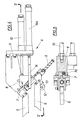
- Fig. 3 und 4 die Zwischenbegrenzungsmesser-Einrichtung dieses Schweißkopfes in Seitenansicht bzw. Draufsicht und
- Fig. 5 einen Schnitt nach der Linie V-V der Fig. 4.
- Ein Schweißkopf 1 einer nicht weiter dargestellten Zwei- oder Vierkopfschweißmaschine zum Stumpfschweißen von Kunststoffprofilen weist zwei um 90° zueinander winkelversetzt ausgerichtete Profilaufspanneinheiten 2, 3 auf, die aus einer Auflagerplatte 2a, 3a mit einem unteren Schweißnaht-Begrenzungsmesser 2b, 3b und aus einem relativ zur Auflagerplatte 2a, 3a verschiebbaren Spannschlitten 2c, 3c bestehen, welcher Schlitten eine über einen Spannzylinder 2d, 3d druckbeaufschlagbare Druckplatte 2e, 3e mit einem oberen Schweißnaht-Begrenzungsmesser 2f, 3f aufnimmt. Die eine Aufspanneinheit 2 ist fest am Maschinengestell 1a montiert, während die andere Aufspanneinheit 3 verschiebbar am Maschinengestell 1a lagert.
- Die beiden Aufspanneinheiten 2, 3 sind zum Aufspannen jeweils zweier übereinanderliegender Profile U, O geeignet, wobei eine Zwischenbegrenzungsmesser- Einrichtung 4 vorgesehen ist, die zwei den Aufspann- einheiten 2, 3 zugeordnete und zwischen die aufeinander zu legenden Profile U, O einschiebbare Zwischenbegrenzungsmesser 5, 6 umfaßt. Das Zwischenbegrenzungsmesser 5 sitzt dabei fest auf einer zur Aufspanneinheit 3 parallelgerichteten Trägerschiene 7, die ihrerseits gegen die Kraft einer Stützfeder 7a in Wirkrichtung der Spannzy linder 2d, 3d bewegbar in einem Lagerbock 8 abgestützt ist, und das andere Zwischenbegrenzungsmesser 6 wird gegen die Kraft einer Rückstellfeder 9 längsverschiebbar auf der Trägerschiene 7 geführt. Der Lagerbock 8 ist über einen Hubzylinder 10 in Richtung der Zwischenbegrenzungsmesser 5, 6 aus- und einfahrbar an einer Konsole 11 angeordnet, mit der die ganze Zwischenbegrenzungsmesser-Einrichtung 4 fest mit der Aufspanneinheit 2 in Verbindung steht. Zur Relativverschiebung der beiden Zwischenbegrenzungsmesser 5, 6 weist die andere Aufspanneinheit 3 einen Mitnehmer 12 auf, der aus einem von der Auflagerplatte 3a hochragenden drehverstellbaren Exzenter 13 besteht. An der Konsole 11 sind zusätzlich zu den Zwischenbegrenzungsmessern 5, 6 ober- und unterhalb dieser Messer angeordnete Anschlagstifte 14 abgestützt, die mittels eigener Hubzylinder 14a parallel zum Lagerbock 8 vorschiebbar und zurückziehbbar sind.
- Der Schweißkopf 1 gewährleistet ein besonders rationelles Stumpfschweißen von Kunststoffprofilen, da er das gleichzeitige Herstellen zweier Schweißverbindungen für übereinanderliegende Profile U, O erlaubt, so daß vor allem auch zusammengehörige Werkstücke, wie Flügel- und Stockrahmen von Fenstern oder Türen, gleichzeitig und daher auch genau aufeinander abgestimmt gefertigt werden können. Zum Einlegen der zu verschweißenden Profile sind die Aufspanneinheiten 2, 3 in ihre Einlegeposition auseinandergefahren und die Schlitten 2c, 3c befinden sich in zurückgezogener Stellung. Auch die Zwischenbegrenzungsmesser 5, 6 sind bei eingefahrenem Hubzylinder 10 zurückgezogen, so daß die unteren Profile U, beispielsweise die Profile für einen Flügelrahmen, frei in die Aufspanneinheiten 2, 3 einlegbar sind, wobei die ausgefahrenen Anschlagstifte 14 das genaue Einhalten der Spannposition erlauben. Die Zwischenbegrenzungsmesser 5, 6 fahren aus und legen sich mit gewünschtem Abstand zu den auf Gehrung geschnittenen Profilstirnflächen auf die unteren, bereits eingelegten Profile U auf (Fig. 2). Nun lassen sich die nächsten beiden Profile O, beispielsweise die Profile eines Stockrahmens, auf die unteren Profile U und die Zwischenbegrenzungsmesser 5, 6 auflegen, wobei der obere Anschlagstift 14 wiederum die genaue Spannposition bestimmt. Nach diesem Einlegen der Profile U, O fahren die Schlitten 2c, 3c in Spannstellung vor und durch Beaufschlagung der Spannzylinder 2d, 3d werden die Profile U, O zwischen den Auflagerplatten 2a, 3a mit den unteren Schweißnaht-Begrenzungsmessern 2b, 3b einerseits und den Druckplatten 2e, 3e mit den oberen Begrenzungsmessern 2f, 3f anderseits sowie den im erforderlichen Maß nachgebenden Zwischenbegrenzungsmessern 5, 6 aufgespannt. Die Anschlagstifte 14 fahren zurück und geben den Zwischenraum zwischen den Profilstirnflächen frei, so daß der unterhalb der Aufspanneinheiten 2, 3 angeordnete Heizspiegel 15 zwischen die Profile U, O eingeführt werden kann. Die Aufspanneinheit 3 wird vorgeschoben und drückt die Profilstirnflächen gegen den Heizspiegel 15, bis der Kunststoff entsprechend plastifiziert ist, dann senkt sich nach Zurückfahren der Aufspanneinheit 3 der Heizspiegel 15 wieder ab und die Aufspanneinheit 3 wird zum eigentlichen Schweißvorgang erneut vorgedrückt, so daß die Profile U, O mit ihren plastifizierten Stirnflächen direkt zusammengepreßt werden. Bei den Verschiebebewegungen der Aufspanneinheit 3 sorgt der Mitnehmer 12, der sich an das verschiebbare Zwischenbegrenzungsmesser 6 anlegt, für ein Mitbewegen dieses Zwischenbegrenzungsmessers 6 mit den in der Auf- spanneinheit 3 gespannten Profilen U, O. Endlage und Mitnahmebereich des Zwischenbegrenzungsmessers 6 sind dabei durch Drehen des Mitnehmerexzenters 13 einstellbar. Anschließend an das Zusammenpressen der Profile U, O werden die Spannzylinder 2d, 3d entlastet, die Aufspanneinheiten 2, 3 öffnen und fahren in die Ausgangsstellung zurück. Die verschweißten oberen Profile O können dem Schweißkopf 1 frei entnommen werden, worauf die Zwischenbegrenzungsmesser 5, 6 zurückgezogen werden und auch die unteren miteinander verschweißten Profile U sind schwierigkeitslos abzunehmen.
- In einem gemeinsamen Arbeitsschritt werden so gleichzeitig übereinanderliegende Profile miteinander verschweißt, was einen besonders rationellen Schweißvorgang mit sich bringt und vor allem auch für beide gleichzeitig verschweißten Werkstücke exakt gleiche Schweißverbindungen entstehen läßt.
Claims (5)
Applications Claiming Priority (2)
| Application Number | Priority Date | Filing Date | Title |
|---|---|---|---|
| AT0115788A AT399122B (de) | 1988-05-04 | 1988-05-04 | Schweissmaschine zum stumpfschweissen von kunststoffprofilen |
| AT1157/88 | 1988-05-04 |
Publications (3)
| Publication Number | Publication Date |
|---|---|
| EP0341235A2 true EP0341235A2 (de) | 1989-11-08 |
| EP0341235A3 EP0341235A3 (en) | 1990-02-07 |
| EP0341235B1 EP0341235B1 (de) | 1993-03-24 |
Family
ID=3507834
Family Applications (1)
| Application Number | Title | Priority Date | Filing Date |
|---|---|---|---|
| EP89890127A Expired - Lifetime EP0341235B1 (de) | 1988-05-04 | 1989-04-28 | Schweissmaschine zum Stumpfschweissen von Kunststoffprofilen |
Country Status (6)
| Country | Link |
|---|---|
| US (1) | US4995935A (de) |
| EP (1) | EP0341235B1 (de) |
| AT (1) | AT399122B (de) |
| CA (1) | CA1322266C (de) |
| DE (1) | DE58903859D1 (de) |
| ES (1) | ES2041043T3 (de) |
Cited By (5)
| Publication number | Priority date | Publication date | Assignee | Title |
|---|---|---|---|---|
| DE4241828A1 (en) * | 1992-01-28 | 1993-07-29 | Wilhelm Hollinger Maschinenbau | Welding appts. for plastic profiles with prevented tearing off of welding bead - comprises profile clamps, having limit plate, supporting plate and locking system to maintain clamped position |
| US6056033A (en) * | 1997-06-18 | 2000-05-02 | Technoplast Kunststofftechnik Gmbh | Apparatus for the simultaneous welding of at least four plastic profile sections cut |
| EP1889708A1 (de) * | 2006-08-18 | 2008-02-20 | ROTOX GmbH B. EISENBACH | Verfahren und Vorrichtung zum Verschweissen von Kunststoffprofilen, insbesondere zur Bildung von Fenster- oder Türrahmen |
| EP3156214B1 (de) | 2012-03-07 | 2018-11-28 | Graf Synergy S.r.L. | Vorrichtung zum schweissen von profilelementen in kunststoff, insbesondere pvc |
| US12521270B2 (en) | 2020-09-28 | 2026-01-13 | Coloplast A/S | Medical appliance |
Families Citing this family (27)
| Publication number | Priority date | Publication date | Assignee | Title |
|---|---|---|---|---|
| CH684525A5 (de) * | 1991-11-11 | 1994-10-14 | Fischer Georg Rohrleitung | Einrichtung zum stirnseitigen Verschweissen von Kunststoffteilen. |
| DE4138352C2 (de) * | 1991-11-21 | 2000-03-16 | Stuertz Maschbau | Verfahren und Vorrichtung zur Herstellung von rechteckigen Rahmen |
| DE9214574U1 (de) * | 1992-10-28 | 1992-12-10 | Wegener GmbH, 5100 Aachen | Schweißeinrichtung |
| US5385628A (en) * | 1993-03-24 | 1995-01-31 | Davis; Roland | Gasket welding apparatus and method |
| US5494553A (en) * | 1993-09-20 | 1996-02-27 | Colucci; William G. | Multi-purpose clamping apparatus |
| US5401354A (en) * | 1993-09-20 | 1995-03-28 | Colucci; William G. | Multi-purpose clamping apparatus |
| BE1007660A5 (nl) * | 1993-10-15 | 1995-09-05 | Deceuninck Plastics Ind Nv | Werkwijze voor de vervaardiging van gekleurde konstrukties, bestaande uit profielen, en inrichtingen voor toepassing van deze werkwijze. |
| EP0685319A3 (de) * | 1994-05-11 | 1998-09-30 | WILLI STÜRTZ MASCHINENBAU GmbH | Verfahren und Vorrichtung zur Herstellung von rechteckigen Rahmen |
| US5603585A (en) * | 1994-05-17 | 1997-02-18 | Andersen Corporation | Joint structure and method of manufacture |
| US5793017A (en) * | 1994-12-05 | 1998-08-11 | N.G.N. Co. Ltd. | Apparatus for automatically welding tubular components of fusible resin and pipe clamping apparatus and heating apparatus used for the same |
| US5753065A (en) * | 1995-08-09 | 1998-05-19 | Edinburg Fixture & Machine, Inc. | Heat welder with excess seam material removing apparatus and method |
| US6116829A (en) * | 1995-11-10 | 2000-09-12 | Maschinenfabrik, Karl H. Arnold Gmbh & Co. Kg | apparatus for machining at least one edge of at least one sheet metal plate |
| AU1977697A (en) * | 1996-03-13 | 1997-10-01 | Orin S. Johnson | Deflashing head and method for joining plastic extrusions |
| US5855720A (en) * | 1996-03-13 | 1999-01-05 | Johnson; Orin S. | Clamping head for use in joining plastic extrusions and method thereof |
| CA2167849A1 (en) * | 1996-03-27 | 1997-09-28 | John Veres | Bulldog miter clamp |
| US6086703A (en) * | 1997-04-23 | 2000-07-11 | Willi Sturtz Maschinenbau GmbH | Method and apparatus for manufacturing window frames from plastic sections |
| US6006408A (en) * | 1998-03-06 | 1999-12-28 | Wegoma, Inc. | Vinyl window frame weld seam cleaner |
| US6119752A (en) | 1998-06-09 | 2000-09-19 | Zollinger; Rolf A. | Tool for welding plastic members |
| US20070157455A1 (en) * | 2005-12-30 | 2007-07-12 | Kownacki Charles D | Fenestration product and method and apparatus for manufacture |
| US7950636B2 (en) * | 2007-04-19 | 2011-05-31 | Rockler Companies, Inc. | Miter joint clamp |
| EP2350223B1 (de) * | 2008-11-07 | 2014-05-07 | Saint-Gobain Performance Plastics Corporation | Verfahren zur herstellung einer thermoplastischen dichtung mit grossem durchmesser |
| EP2350222B1 (de) * | 2008-11-07 | 2020-02-26 | Saint-Gobain Performance Plastics Corporation | Thermoplastische dichtung mit grossem durchmesser |
| CA2806334A1 (en) * | 2010-07-28 | 2012-02-02 | Press-Seal Gasket Corporation | Trailer door seal |
| CN104395056A (zh) | 2012-05-23 | 2015-03-04 | 美国圣戈班性能塑料公司 | 形成大直径热塑性密封件的方法 |
| US9151107B2 (en) | 2013-09-24 | 2015-10-06 | Press-Seal Gasket Corporation | Trailer door seal |
| CN104441625B (zh) * | 2014-12-22 | 2016-06-15 | 济南德佳机器有限公司 | 一种美式型材塑料门窗焊接机以及其控制方法 |
| CN104760275B (zh) * | 2015-04-17 | 2017-02-01 | 济南辰禾机器有限公司 | 实现有缝与无缝焊接自动转换的双层门窗焊接机头及方法 |
Family Cites Families (10)
| Publication number | Priority date | Publication date | Assignee | Title |
|---|---|---|---|---|
| GB493862A (en) * | 1937-04-15 | 1938-10-17 | Marconi Wireless Telegraph Co | Improvements in or relating to remotely controllable tuning arrangements |
| DE1964086A1 (de) * | 1969-12-22 | 1971-06-24 | Heinrich Osswald | Profilstab,insbesondere aus Kunststoff,zur Herstellung verbundverglaster Rahmen fuer Fenster,Tueren od.dgl. |
| DE2106162B2 (de) * | 1971-02-10 | 1972-06-29 | Balteschwiler AG, Laufenburg (Schweiz) | Schweissvorrichtung fuer kunststoffrahmenteile |
| DE2128922C3 (de) * | 1971-06-11 | 1974-01-03 | Bielomatik Leuze & Co, 7442 Neuffen | Verfahren und Vorrichtung zum Verschweißen von Kunststoffteilen zu einem Rahmen |
| DE2155601A1 (de) * | 1971-11-09 | 1973-05-10 | Kuester Hanns Juergen | Verfahren und vorrichtung zum schweissen von kunststoffprofilen |
| DE2312362B2 (de) * | 1973-03-13 | 1976-01-02 | Dynamit Nobel Ag, 5210 Troisdorf | Zusatzeinrichtung für eine Schweißmaschine zum Verschweißen und Entgraten von Kunststoffprofilen |
| DE2638202A1 (de) * | 1976-08-25 | 1978-03-09 | Urban Gmbh & Co Elektrotechnik | Vorrichtung zum schweissen von kunststoffprofilen |
| DE2805985C2 (de) * | 1978-02-13 | 1983-07-07 | Michael 5030 Hürth Schultheiß | Schweißmaschine zur Herstellung von Fenster-, Türrahmen o.dgl. |
| US4828239A (en) * | 1987-05-27 | 1989-05-09 | John Grandy | Frame piece joining apparatus and jig therefor |
| US4909892A (en) * | 1987-05-27 | 1990-03-20 | Sampson Machine Company | Apparatus for welding thermoplastic frame members |
-
1988
- 1988-05-04 AT AT0115788A patent/AT399122B/de not_active IP Right Cessation
-
1989
- 1989-04-28 ES ES198989890127T patent/ES2041043T3/es not_active Expired - Lifetime
- 1989-04-28 DE DE8989890127T patent/DE58903859D1/de not_active Expired - Fee Related
- 1989-04-28 EP EP89890127A patent/EP0341235B1/de not_active Expired - Lifetime
- 1989-05-04 CA CA000598690A patent/CA1322266C/en not_active Expired - Fee Related
- 1989-05-04 US US07/347,497 patent/US4995935A/en not_active Expired - Fee Related
Cited By (5)
| Publication number | Priority date | Publication date | Assignee | Title |
|---|---|---|---|---|
| DE4241828A1 (en) * | 1992-01-28 | 1993-07-29 | Wilhelm Hollinger Maschinenbau | Welding appts. for plastic profiles with prevented tearing off of welding bead - comprises profile clamps, having limit plate, supporting plate and locking system to maintain clamped position |
| US6056033A (en) * | 1997-06-18 | 2000-05-02 | Technoplast Kunststofftechnik Gmbh | Apparatus for the simultaneous welding of at least four plastic profile sections cut |
| EP1889708A1 (de) * | 2006-08-18 | 2008-02-20 | ROTOX GmbH B. EISENBACH | Verfahren und Vorrichtung zum Verschweissen von Kunststoffprofilen, insbesondere zur Bildung von Fenster- oder Türrahmen |
| EP3156214B1 (de) | 2012-03-07 | 2018-11-28 | Graf Synergy S.r.L. | Vorrichtung zum schweissen von profilelementen in kunststoff, insbesondere pvc |
| US12521270B2 (en) | 2020-09-28 | 2026-01-13 | Coloplast A/S | Medical appliance |
Also Published As
| Publication number | Publication date |
|---|---|
| US4995935A (en) | 1991-02-26 |
| CA1322266C (en) | 1993-09-21 |
| ES2041043T3 (es) | 1993-11-01 |
| EP0341235A3 (en) | 1990-02-07 |
| EP0341235B1 (de) | 1993-03-24 |
| ATA115788A (de) | 1994-08-15 |
| AT399122B (de) | 1995-03-27 |
| DE58903859D1 (de) | 1993-04-29 |
Similar Documents
| Publication | Publication Date | Title |
|---|---|---|
| EP0341235B1 (de) | Schweissmaschine zum Stumpfschweissen von Kunststoffprofilen | |
| DE69838760T2 (de) | Vorrichtung zum reibschweissen | |
| DE3823635C2 (de) | ||
| DE3521350C2 (de) | Vorrichtung zur Bearbeitung von Pfosten oder Sprossen für Fenster oder Türen | |
| EP3639971B1 (de) | Verfahren zum bearbeiten von länglichen werkstücken aus holz, kunststoff und dergleichen sowie maschine zur durchführung des verfahrens | |
| DE2312362A1 (de) | Verfahren und vorrichtung zum verschweissen und entgraten von kunststoffprofilen | |
| EP0460654B1 (de) | Vorrichtung zum Bearbeiten von Fensterrahmen o. dgl. | |
| DE2110540A1 (de) | Rahmen-Schweissmaschine | |
| DE69008120T2 (de) | Vorrichtung zur stufenweisen Positionierung, Bearbeitung und Nachbehandlung von Ecken von aus Kunststoff hergestellten Fenster- oder Türrahmen in einer seitlich angeordneten Arbeitsstelle. | |
| DE2726382C3 (de) | Vorrichtung zum Bohren und Ausschneiden oder Fräsen eines Bauteiles aus einem plattenförmigen Werkstück aus Holz o.dgl | |
| DE3641019C2 (de) | ||
| DE3002713A1 (de) | Verfahren und vorrichtung zum verschweissen von profilen aus thermoplastischen kunststoff | |
| DE102019003613A1 (de) | Verfahren zur Bearbeitung von Werkstücken aus Holz, Kunststoff und dergleichen | |
| EP0618032B1 (de) | Vorrichtung zur Bearbeitung der Eckverbindungen von aus Kunststoffprofilen geschweissten Fenster- oder Türrahmen | |
| DE3740584C2 (de) | ||
| EP2450164A1 (de) | Vorrichtung zum Bearbeiten, insbesondere zum Stanzen und Verbinden, eines Werkstücks | |
| EP0167112B1 (de) | Verfahren und Vorrichtung zum Fräsen und Nuten von Rahmenteilen aus Holz | |
| DE1926956A1 (de) | Schweissmaschine fuer Kunststoffrahmen | |
| DE3919800C2 (de) | ||
| DE1910309A1 (de) | Vorrichtung zum Stumpfschweissen von Kunststoffprofilen | |
| AT396086B (de) | Schweissmaschine zum zusammenschweissen von rahmen, insbesondere fenster- oder tuerrahmen | |
| DE3520528C1 (de) | Werkstückspanneinrichtung an einer Werkzeugmaschine | |
| DE2519768C3 (de) | Vorrichtung zum Stumpfschweißen von Kunststoffprofilen | |
| DE8630317U1 (de) | Vorrichtung zum Verputzen von Fenster- oder Türrahmen | |
| DE7108276U (de) | Rahmen Schweißmaschine |
Legal Events
| Date | Code | Title | Description |
|---|---|---|---|
| PUAI | Public reference made under article 153(3) epc to a published international application that has entered the european phase |
Free format text: ORIGINAL CODE: 0009012 |
|
| AK | Designated contracting states |
Kind code of ref document: A2 Designated state(s): DE ES FR GB |
|
| PUAL | Search report despatched |
Free format text: ORIGINAL CODE: 0009013 |
|
| AK | Designated contracting states |
Kind code of ref document: A3 Designated state(s): DE ES FR GB |
|
| 17P | Request for examination filed |
Effective date: 19900411 |
|
| 17Q | First examination report despatched |
Effective date: 19920212 |
|
| GRAA | (expected) grant |
Free format text: ORIGINAL CODE: 0009210 |
|
| AK | Designated contracting states |
Kind code of ref document: B1 Designated state(s): DE ES FR GB |
|
| REF | Corresponds to: |
Ref document number: 58903859 Country of ref document: DE Date of ref document: 19930429 |
|
| ET | Fr: translation filed | ||
| GBT | Gb: translation of ep patent filed (gb section 77(6)(a)/1977) |
Effective date: 19930413 |
|
| REG | Reference to a national code |
Ref country code: ES Ref legal event code: FG2A Ref document number: 2041043 Country of ref document: ES Kind code of ref document: T3 |
|
| PLBE | No opposition filed within time limit |
Free format text: ORIGINAL CODE: 0009261 |
|
| STAA | Information on the status of an ep patent application or granted ep patent |
Free format text: STATUS: NO OPPOSITION FILED WITHIN TIME LIMIT |
|
| 26N | No opposition filed | ||
| PGFP | Annual fee paid to national office [announced via postgrant information from national office to epo] |
Ref country code: DE Payment date: 19950320 Year of fee payment: 7 |
|
| PGFP | Annual fee paid to national office [announced via postgrant information from national office to epo] |
Ref country code: ES Payment date: 19950327 Year of fee payment: 7 |
|
| PGFP | Annual fee paid to national office [announced via postgrant information from national office to epo] |
Ref country code: GB Payment date: 19950418 Year of fee payment: 7 |
|
| PGFP | Annual fee paid to national office [announced via postgrant information from national office to epo] |
Ref country code: FR Payment date: 19950420 Year of fee payment: 7 |
|
| PG25 | Lapsed in a contracting state [announced via postgrant information from national office to epo] |
Ref country code: GB Effective date: 19960428 |
|
| PG25 | Lapsed in a contracting state [announced via postgrant information from national office to epo] |
Ref country code: ES Free format text: LAPSE BECAUSE OF NON-PAYMENT OF DUE FEES Effective date: 19960429 |
|
| GBPC | Gb: european patent ceased through non-payment of renewal fee |
Effective date: 19960428 |
|
| PG25 | Lapsed in a contracting state [announced via postgrant information from national office to epo] |
Ref country code: FR Effective date: 19961227 |
|
| PG25 | Lapsed in a contracting state [announced via postgrant information from national office to epo] |
Ref country code: DE Effective date: 19970101 |
|
| REG | Reference to a national code |
Ref country code: FR Ref legal event code: ST |
|
| REG | Reference to a national code |
Ref country code: ES Ref legal event code: FD2A Effective date: 19990405 |