EP0341114B1 - Maschine zum Bohren von harten Materialien, wie Glas - Google Patents
Maschine zum Bohren von harten Materialien, wie Glas Download PDFInfo
- Publication number
- EP0341114B1 EP0341114B1 EP19890401088 EP89401088A EP0341114B1 EP 0341114 B1 EP0341114 B1 EP 0341114B1 EP 19890401088 EP19890401088 EP 19890401088 EP 89401088 A EP89401088 A EP 89401088A EP 0341114 B1 EP0341114 B1 EP 0341114B1
- Authority
- EP
- European Patent Office
- Prior art keywords
- drill
- stop
- spindle
- drill bit
- machine
- Prior art date
- Legal status (The legal status is an assumption and is not a legal conclusion. Google has not performed a legal analysis and makes no representation as to the accuracy of the status listed.)
- Expired - Lifetime
Links
- 239000011521 glass Substances 0.000 title claims description 10
- 239000000463 material Substances 0.000 title claims description 8
- 229910010293 ceramic material Inorganic materials 0.000 claims description 3
- 239000010438 granite Substances 0.000 claims description 3
- 239000004579 marble Substances 0.000 claims description 3
- 229910003460 diamond Inorganic materials 0.000 claims description 2
- 239000010432 diamond Substances 0.000 claims description 2
- 238000005470 impregnation Methods 0.000 claims 1
- 230000002441 reversible effect Effects 0.000 claims 1
- 230000011664 signaling Effects 0.000 claims 1
- 238000005553 drilling Methods 0.000 description 8
- 238000010586 diagram Methods 0.000 description 2
- 238000004519 manufacturing process Methods 0.000 description 2
- 239000011819 refractory material Substances 0.000 description 2
- 241001415961 Gaviidae Species 0.000 description 1
- 230000009172 bursting Effects 0.000 description 1
- 230000001627 detrimental effect Effects 0.000 description 1
- 230000000694 effects Effects 0.000 description 1
- 230000000135 prohibitive effect Effects 0.000 description 1
- 238000011084 recovery Methods 0.000 description 1
- 230000001105 regulatory effect Effects 0.000 description 1
- 230000000284 resting effect Effects 0.000 description 1
Images
Classifications
-
- B—PERFORMING OPERATIONS; TRANSPORTING
- B23—MACHINE TOOLS; METAL-WORKING NOT OTHERWISE PROVIDED FOR
- B23Q—DETAILS, COMPONENTS, OR ACCESSORIES FOR MACHINE TOOLS, e.g. ARRANGEMENTS FOR COPYING OR CONTROLLING; MACHINE TOOLS IN GENERAL CHARACTERISED BY THE CONSTRUCTION OF PARTICULAR DETAILS OR COMPONENTS; COMBINATIONS OR ASSOCIATIONS OF METAL-WORKING MACHINES, NOT DIRECTED TO A PARTICULAR RESULT
- B23Q5/00—Driving or feeding mechanisms; Control arrangements therefor
- B23Q5/22—Feeding members carrying tools or work
- B23Q5/32—Feeding working-spindles
- B23Q5/323—Feeding working-spindles cam-operated
-
- B—PERFORMING OPERATIONS; TRANSPORTING
- B23—MACHINE TOOLS; METAL-WORKING NOT OTHERWISE PROVIDED FOR
- B23Q—DETAILS, COMPONENTS, OR ACCESSORIES FOR MACHINE TOOLS, e.g. ARRANGEMENTS FOR COPYING OR CONTROLLING; MACHINE TOOLS IN GENERAL CHARACTERISED BY THE CONSTRUCTION OF PARTICULAR DETAILS OR COMPONENTS; COMBINATIONS OR ASSOCIATIONS OF METAL-WORKING MACHINES, NOT DIRECTED TO A PARTICULAR RESULT
- B23Q16/00—Equipment for precise positioning of tool or work into particular locations not otherwise provided for
- B23Q16/001—Stops, cams, or holders therefor
Definitions
- the present invention relates to a machine for drilling hard materials such as glass, marble, granite, refractory materials or ceramic materials, with diamond-patterned drills, which comprises means for axially moving the spindle of the drill, a adjustable stop to limit the stroke of the spindle, means for moving this stop and a device for initialization and regulation of the working speed (GB-A-1299002).
- the speed of approach of the drill must be the fastest possible to reduce the duration of a drilling cycle, but on the other hand its speed of advance during work must be very slow, regular, adjustable and faithful .
- the bearing force exerted by the drill must be conveniently adjustable to avoid breaking of thin products or bursting at the time of knockout.
- the advance speed of the drill must moreover be compatible over time with its state of wear. An advance which has become relatively too rapid inevitably leads to the breaking of the glass.
- variable advance systems with adjustable stroke are commonly produced from digital controls directly ensuring the advance of the tool.
- these systems have serious drawbacks in the case of drills with a hardened concretion. Indeed, the possible difference between fast and slow speeds is limited, which makes it necessary to reduce the approach speed.
- the cost of these systems is prohibitive in the case of a multi-hole drill; thus a double head drill to drill eight holes has sixteen spindles which requires the use of four four-axis digital controls. In the case of a lack of biting of the drill, it continues to advance, which leads to a rupture of the material during drilling.
- the present invention relates to a drill which overcomes these drawbacks.
- the pushing force on the drill is constant and conveniently adjustable; the movement of advance of the drill is moreover self-regulated because, in the event of lack of bite of the drill, the stop advances faster than the spindle, which actuates the switch and thus signals the wear of the drill. It is possible to provide a rotary or linear encoder linked to the advance of the stop to program, after initialization, the different strokes using up-down counters.
- the drill according to the invention is preferably double-headed.
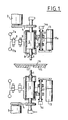
- the drill according to the invention is double-headed.
- Each head comprises a drill 1 with diamond concretion fixed at the end of a spindle 2 which can be driven in rotation by a motor 3 via a belt 4.
- the spindle 2 is rotatably mounted in a body 5 which constitutes the piston of a double-acting cylinder 6. This can be supplied either from a source 7a of high pressure air used during work, or from a source 7b of low pressure air used only during the initialization operation by the 'Intermediate two distributors 8 and 9.
- the body 5 is secured to a finger 10 provided with an electrical sensor 10a. On the path of this finger is a stop consisting of a nut 11 which is prevented from turning and mounted on a screw 12 parallel to the direction of movement of the body 5.
- This screw 12 can be rotated by a gear motor 13 at variable speed and activates an encoder 14s or 14i.
- the two heads are arranged on either side of a table 15 on which a sheet of glass 16 can be placed and which has a hole 17 in the axis of the drills 1.
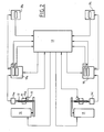
- Each of the encoders 14s and 14i controls a counter with two presets 18s or 18i ( Figure 2) which provides three signals, a positive signal Ws or Wi, a negative signal Vs or Vi and a zero-crossing signal. These counters are located in the control cabinet 19 and are not accessible to the operator. The zero crossing signals are sent to a wheel counter 20s or 20i accessible to the operator.
- the presets Vs and Vi of the counters 18s and 18i allow the Es-Bs and Ei-Bi strokes to be defined.
- the counter 20s makes it possible to display the stroke Es-Cs of the upper head corresponding to two thirds of the thickness to be drilled plus the covering s necessary for unblocking and for the good finishing of the hole.
- the counter 20i makes it possible to display the stroke Ei-Ci of the lower head corresponding to a third of the thickness to be drilled.
- the presets Ws and Wi of the counters 18s and 18i allow the Es-Hs and Ei-Hi strokes to be defined.
- the gear motor 13 drives the nut 11 at a slow working speed, regular and as low as necessary, the counter 18s begins to count down the value Vs.
- the jack brings the finger 10 onto the nut 11 and begins its descent at working speed.
- the force exerted on the drill is perfectly defined by the pressure of the jack.
- the stop 11 actuated by the gear motor 13 takes up the position corresponding to Vs at the start of the cycle.
- the drill 1 If, during a lowering operation, the drill 1 gives a resistant force, due to its wear, which does not allow the programmed working speed to be obtained, the finger 10 will descend less quickly than the nut 11.
- the electric sensor 10a will open giving the signal to change the drill, necessary for its wear.
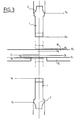
- the upper drill 1 pierces two thirds of the thickness of the plate 16 plus the overlap.
- the lower drill 1 is a third of the thickness.
- the distance Es - Hs is 2/10 th of a millimeter greater than the distance Ei - Hi.
Landscapes
- Engineering & Computer Science (AREA)
- Mechanical Engineering (AREA)
- Drilling And Boring (AREA)
Claims (3)
Applications Claiming Priority (2)
| Application Number | Priority Date | Filing Date | Title |
|---|---|---|---|
| FR8805830A FR2630366A1 (fr) | 1988-04-22 | 1988-04-22 | Machine pour le percage de materiaux durs tels que le verre |
| FR8805830 | 1988-04-22 |
Publications (2)
| Publication Number | Publication Date |
|---|---|
| EP0341114A1 EP0341114A1 (de) | 1989-11-08 |
| EP0341114B1 true EP0341114B1 (de) | 1992-07-08 |
Family
ID=9365872
Family Applications (1)
| Application Number | Title | Priority Date | Filing Date |
|---|---|---|---|
| EP19890401088 Expired - Lifetime EP0341114B1 (de) | 1988-04-22 | 1989-04-19 | Maschine zum Bohren von harten Materialien, wie Glas |
Country Status (3)
| Country | Link |
|---|---|
| EP (1) | EP0341114B1 (de) |
| DE (1) | DE68902008T2 (de) |
| FR (1) | FR2630366A1 (de) |
Families Citing this family (1)
| Publication number | Priority date | Publication date | Assignee | Title |
|---|---|---|---|---|
| GB9202875D0 (en) * | 1992-02-12 | 1992-03-25 | Moore Michael J | Turret mill depth stop assembly |
Family Cites Families (10)
| Publication number | Priority date | Publication date | Assignee | Title |
|---|---|---|---|---|
| US1951093A (en) * | 1932-04-09 | 1934-03-13 | Nat Tube Co | Countersinking machine |
| NL84771C (de) * | 1942-09-29 | |||
| DE840040C (de) * | 1950-10-13 | 1952-05-26 | Schuette Fa Alfred H | Tieflochbohreinrichtung fuer selbsttaetige Drehbaenke |
| US2703994A (en) * | 1952-08-28 | 1955-03-15 | Mezey George | Double drill press |
| GB890635A (en) * | 1960-02-16 | 1962-03-07 | Arthur Scrivener Ltd | Grinding machines |
| GB1299002A (en) * | 1966-11-15 | 1972-12-06 | Kernforschungsanlage Juelich | A drilling machine and a method of operating it |
| FR2050687A5 (de) * | 1969-06-20 | 1971-04-02 | Sirugue Et Cie | |
| DE2119317C2 (de) * | 1971-04-21 | 1982-12-23 | C.F. Scheer & Cie Gmbh & Co, 7000 Stuttgart | Druckmittelbetriebene Bohrvorschubeinheit |
| DE2158886A1 (de) * | 1971-11-27 | 1973-05-30 | Rudolf Staehely Gmbh Maschf | Shifteinrichtung an waelzfraesmaschinen |
| CS171188B2 (de) * | 1972-12-29 | 1976-10-29 |
-
1988
- 1988-04-22 FR FR8805830A patent/FR2630366A1/fr active Pending
-
1989
- 1989-04-19 DE DE1989602008 patent/DE68902008T2/de not_active Expired - Fee Related
- 1989-04-19 EP EP19890401088 patent/EP0341114B1/de not_active Expired - Lifetime
Also Published As
| Publication number | Publication date |
|---|---|
| EP0341114A1 (de) | 1989-11-08 |
| DE68902008D1 (de) | 1992-08-13 |
| FR2630366A1 (fr) | 1989-10-27 |
| DE68902008T2 (de) | 1993-02-04 |
Similar Documents
| Publication | Publication Date | Title |
|---|---|---|
| EP0010043B1 (de) | Umlaufende Vorrichtung zum Zusammendrücken flacher Werkstücke, an einem der Bearbeitungsteile einer Werkzeugmaschine befestigt | |
| FR2533488A1 (fr) | Machine automatique de refendage et de rainurage, notamment pour la fabrication de feuilles en carton ondule | |
| EP0200687B1 (de) | Verfahren zur Steuerung eines automatischen Drehautomaten | |
| FR2751256A1 (fr) | Machine de meulage de verres optiques | |
| EP0341114B1 (de) | Maschine zum Bohren von harten Materialien, wie Glas | |
| CN115301961A (zh) | 一种用于医疗器械加工的长轴加工辅助装置 | |
| FR2638113A1 (fr) | Mandrin d'unite d'usinage pour machines-outils automatiques | |
| EP1522378B1 (de) | Fünfachsige Werkzeugmaschine mit fortlaufender Schleifscheibenabrichtvorrichtung | |
| KR200229032Y1 (ko) | 고속 파이프 절단기 | |
| CA1331909C (fr) | Tour automatique destine a usiner de la matiere en torche | |
| JP2002283185A (ja) | 加工工具の実際の位置データを定める方法及び装置 | |
| CN2765698Y (zh) | 立式钻孔攻丝机 | |
| FI87428C (fi) | Foerfarande och anordning foer tillverkning av borrar | |
| KR100572021B1 (ko) | 타원형상을 갖는 물품의 제조 장치 및 제조 방법 | |
| JP2009248292A (ja) | 非円形穴開け加工装置 | |
| CN101687255B (zh) | 车床 | |
| JP2747530B2 (ja) | 穴加工装置 | |
| CN207971514U (zh) | 花纹式插齿机构 | |
| EP1457851B1 (de) | Digitale Vorrichtung zur Steuerung und Regelung der Translation und Rotation eines Werkzeugs | |
| KR100362527B1 (ko) | 리드스크류 나사산의 정도향상장치 | |
| EP1762319B1 (de) | Verfahren zur Optimierung der Funktion einer Werkzeugmachine mit einer zusätzlichen Stangenführungseinrichtung und entsprechende Werkzeugmaschine | |
| FR2523012A1 (fr) | Dispositif d'usinage de vis a pas variable | |
| JPS5937041A (ja) | レンズ加工機 | |
| JP3009106B1 (ja) | 最適研削圧及び研削スピ−ド調整装置 | |
| KR970005476A (ko) | 내경 나사 가공방법 및 그 장치 |
Legal Events
| Date | Code | Title | Description |
|---|---|---|---|
| PUAI | Public reference made under article 153(3) epc to a published international application that has entered the european phase |
Free format text: ORIGINAL CODE: 0009012 |
|
| AK | Designated contracting states |
Kind code of ref document: A1 Designated state(s): DE GB IT |
|
| 17P | Request for examination filed |
Effective date: 19900406 |
|
| 17Q | First examination report despatched |
Effective date: 19910524 |
|
| GRAA | (expected) grant |
Free format text: ORIGINAL CODE: 0009210 |
|
| AK | Designated contracting states |
Kind code of ref document: B1 Designated state(s): DE GB IT |
|
| GBT | Gb: translation of ep patent filed (gb section 77(6)(a)/1977) | ||
| REF | Corresponds to: |
Ref document number: 68902008 Country of ref document: DE Date of ref document: 19920813 |
|
| ITF | It: translation for a ep patent filed | ||
| PGFP | Annual fee paid to national office [announced via postgrant information from national office to epo] |
Ref country code: GB Payment date: 19930413 Year of fee payment: 5 |
|
| PLBE | No opposition filed within time limit |
Free format text: ORIGINAL CODE: 0009261 |
|
| STAA | Information on the status of an ep patent application or granted ep patent |
Free format text: STATUS: NO OPPOSITION FILED WITHIN TIME LIMIT |
|
| PGFP | Annual fee paid to national office [announced via postgrant information from national office to epo] |
Ref country code: DE Payment date: 19930608 Year of fee payment: 5 |
|
| 26N | No opposition filed | ||
| PG25 | Lapsed in a contracting state [announced via postgrant information from national office to epo] |
Ref country code: GB Effective date: 19940419 |
|
| GBPC | Gb: european patent ceased through non-payment of renewal fee |
Effective date: 19940419 |
|
| PG25 | Lapsed in a contracting state [announced via postgrant information from national office to epo] |
Ref country code: DE Effective date: 19950103 |
|
| PG25 | Lapsed in a contracting state [announced via postgrant information from national office to epo] |
Ref country code: IT Free format text: LAPSE BECAUSE OF NON-PAYMENT OF DUE FEES;WARNING: LAPSES OF ITALIAN PATENTS WITH EFFECTIVE DATE BEFORE 2007 MAY HAVE OCCURRED AT ANY TIME BEFORE 2007. THE CORRECT EFFECTIVE DATE MAY BE DIFFERENT FROM THE ONE RECORDED. Effective date: 20050419 |