EP0341114A1 - Maschine zum Bohren von harten Materialien, wie Glas - Google Patents
Maschine zum Bohren von harten Materialien, wie Glas Download PDFInfo
- Publication number
- EP0341114A1 EP0341114A1 EP89401088A EP89401088A EP0341114A1 EP 0341114 A1 EP0341114 A1 EP 0341114A1 EP 89401088 A EP89401088 A EP 89401088A EP 89401088 A EP89401088 A EP 89401088A EP 0341114 A1 EP0341114 A1 EP 0341114A1
- Authority
- EP
- European Patent Office
- Prior art keywords
- drill
- spindle
- stop
- glass
- machine
- Prior art date
- Legal status (The legal status is an assumption and is not a legal conclusion. Google has not performed a legal analysis and makes no representation as to the accuracy of the status listed.)
- Granted
Links
- 239000011521 glass Substances 0.000 title claims abstract description 10
- 239000000463 material Substances 0.000 title claims abstract description 9
- 229910010293 ceramic material Inorganic materials 0.000 claims abstract description 3
- 239000010438 granite Substances 0.000 claims abstract description 3
- 239000004579 marble Substances 0.000 claims abstract description 3
- 239000011819 refractory material Substances 0.000 claims abstract description 3
- 238000005553 drilling Methods 0.000 claims description 8
- 230000011664 signaling Effects 0.000 claims 1
- 238000010586 diagram Methods 0.000 description 2
- 238000004519 manufacturing process Methods 0.000 description 2
- 241001415961 Gaviidae Species 0.000 description 1
- 230000009172 bursting Effects 0.000 description 1
- 230000001627 detrimental effect Effects 0.000 description 1
- 229910003460 diamond Inorganic materials 0.000 description 1
- 239000010432 diamond Substances 0.000 description 1
- 230000000135 prohibitive effect Effects 0.000 description 1
- 238000011084 recovery Methods 0.000 description 1
- 230000001105 regulatory effect Effects 0.000 description 1
Images


Classifications
-
- B—PERFORMING OPERATIONS; TRANSPORTING
- B23—MACHINE TOOLS; METAL-WORKING NOT OTHERWISE PROVIDED FOR
- B23Q—DETAILS, COMPONENTS, OR ACCESSORIES FOR MACHINE TOOLS, e.g. ARRANGEMENTS FOR COPYING OR CONTROLLING; MACHINE TOOLS IN GENERAL CHARACTERISED BY THE CONSTRUCTION OF PARTICULAR DETAILS OR COMPONENTS; COMBINATIONS OR ASSOCIATIONS OF METAL-WORKING MACHINES, NOT DIRECTED TO A PARTICULAR RESULT
- B23Q5/00—Driving or feeding mechanisms; Control arrangements therefor
- B23Q5/22—Feeding members carrying tools or work
- B23Q5/32—Feeding working-spindles
- B23Q5/323—Feeding working-spindles cam-operated
-
- B—PERFORMING OPERATIONS; TRANSPORTING
- B23—MACHINE TOOLS; METAL-WORKING NOT OTHERWISE PROVIDED FOR
- B23Q—DETAILS, COMPONENTS, OR ACCESSORIES FOR MACHINE TOOLS, e.g. ARRANGEMENTS FOR COPYING OR CONTROLLING; MACHINE TOOLS IN GENERAL CHARACTERISED BY THE CONSTRUCTION OF PARTICULAR DETAILS OR COMPONENTS; COMBINATIONS OR ASSOCIATIONS OF METAL-WORKING MACHINES, NOT DIRECTED TO A PARTICULAR RESULT
- B23Q16/00—Equipment for precise positioning of tool or work into particular locations not otherwise provided for
- B23Q16/001—Stops, cams, or holders therefor
Definitions
- the present invention relates to a machine for drilling hard materials such as glass, marble, granite, refractory materials or ceramic materials, with diamond-tipped drill bits.
- the speed of approach of the drill must be the fastest possible to reduce the duration of a drilling cycle, but on the other hand its speed of advance during work must be very slow, regular, adjustable and faithful .
- the bearing force exerted by the drill must be conveniently adjustable to avoid breaking of thin products or bursting at the time of knockout.
- the advance speed of the drill must moreover be compatible over time with its state of wear. An advance which has become relatively too rapid inevitably leads to the breaking of the glass.
- variable advance systems with adjustable stroke are commonly produced from digital controls directly ensuring the advance of the tool.
- these systems have serious drawbacks in the case of drills with a hardened concretion. Indeed, the possible difference between fast and slow speeds is limited, which makes it necessary to reduce the approach speed.
- the cost of these systems is prohibitive in the case of a multi-hole drill; thus a double head drill to drill eight holes has sixteen spindles which requires the use of four four-axis digital controls. In the case of a lack of biting of the drill, it continues to advance, which leads to a rupture of the material during drilling.
- the present invention relates to a drill which overcomes these drawbacks.
- the drill according to the invention comprises means for axially moving the spindle of the drill, an adjustable stop to limit the stroke of the spindle, and means for moving this stop and is characterized in that the means for axially moving the spindle of the drill consist of a double-acting cylinder and in that it comprises an initialization device comprising a switch actuated by the relative movement of the stop and the spindle due to the meeting of the drill with the material to be drilled. The difference between the speeds of the two movements can be as large as necessary.
- the pushing force on the drill is constant and conveniently adjustable; the movement of advance of the drill is moreover self-regulated because, in the event of lack of bite of the drill, the stop advances faster than the spindle, which actuates the switch and thus signals the wear of the drill. It is possible to provide a rotary or linear encoder linked to the advance of the stop to program, after initialization, the different strokes using up-down counters.
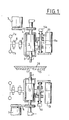
- the drill according to the invention is preferably double-headed.
- each head comprises a drill 1 with diamond concretion fixed to the end of a spindle 2 which can be driven in rotation by a motor 3 by means of a belt 4.
- the spindle 2 is rotatably mounted in a body 5 which constitutes the piston of a double-acting cylinder 6. This can be supplied either from a source 7 a of high pressure air used during work, or from a source 7 b of low pressure air used only during the initialization operation via two distributors 8 and 9.
- the body 5 is integral with a finger 10 provided with an electrical sensor 10 a . On the path of this finger is a stop consisting of a nut 11 which is prevented from turning and mounted on a screw 12 parallel to the direction of movement of the body 5.
- This screw 12 can be rotated by a gear motor 13 at variable speed and operates a 14 s or 14 i encoder.
- the two heads are arranged on either side of a table 15 on which a sheet of glass 16 can be placed and which has a hole 17 in the axis of the drills 1.
- Each of the encoders 14 s and 14 i controls a counter with two presets 18 s or 18 i ( Figure 2) which provides three signals, a positive signal Ws or Wi, a negative signal Vs or Vi and a zero-crossing signal. These counters are located in the control cabinet 19 and are not accessible to the operator. The zero crossing signals are sent to a wheel counter 20 s or 20 i accessible to the operator.
- Fs The position of the upper spindle nose 2 retracted. It is constant.
- Fi The corresponding position of the lower pin 2.
- Ai The corresponding position of the end of the lower drill 1. It is variable (like As).
- Es The position corresponding to the upper face of the product. It is variable with this thickness.
- Ei The position corresponding to the underside of the product. It is constant, it corresponds to the level of the support table.
- Bs The upper point or drill 1 must change from fast approach speed to slow working speed. It is located at a fixed distance of Es from 2 to 3/10 th of a mm for example.
- the distance Bs-Es compensates for the manufacturing tolerances on the thickness of the glass and prevents the drill from striking the product at high speed of approach.
- Bi The corresponding point for lower drill 1.
- Cs The position of the end of the upper drill 1 at the end of the drilling.
- Ci The position of the end of the lower drill 1 at the end of the drilling.
- Hs A point located at a given distance from Es on the order of 0.8 to 1mm for 3.2mm glass.
- Hi A point located at a distance from Ei such that the distance Es Hs is approximately 2 / 10mm greater than the distance Ei Hi.
- the points Hs and Hi will serve as a reference to avoid the meeting of the two drills.
- the presets Vs and Vi of the counters 18s and 18i allow the Es-Bs and Ei-Bi strokes to be defined.
- the counter 20s makes it possible to display the stroke Es-Cs of the upper head corresponding to two thirds of the thickness to be drilled plus the overlap ⁇ necessary for unblocking and for the good finish of the hole.
- the 20i counter allows display the stroke Ei-Ci of the lower head corresponding to one third of the thickness to be drilled.
- the presets Ws and Wi of the counters 18s and 18i allow the Es-Hs and Ei-Hi strokes to be defined.
- the step of the lower head is identical.
- the upper head is in the high position thanks to its pneumatic cylinder 6.
- It causes the nut 11 with the gear motor 13 in the high position, in contact with the finger 10.
- the electrical sensor 10 a is contacted.
- the upper head is lowered by putting the compressed air from the low pressure circuit 7b on the cylinder 6.
- the nut 11 is lowered simultaneously at low speed thanks to the geared motor 13.
- the finger remains in contact with the nut.
- the electrical sensor 10 has remained contacted.
- the drill reaches the surface of the product, the low pressure exerted due to the air and the low attack speed prevent it from breaking, the nut continues its downward movement actuated by the gear motor 13.
- the sensor 10a is no longer contacted. It then initializes the zero of the up-down counter 18s. - Valve 9 reverses the air inlets on the cylinder. - The jack 6 raises the head. - The gear motor 13 raises the nut. - The 18s counter counts down to the numbering corresponding to Vs. - The gear motor 13 stops, the nut 11 is then on standby in the position corresponding to the position Bs of the drill 1.
- the beginning of the cycle puts the cylinder in rapid descent by the high pressure circuit 7 a .
- the gear motor 13 drives the nut 11 at slow working speed, regular and as low as necessary, the counter 18 s begins to count down the value Vs.
- the jack brings the finger 10 onto the nut 11 and begins its descent at working speed.
- the force exerted on the drill is perfectly defined by the pressure of the jack.
- the drill 1 If, during a lowering operation, the drill 1 gives a resistant force, due to its wear, which does not make it possible to obtain the programmed working speed, the must 10 will descend less quickly than the nut 11.
- the electric sensor 10 a will open giving the signal to change the drill, necessary for its wear.
- the upper drill 1 pierces two thirds of the thickness of the plate 16 plus the overlap.
- the lower drill 1 is a third of the thickness.
- the distance Es - Hs is 2/10 th of a millimeter greater than the distance Ei - Hi.
Landscapes
- Engineering & Computer Science (AREA)
- Mechanical Engineering (AREA)
- Drilling And Boring (AREA)
Applications Claiming Priority (2)
| Application Number | Priority Date | Filing Date | Title |
|---|---|---|---|
| FR8805830A FR2630366A1 (fr) | 1988-04-22 | 1988-04-22 | Machine pour le percage de materiaux durs tels que le verre |
| FR8805830 | 1988-04-22 |
Publications (2)
| Publication Number | Publication Date |
|---|---|
| EP0341114A1 true EP0341114A1 (de) | 1989-11-08 |
| EP0341114B1 EP0341114B1 (de) | 1992-07-08 |
Family
ID=9365872
Family Applications (1)
| Application Number | Title | Priority Date | Filing Date |
|---|---|---|---|
| EP19890401088 Expired - Lifetime EP0341114B1 (de) | 1988-04-22 | 1989-04-19 | Maschine zum Bohren von harten Materialien, wie Glas |
Country Status (3)
| Country | Link |
|---|---|
| EP (1) | EP0341114B1 (de) |
| DE (1) | DE68902008T2 (de) |
| FR (1) | FR2630366A1 (de) |
Cited By (1)
| Publication number | Priority date | Publication date | Assignee | Title |
|---|---|---|---|---|
| EP0556048A1 (de) * | 1992-02-12 | 1993-08-18 | Michael James Moore | Tiefeanschlag für eine Werkzeugmaschine |
Citations (11)
| Publication number | Priority date | Publication date | Assignee | Title |
|---|---|---|---|---|
| US1951093A (en) * | 1932-04-09 | 1934-03-13 | Nat Tube Co | Countersinking machine |
| US2391398A (en) * | 1942-09-29 | 1945-12-25 | Vlieg Charles B De | Horizontal boring machine |
| DE840040C (de) * | 1950-10-13 | 1952-05-26 | Schuette Fa Alfred H | Tieflochbohreinrichtung fuer selbsttaetige Drehbaenke |
| US2703994A (en) * | 1952-08-28 | 1955-03-15 | Mezey George | Double drill press |
| GB890635A (en) * | 1960-02-16 | 1962-03-07 | Arthur Scrivener Ltd | Grinding machines |
| FR2050687A5 (de) * | 1969-06-20 | 1971-04-02 | Sirugue Et Cie | |
| DE2014313A1 (de) * | 1970-03-25 | 1971-09-30 | Gebr. Heller Maschinenfabrik GmbH, 7440 Nürtingen | Vorschubsystem für Werkzeugmaschinen |
| DE2119317A1 (de) * | 1971-04-21 | 1972-10-26 | CF. Scheer & Cie, 7000 Stuttgart-Feuerbach | Bohrvorrichtung, insbesondere zur Holzbearbeitung |
| GB1299002A (en) * | 1966-11-15 | 1972-12-06 | Kernforschungsanlage Juelich | A drilling machine and a method of operating it |
| DE2158886A1 (de) * | 1971-11-27 | 1973-05-30 | Rudolf Staehely Gmbh Maschf | Shifteinrichtung an waelzfraesmaschinen |
| FR2212202A1 (de) * | 1972-12-29 | 1974-07-26 | Siemens Ag |
-
1988
- 1988-04-22 FR FR8805830A patent/FR2630366A1/fr active Pending
-
1989
- 1989-04-19 DE DE1989602008 patent/DE68902008T2/de not_active Expired - Fee Related
- 1989-04-19 EP EP19890401088 patent/EP0341114B1/de not_active Expired - Lifetime
Patent Citations (11)
| Publication number | Priority date | Publication date | Assignee | Title |
|---|---|---|---|---|
| US1951093A (en) * | 1932-04-09 | 1934-03-13 | Nat Tube Co | Countersinking machine |
| US2391398A (en) * | 1942-09-29 | 1945-12-25 | Vlieg Charles B De | Horizontal boring machine |
| DE840040C (de) * | 1950-10-13 | 1952-05-26 | Schuette Fa Alfred H | Tieflochbohreinrichtung fuer selbsttaetige Drehbaenke |
| US2703994A (en) * | 1952-08-28 | 1955-03-15 | Mezey George | Double drill press |
| GB890635A (en) * | 1960-02-16 | 1962-03-07 | Arthur Scrivener Ltd | Grinding machines |
| GB1299002A (en) * | 1966-11-15 | 1972-12-06 | Kernforschungsanlage Juelich | A drilling machine and a method of operating it |
| FR2050687A5 (de) * | 1969-06-20 | 1971-04-02 | Sirugue Et Cie | |
| DE2014313A1 (de) * | 1970-03-25 | 1971-09-30 | Gebr. Heller Maschinenfabrik GmbH, 7440 Nürtingen | Vorschubsystem für Werkzeugmaschinen |
| DE2119317A1 (de) * | 1971-04-21 | 1972-10-26 | CF. Scheer & Cie, 7000 Stuttgart-Feuerbach | Bohrvorrichtung, insbesondere zur Holzbearbeitung |
| DE2158886A1 (de) * | 1971-11-27 | 1973-05-30 | Rudolf Staehely Gmbh Maschf | Shifteinrichtung an waelzfraesmaschinen |
| FR2212202A1 (de) * | 1972-12-29 | 1974-07-26 | Siemens Ag |
Cited By (1)
| Publication number | Priority date | Publication date | Assignee | Title |
|---|---|---|---|---|
| EP0556048A1 (de) * | 1992-02-12 | 1993-08-18 | Michael James Moore | Tiefeanschlag für eine Werkzeugmaschine |
Also Published As
| Publication number | Publication date |
|---|---|
| DE68902008T2 (de) | 1993-02-04 |
| DE68902008D1 (de) | 1992-08-13 |
| FR2630366A1 (fr) | 1989-10-27 |
| EP0341114B1 (de) | 1992-07-08 |
Similar Documents
| Publication | Publication Date | Title |
|---|---|---|
| EP1080012B1 (de) | Vorrichtung zum anbringen von hülsen auf vorbeilaufenden gegenständen | |
| JP2002273655A (ja) | 加工工具の実際の位置を定める方法及びそのための装置 | |
| EP0200687B1 (de) | Verfahren zur Steuerung eines automatischen Drehautomaten | |
| FR2533488A1 (fr) | Machine automatique de refendage et de rainurage, notamment pour la fabrication de feuilles en carton ondule | |
| EP0341114B1 (de) | Maschine zum Bohren von harten Materialien, wie Glas | |
| FR2638113A1 (fr) | Mandrin d'unite d'usinage pour machines-outils automatiques | |
| EP1522378B1 (de) | Fünfachsige Werkzeugmaschine mit fortlaufender Schleifscheibenabrichtvorrichtung | |
| JP2002283185A (ja) | 加工工具の実際の位置データを定める方法及び装置 | |
| CA1331909C (fr) | Tour automatique destine a usiner de la matiere en torche | |
| CN2765698Y (zh) | 立式钻孔攻丝机 | |
| CN108747373A (zh) | 一种全自动数控倒角机 | |
| JP2747530B2 (ja) | 穴加工装置 | |
| EP0342153B1 (de) | Zusatzvorrichtung zum präzisen Drehen eines Werkstücks | |
| JP2654888B2 (ja) | シヤリング機における切断刃の送り装置 | |
| EP0015850A1 (de) | Transportvorrichtung für kleine Stücke | |
| KR970005476A (ko) | 내경 나사 가공방법 및 그 장치 | |
| JP3009106B1 (ja) | 最適研削圧及び研削スピ−ド調整装置 | |
| JPH05277831A (ja) | ねじ切り装置 | |
| JPS643660Y2 (de) | ||
| JPH023370Y2 (de) | ||
| FR2523012A1 (fr) | Dispositif d'usinage de vis a pas variable | |
| JP2004160586A (ja) | 部品加工装置及び方法 | |
| JPH039997Y2 (de) | ||
| JPS5937041A (ja) | レンズ加工機 | |
| EP1762319B1 (de) | Verfahren zur Optimierung der Funktion einer Werkzeugmachine mit einer zusätzlichen Stangenführungseinrichtung und entsprechende Werkzeugmaschine |
Legal Events
| Date | Code | Title | Description |
|---|---|---|---|
| PUAI | Public reference made under article 153(3) epc to a published international application that has entered the european phase |
Free format text: ORIGINAL CODE: 0009012 |
|
| AK | Designated contracting states |
Kind code of ref document: A1 Designated state(s): DE GB IT |
|
| 17P | Request for examination filed |
Effective date: 19900406 |
|
| 17Q | First examination report despatched |
Effective date: 19910524 |
|
| GRAA | (expected) grant |
Free format text: ORIGINAL CODE: 0009210 |
|
| AK | Designated contracting states |
Kind code of ref document: B1 Designated state(s): DE GB IT |
|
| GBT | Gb: translation of ep patent filed (gb section 77(6)(a)/1977) | ||
| REF | Corresponds to: |
Ref document number: 68902008 Country of ref document: DE Date of ref document: 19920813 |
|
| ITF | It: translation for a ep patent filed | ||
| PGFP | Annual fee paid to national office [announced via postgrant information from national office to epo] |
Ref country code: GB Payment date: 19930413 Year of fee payment: 5 |
|
| PLBE | No opposition filed within time limit |
Free format text: ORIGINAL CODE: 0009261 |
|
| STAA | Information on the status of an ep patent application or granted ep patent |
Free format text: STATUS: NO OPPOSITION FILED WITHIN TIME LIMIT |
|
| PGFP | Annual fee paid to national office [announced via postgrant information from national office to epo] |
Ref country code: DE Payment date: 19930608 Year of fee payment: 5 |
|
| 26N | No opposition filed | ||
| PG25 | Lapsed in a contracting state [announced via postgrant information from national office to epo] |
Ref country code: GB Effective date: 19940419 |
|
| GBPC | Gb: european patent ceased through non-payment of renewal fee |
Effective date: 19940419 |
|
| PG25 | Lapsed in a contracting state [announced via postgrant information from national office to epo] |
Ref country code: DE Effective date: 19950103 |
|
| PG25 | Lapsed in a contracting state [announced via postgrant information from national office to epo] |
Ref country code: IT Free format text: LAPSE BECAUSE OF NON-PAYMENT OF DUE FEES;WARNING: LAPSES OF ITALIAN PATENTS WITH EFFECTIVE DATE BEFORE 2007 MAY HAVE OCCURRED AT ANY TIME BEFORE 2007. THE CORRECT EFFECTIVE DATE MAY BE DIFFERENT FROM THE ONE RECORDED. Effective date: 20050419 |