EP0340481B1 - Arrangement pour dépouiller les signaux d'un capteur incrémenteil - Google Patents
Arrangement pour dépouiller les signaux d'un capteur incrémenteil Download PDFInfo
- Publication number
- EP0340481B1 EP0340481B1 EP89106295A EP89106295A EP0340481B1 EP 0340481 B1 EP0340481 B1 EP 0340481B1 EP 89106295 A EP89106295 A EP 89106295A EP 89106295 A EP89106295 A EP 89106295A EP 0340481 B1 EP0340481 B1 EP 0340481B1
- Authority
- EP
- European Patent Office
- Prior art keywords
- signal
- signals
- speed
- angular
- counter
- Prior art date
- Legal status (The legal status is an assumption and is not a legal conclusion. Google has not performed a legal analysis and makes no representation as to the accuracy of the status listed.)
- Expired - Lifetime
Links
Images


Classifications
-
- G—PHYSICS
- G01—MEASURING; TESTING
- G01D—MEASURING NOT SPECIALLY ADAPTED FOR A SPECIFIC VARIABLE; ARRANGEMENTS FOR MEASURING TWO OR MORE VARIABLES NOT COVERED IN A SINGLE OTHER SUBCLASS; TARIFF METERING APPARATUS; MEASURING OR TESTING NOT OTHERWISE PROVIDED FOR
- G01D5/00—Mechanical means for transferring the output of a sensing member; Means for converting the output of a sensing member to another variable where the form or nature of the sensing member does not constrain the means for converting; Transducers not specially adapted for a specific variable
- G01D5/12—Mechanical means for transferring the output of a sensing member; Means for converting the output of a sensing member to another variable where the form or nature of the sensing member does not constrain the means for converting; Transducers not specially adapted for a specific variable using electric or magnetic means
- G01D5/244—Mechanical means for transferring the output of a sensing member; Means for converting the output of a sensing member to another variable where the form or nature of the sensing member does not constrain the means for converting; Transducers not specially adapted for a specific variable using electric or magnetic means influencing characteristics of pulses or pulse trains; generating pulses or pulse trains
- G01D5/24404—Interpolation using high frequency signals
-
- G—PHYSICS
- G01—MEASURING; TESTING
- G01D—MEASURING NOT SPECIALLY ADAPTED FOR A SPECIFIC VARIABLE; ARRANGEMENTS FOR MEASURING TWO OR MORE VARIABLES NOT COVERED IN A SINGLE OTHER SUBCLASS; TARIFF METERING APPARATUS; MEASURING OR TESTING NOT OTHERWISE PROVIDED FOR
- G01D5/00—Mechanical means for transferring the output of a sensing member; Means for converting the output of a sensing member to another variable where the form or nature of the sensing member does not constrain the means for converting; Transducers not specially adapted for a specific variable
- G01D5/12—Mechanical means for transferring the output of a sensing member; Means for converting the output of a sensing member to another variable where the form or nature of the sensing member does not constrain the means for converting; Transducers not specially adapted for a specific variable using electric or magnetic means
- G01D5/244—Mechanical means for transferring the output of a sensing member; Means for converting the output of a sensing member to another variable where the form or nature of the sensing member does not constrain the means for converting; Transducers not specially adapted for a specific variable using electric or magnetic means influencing characteristics of pulses or pulse trains; generating pulses or pulse trains
- G01D5/245—Mechanical means for transferring the output of a sensing member; Means for converting the output of a sensing member to another variable where the form or nature of the sensing member does not constrain the means for converting; Transducers not specially adapted for a specific variable using electric or magnetic means influencing characteristics of pulses or pulse trains; generating pulses or pulse trains using a variable number of pulses in a train
- G01D5/2454—Encoders incorporating incremental and absolute signals
- G01D5/2455—Encoders incorporating incremental and absolute signals with incremental and absolute tracks on the same encoder
- G01D5/2457—Incremental encoders having reference marks
Definitions
- the invention relates to an arrangement for evaluating signals from an incremental encoder, in particular in the case of a printing press, at least two tachometer signals being phase-shifted relative to one another, which are counted when there is a permissible combination of the tachometer signals.
- an incremental encoder In order to determine the position of a machine part, in particular the rotational position of a rotating machine part, and to use it for control purposes, it is known to use an incremental encoder to generate two tacho signals that are phase-shifted with respect to one another and to count their individual pulses.
- errors can occur if interference signals are superimposed on the speedometer signals. These impulses can arise, for example, from interference in connection lines between the incremental encoder and a control unit.
- a cause of interference pulses can also lie in the incremental encoder itself, for example if opaque particles penetrate an optical incremental encoder.
- a circuit arrangement for the digital processing of multi-phase pulse trains of a pulse generator is already known (DE 36 36 000 A1), in which a pulse converter is provided in front of an up-down counter, in which an omission of individual pulses or a displacement of pulse edges of the pulse train takes place. This serves to divide the frequency of the pulses derived from the pulse generator in order to obtain a desired scale for displaying the movement of a machine. Protection against disturbed impulses is not associated with this.
- Circuit arrangements are also known (DE 33 18 351 C2, DE 32 19 894 C2), in which special precautions are taken to detect the direction of rotation and to prevent uncertainties in the area of a reversal of direction.
- special measures to protect against interference pulses are not available here either.
- DAS 2 207 224 an error-protected incremental position measuring system in which more than two, in particular four, probes, two counters and a comparator for the two counter readings are provided in the incremental encoder.
- DAS 2 207 224 an error-protected incremental position measuring system in which more than two, in particular four, probes, two counters and a comparator for the two counter readings are provided in the incremental encoder.
- the object of the invention is to enable a correct evaluation of signals from an incremental encoder, even if they are disturbed.
- the arrangement according to the invention is characterized in that a switching network is connected upstream of a counter, that the tacho signals can be fed to the switching network, and that outputs of the counter are connected to inputs of the switching network.
- a signal for controlling the counting direction is generated by comparing one of the tachometer signals with the second least significant digit of the counter reading, and that an enable signal, which enables counting of the tachometer signals, by comparing two tachometer signals and then comparing them with the least significant digit of the meter reading is generated.
- a further increase in interference immunity is achieved according to another development of the invention in that a direction signal derived independently of the tachometer signals is linked to signals derived from the tachometer signals for controlling the counting direction, and in that the signal obtained by the linkage is linked to a release signal derived from the tachometer signals is linked to form a further release signal.
- a speed signal is derived which changes from a first to a second logic state at a predetermined speed of the incremental encoder, and in that the speed signal with the signal for controlling the counting direction and the direction signal is linked in such a way that the tachometer signals are counted continuously at lower speeds.
- This arrangement is characterized on the one hand by a low outlay, on the other hand the computer is relieved of the current counting of the pulses when using a counter upstream of a computer.
- further inputs of the switching network can be supplied with a direction signal and a speed signal, which changes from a first to a second logic state at a predetermined speed of the incremental encoder. A further check of the tachometer signals is thus made possible in a simple manner.
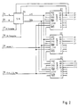
- an incremental encoder 1 known per se is provided.
- Such incremental encoders consist, for example, of a partial disk provided with optical markings, which is scanned by opto-electrical converters.
- One of the opto-electrical converters emits a pulse 0 during one revolution.
- tachometer signals A and B are generated, which are meandering and out of phase with one another by 90 °.
- the tachometer signals A and B each comprise 1024 pulses per revolution.
- the tachometer signals O, A and B are fed to the inputs of a switch 2, the other inputs of which are supplied with electronically generated test signals Test-0, Test-A and Test-B.
- the changeover switch can be controlled by the computer 3, so that the circuits described below can also be tested in a test mode when the machine is at a standstill.
- the tachometer signals A and B are evaluated to record the direction of rotation and the position as well as to measure the speed or speed. To detect the direction of rotation, the tachometer signals A and B are fed to a circuit 4.
- the circuit 4 has two outputs 5, 6, a signal to identify the direction of rotation being present at the output 5 and a pulse being emitted at the output 6 when the direction of rotation changes. While the signal indicating the direction of rotation is fed to a data input of the computer, the pulse at output 6 generates a program interruption (interrupt, IR).
- the speed is measured with two counters 8, 9, to which one of the tachometer signals A and B is fed via a changeover switch 7 and a frequency divider 17.
- the switch 7 is controlled by a circuit 18 such that if one of the tachometer signals fails, the other is forwarded.
- the frequency divider 17 is programmable, for which purpose the respective divider ratio is supplied from the computer 3 via the data bus 10.
- a counter signal is fed to the counters 8, 9, the frequency of which, according to the resolution of the speed measurement, is significantly higher than the frequency of the tachometer signals.
- the frequency of the reference signal can be varied. For this purpose, a corresponding value is fed to the oscillator 11 for the reference signal via the bus system 10.
- the speed is now measured in such a way that one of the counters alternately counts the pulses of the reference signal between two pulses emitted by the frequency divider 17.
- a program interruption IR
- the computer reads the counter reading via the data bus 10.
- the other counter has already been started, so that the duration of each period of the output signals of the frequency divider 17 is measured.
- the measured values are converted into speed values in computer 3.
- the tachometer signals A and B and the pulse 0 are fed to a counter circuit 12. It is also provided that pulse 0 triggers a program interruption.
- the counter circuit is reset by pulse 0, so that the counter reading indicates the position or the angle of rotation in relation to an initial position.
- this value is fed as an actual position to a comparator 13 and compared there with a target position which was previously written into a register 14 by the computer. If the machine has reached the target position, both values are the same and the comparator 13 triggers a program interruption, whereupon the computer initiates the measures provided for at the target position. Immediately afterwards, a new target position can be entered via register 14 can be entered. Until the machine reaches this new target position, it is not necessary to continuously record the position of the machine in the computer.
- additional pulses can be supplied to the counter circuit from an additional pulse generator 15, the frequency of which corresponds to a multiple of the frequency of the tachometer signals.
- the oscillator 15 is controlled by the computer 3 based on the frequency measurement using the circuits 7 to 11.
- the counting of the additional pulses gives the least significant digits of the actual position supplied to the comparator 13. Due to the inertia of the machine, the frequency of the tachometer signals does not change too quickly, so that the frequency measurement and thus the control of the oscillator 15 for the subsequent periods of the tachometer signal take place with sufficient accuracy.
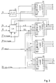
- FIG. 2 shows an exemplary embodiment for the counter circuit 12 (FIG. 1), in which three 4-bit counters of the type LS 669 are provided. Carry outputs of counters 21 and 22 are connected to inputs of counters 22 and 23, so that there is a total of a 12-bit counter.
- the tachometer signals A and B are fed via inputs 24, 25 to a switching network 26, where an up / down signal U / by means of a logical combination with the two least significant digits Q1 and Q2 of the counter reading.
- D and a counter enable signal ENA be derived.
- the signals DR specification and DR enable are fed to the switching network 26 via inputs 27, 28.
- the DR default signal indicates the direction of rotation of the machine.
- the DR enable signal indicates whether the speed of the machine is above or below a speed at which a change in direction can take place.
- Another input 29 is provided for pulse 0, which controls the LOAD input and thus resets the counters, since the data inputs A to D are at ground potential.
- the counter circuit 12 has an input 30 for a clock signal CLK.
- the resolution when determining the position can be increased by generating 15 additional pulses with the help of an oscillator, the frequency of which is a multiple of the frequency of the clock signals.
- the oscillator 15 generates pulses with 64 times the tacho frequency, which are fed to a further counter 31 of the type LS 669.
- the counting direction of the further counter 31 is controlled by the DR preset signal. This increases the counter reading to 16 digits (Q1 'to Q4', Q1 to Q12) and increases the resolution to 16 times, since a fourfold counting frequency is already achieved by evaluating both edges of the tachometer signals A and B.
- the switching network comprises an antivalence circuit 41 and two equivalence circuits 42, 43.
- the tachometer signals A, B are fed via inputs 24, 25 to both inputs of the antivalence circuit 41.
- the output of the antivalence circuit 41 is connected to an input of the equivalence circuit 43, at the other input of which the least significant bit (LSB) Q1 is present.
- the release signal can be output 44 ENA for the counter.
- To obtain an up / down signal U / D the tacho signal A and the second least significant digit Q2 of the counter reading are fed to the equivalence circuit 42, at the output 45 of which the signal U / D can be removed.
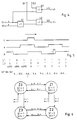
- FIG. 5 shows time diagrams of the signals O, A and B for a predetermined direction of rotation, for example for clockwise rotation.
- values of Q1 and Q2 of the counter 21 and the total count Q1 to Q12 are indicated in FIG.
- the counter reading Q1 'to Q4' (Fig. 3) is indicated.
- the signal O occurs once during each revolution, while the tachometer signals A and B occur more frequently according to the division of the incremental encoder - for example 1024 times per revolution.
- the tachometer signals A and B are 90 ° out of phase with each other.
- the counter is reset by pulse 0, so that the counter reading becomes 0 and the two least significant digits Q1 and Q2 also assume the value 0.
- a and B become different sizes, so that the value 1 is at the output of the antivalence circuit 41.
- U / D 1, which causes the counter to increment (count up).
- the switching network 26 including the two least significant digits of the counter 21, can then assume the states Z0, Z1, Z2 and Z3.
- the values present at the outputs Q1 and Q2 in these states are specified in the circles representing the states.
- a transition from one state to another can only take place in the sense of counting up or down, which is indicated in FIG. 6 by arrows between the circles.
- the filtering effect of the switching network is explained using the example of an interference pulse 46 (FIG. 5).
- the switching network shown in FIG. 4 thus has the effect that only the respectively neighboring states are permitted in any state. Counter reading 0 can therefore only be followed by counter reading 1 or 4095.
- Another Increasing operational reliability is achieved by specifying the direction of rotation via the computer 3 (FIG. 1). A change in the direction of rotation indicated by the tachometer signals A and B is recognized as an error if this contradicts the signal DR specification supplied by the computer. However, this additional check can lead to errors at standstill or at low speeds and is therefore switched off if a change of direction is possible due to low speeds. A further DR release signal is therefore supplied by the computer, which assumes the value 1 above a predetermined speed.
- the switching network according to FIG. 7 contains an antivalence circuit 50, an AND circuit 51 and an OR circuit 52.
- this counter can only be blocked if the value 1 is supplied to both inputs of the AND circuit 51. This is the case when both the DR enable signal has the value 1 and the two signals U / which are obtained independently of one another and which characterize the direction of rotation. D and DR specification are different from each other.
Landscapes
- Physics & Mathematics (AREA)
- General Physics & Mathematics (AREA)
- Transmission And Conversion Of Sensor Element Output (AREA)
- Indicating Or Recording The Presence, Absence, Or Direction Of Movement (AREA)
- Optical Transform (AREA)
- Inking, Control Or Cleaning Of Printing Machines (AREA)
Claims (8)
Applications Claiming Priority (2)
| Application Number | Priority Date | Filing Date | Title |
|---|---|---|---|
| DE3815533A DE3815533C1 (fr) | 1988-05-06 | 1988-05-06 | |
| DE3815533 | 1988-05-06 |
Publications (2)
| Publication Number | Publication Date |
|---|---|
| EP0340481A1 EP0340481A1 (fr) | 1989-11-08 |
| EP0340481B1 true EP0340481B1 (fr) | 1992-03-04 |
Family
ID=6353835
Family Applications (1)
| Application Number | Title | Priority Date | Filing Date |
|---|---|---|---|
| EP89106295A Expired - Lifetime EP0340481B1 (fr) | 1988-05-06 | 1989-04-10 | Arrangement pour dépouiller les signaux d'un capteur incrémenteil |
Country Status (6)
| Country | Link |
|---|---|
| US (1) | US4982413A (fr) |
| EP (1) | EP0340481B1 (fr) |
| JP (1) | JPH0217415A (fr) |
| AU (1) | AU619825B2 (fr) |
| CA (1) | CA1308775C (fr) |
| DE (2) | DE3815533C1 (fr) |
Cited By (1)
| Publication number | Priority date | Publication date | Assignee | Title |
|---|---|---|---|---|
| DE102005006694A1 (de) * | 2005-02-15 | 2006-08-24 | Conti Temic Microelectronic Gmbh | Verfahren und Vorrichtung zur Bestimmung der Position eines Verstellantriebs |
Families Citing this family (8)
| Publication number | Priority date | Publication date | Assignee | Title |
|---|---|---|---|---|
| DE3815530A1 (de) * | 1988-05-06 | 1989-11-16 | Heidelberger Druckmasch Ag | Verfahren zur ermittlung der drehzahl einer maschine |
| DE3815534A1 (de) * | 1988-05-06 | 1989-11-16 | Heidelberger Druckmasch Ag | System zur erfassung der position von beweglichen maschinenteilen |
| JP2697919B2 (ja) * | 1989-09-29 | 1998-01-19 | キヤノン株式会社 | 信号内挿回路及び該回路を備えた変位測定装置 |
| JP2714651B2 (ja) * | 1990-06-29 | 1998-02-16 | 富士通株式会社 | カウンタ回路 |
| DE4137979B4 (de) * | 1991-11-19 | 2004-05-06 | Heidelberger Druckmaschinen Ag | Antrieb für eine Druckmaschine mit mindestens zwei mechanisch voneinander entkoppelten Druckwerken |
| DE4321179A1 (de) * | 1993-06-25 | 1995-01-05 | Heidelberger Druckmasch Ag | Verfahren und Einrichtung zur Steuerung oder Regelung von Betriebsvorgängen einer drucktechnischen Maschine |
| CN100340416C (zh) * | 2004-01-30 | 2007-10-03 | 明基电通股份有限公司 | 校正装置与方法和具有校正装置的喷墨打印机 |
| DE102006048851A1 (de) | 2006-10-16 | 2008-04-17 | Siemens Ag | Vorrichtung und Verfahren zur Erfassung einer Position einer Antriebseinheit |
Citations (5)
| Publication number | Priority date | Publication date | Assignee | Title |
|---|---|---|---|---|
| DE2207224A1 (fr) * | 1972-02-16 | 1973-08-23 | ||
| DE3219894C2 (de) * | 1982-05-27 | 1984-08-30 | Danfoss A/S, Nordborg | Inkremental-Digital-Umsetzer |
| DE3318351C2 (de) * | 1983-05-20 | 1986-05-22 | Preh, Elektrofeinmechanische Werke Jakob Preh Nachf. Gmbh & Co, 8740 Bad Neustadt | Schaltungsanordnung für eine drehzahl- und drehrichtungsabhängige Auswerteschaltung eines inkrementalen Drehrichtungsimpulsgebers |
| DE3636000A1 (de) * | 1985-11-07 | 1987-05-14 | Simmering Graz Pauker Ag | Schaltungsanordnung zur digitalen verarbeitung mehrphasiger impulsfolgen eines impulsgebers |
| DE2930793C2 (fr) * | 1979-07-28 | 1988-03-31 | Licentia Patent-Verwaltungs-Gmbh, 6000 Frankfurt, De |
Family Cites Families (11)
| Publication number | Priority date | Publication date | Assignee | Title |
|---|---|---|---|---|
| US3740532A (en) * | 1971-05-25 | 1973-06-19 | Kureha Chemical Ind Co Ltd | Digital counter averaging system |
| FR2153526A5 (fr) * | 1971-09-14 | 1973-05-04 | Charbonnages De France | |
| DE2352975A1 (de) * | 1973-10-23 | 1975-04-30 | Teldix Gmbh | Verfahren zur messung der groesse und richtung der relativbewegung eines sich bewegenden teiles |
| US4475086A (en) * | 1982-03-31 | 1984-10-02 | Eastman Kodak Company | Duty cycle detector |
| JPS60107521A (ja) * | 1983-11-16 | 1985-06-13 | Sumitomo Electric Ind Ltd | 回転センサ |
| US4715051A (en) * | 1985-04-12 | 1987-12-22 | Giardina Joseph J | Electronic potentiometer |
| JPS62285009A (ja) * | 1986-06-03 | 1987-12-10 | Nec Corp | 位置検出装置 |
| JPS6347612A (ja) * | 1986-08-13 | 1988-02-29 | Mitsutoyo Corp | 変位検出装置 |
| US4844610A (en) * | 1988-04-29 | 1989-07-04 | Becton, Dickinson And Company | Backflow isolator and capture system |
| DE3815534A1 (de) * | 1988-05-06 | 1989-11-16 | Heidelberger Druckmasch Ag | System zur erfassung der position von beweglichen maschinenteilen |
| DE3815535A1 (de) * | 1988-05-06 | 1989-11-16 | Heidelberger Druckmasch Ag | Verfahren und anordnung zur messung der drehzahl einer maschine |
-
1988
- 1988-05-06 DE DE3815533A patent/DE3815533C1/de not_active Expired
-
1989
- 1989-03-28 CA CA000594889A patent/CA1308775C/fr not_active Expired - Lifetime
- 1989-04-10 DE DE8989106295T patent/DE58900893D1/de not_active Expired - Lifetime
- 1989-04-10 EP EP89106295A patent/EP0340481B1/fr not_active Expired - Lifetime
- 1989-04-20 AU AU33207/89A patent/AU619825B2/en not_active Ceased
- 1989-05-02 JP JP1112287A patent/JPH0217415A/ja active Pending
- 1989-05-08 US US07/348,990 patent/US4982413A/en not_active Expired - Fee Related
Patent Citations (5)
| Publication number | Priority date | Publication date | Assignee | Title |
|---|---|---|---|---|
| DE2207224A1 (fr) * | 1972-02-16 | 1973-08-23 | ||
| DE2930793C2 (fr) * | 1979-07-28 | 1988-03-31 | Licentia Patent-Verwaltungs-Gmbh, 6000 Frankfurt, De | |
| DE3219894C2 (de) * | 1982-05-27 | 1984-08-30 | Danfoss A/S, Nordborg | Inkremental-Digital-Umsetzer |
| DE3318351C2 (de) * | 1983-05-20 | 1986-05-22 | Preh, Elektrofeinmechanische Werke Jakob Preh Nachf. Gmbh & Co, 8740 Bad Neustadt | Schaltungsanordnung für eine drehzahl- und drehrichtungsabhängige Auswerteschaltung eines inkrementalen Drehrichtungsimpulsgebers |
| DE3636000A1 (de) * | 1985-11-07 | 1987-05-14 | Simmering Graz Pauker Ag | Schaltungsanordnung zur digitalen verarbeitung mehrphasiger impulsfolgen eines impulsgebers |
Cited By (1)
| Publication number | Priority date | Publication date | Assignee | Title |
|---|---|---|---|---|
| DE102005006694A1 (de) * | 2005-02-15 | 2006-08-24 | Conti Temic Microelectronic Gmbh | Verfahren und Vorrichtung zur Bestimmung der Position eines Verstellantriebs |
Also Published As
| Publication number | Publication date |
|---|---|
| EP0340481A1 (fr) | 1989-11-08 |
| AU619825B2 (en) | 1992-02-06 |
| AU3320789A (en) | 1989-11-09 |
| DE3815533C1 (fr) | 1989-11-30 |
| DE58900893D1 (de) | 1992-04-09 |
| JPH0217415A (ja) | 1990-01-22 |
| CA1308775C (fr) | 1992-10-13 |
| US4982413A (en) | 1991-01-01 |
Similar Documents
| Publication | Publication Date | Title |
|---|---|---|
| EP0349716B1 (fr) | Système de détection de la position de parties mobiles d'une machine | |
| DE2851853C2 (de) | Verfahren und Vorrichtung zur Erfassung der Winkellage eines sich drehenden Teils | |
| DE2616972B2 (de) | Verfahren und Schaltungsanordnung zur digitalen Messung der Periodendauer eines umlaufenden Bauteiles, beispielsweise eines Fahrzeugrades | |
| CH635423A5 (de) | Messvorrichtung zur kapazitiven bestimmung der relativen lagen zweier zueinander beweglicher teile. | |
| DE2553806C3 (de) | Schaltungsanordnung zur digitalen Messung der Periodendauer einer Wechselspannung | |
| EP0340481B1 (fr) | Arrangement pour dépouiller les signaux d'un capteur incrémenteil | |
| DE3640413C2 (de) | Meßanordnung | |
| AT392536B (de) | Lineares, inkrementales messsystem | |
| DE2724696C3 (de) | Verfahren zur Bestimmung des Unwuchtwinkels und Vorrichtung hierzu | |
| EP2331912B1 (fr) | Système et procédé de production d'une impulsion de référence pour un appareil de mesure de position | |
| EP0233618A2 (fr) | Détecteur de mouvement | |
| EP0203275A2 (fr) | Capteur incrémentiel | |
| EP0062698A2 (fr) | Circuit d'évaluation pour un transducteur de vitesse de rotation | |
| DE3815535A1 (de) | Verfahren und anordnung zur messung der drehzahl einer maschine | |
| EP0220547A1 (fr) | Circuit pour capteur de mesure tachymétrique | |
| DE2333530A1 (de) | Messanordnung zur umformung einer entfernung in ein kodiertes signal | |
| DE102017205267A1 (de) | Positionsmesseinrichtung und Verfahren zum Betreiben einer Positionsmesseinrichtung | |
| DE2353039A1 (de) | Messanordnung fuer die winkelstellung eines magnetfeldes | |
| DE2621179C2 (de) | Schaltungsanordnung zur Erfassung der Drehrichtung rotierender Teile | |
| CH395559A (de) | Digitale Winkelmesseinrichtung | |
| DE3509682C2 (fr) | ||
| DE3330500C2 (de) | Schaltungsanordnung zur Störimpulsunterdrückung | |
| EP0183932B1 (fr) | Générateur d'impulsions où le mouvement du générateur est converti en un train d'impulsions | |
| DE2554771A1 (de) | Verfahren und vorrichtung zur abtastung eines in einer festgelegten richtung bewegten rastermasstabs | |
| DE4403218C2 (de) | Drehgeber |
Legal Events
| Date | Code | Title | Description |
|---|---|---|---|
| PUAI | Public reference made under article 153(3) epc to a published international application that has entered the european phase |
Free format text: ORIGINAL CODE: 0009012 |
|
| 17P | Request for examination filed |
Effective date: 19890410 |
|
| AK | Designated contracting states |
Kind code of ref document: A1 Designated state(s): CH DE FR GB IT LI SE |
|
| 17Q | First examination report despatched |
Effective date: 19910129 |
|
| GRAA | (expected) grant |
Free format text: ORIGINAL CODE: 0009210 |
|
| AK | Designated contracting states |
Kind code of ref document: B1 Designated state(s): CH DE FR GB IT LI SE |
|
| REF | Corresponds to: |
Ref document number: 58900893 Country of ref document: DE Date of ref document: 19920409 |
|
| PGFP | Annual fee paid to national office [announced via postgrant information from national office to epo] |
Ref country code: SE Payment date: 19920414 Year of fee payment: 4 |
|
| PGFP | Annual fee paid to national office [announced via postgrant information from national office to epo] |
Ref country code: DE Payment date: 19920509 Year of fee payment: 4 |
|
| ITF | It: translation for a ep patent filed |
Owner name: STUDIO JAUMANN |
|
| ET | Fr: translation filed | ||
| GBT | Gb: translation of ep patent filed (gb section 77(6)(a)/1977) | ||
| PLBE | No opposition filed within time limit |
Free format text: ORIGINAL CODE: 0009261 |
|
| STAA | Information on the status of an ep patent application or granted ep patent |
Free format text: STATUS: NO OPPOSITION FILED WITHIN TIME LIMIT |
|
| 26N | No opposition filed | ||
| PG25 | Lapsed in a contracting state [announced via postgrant information from national office to epo] |
Ref country code: SE Effective date: 19930411 |
|
| PGFP | Annual fee paid to national office [announced via postgrant information from national office to epo] |
Ref country code: CH Payment date: 19930625 Year of fee payment: 5 |
|
| PG25 | Lapsed in a contracting state [announced via postgrant information from national office to epo] |
Ref country code: DE Effective date: 19940101 |
|
| PG25 | Lapsed in a contracting state [announced via postgrant information from national office to epo] |
Ref country code: LI Effective date: 19940430 Ref country code: CH Effective date: 19940430 |
|
| REG | Reference to a national code |
Ref country code: CH Ref legal event code: PL |
|
| EUG | Se: european patent has lapsed |
Ref document number: 89106295.2 Effective date: 19931110 |
|
| PGFP | Annual fee paid to national office [announced via postgrant information from national office to epo] |
Ref country code: GB Payment date: 19960325 Year of fee payment: 8 |
|
| PGFP | Annual fee paid to national office [announced via postgrant information from national office to epo] |
Ref country code: FR Payment date: 19960402 Year of fee payment: 8 |
|
| PG25 | Lapsed in a contracting state [announced via postgrant information from national office to epo] |
Ref country code: GB Effective date: 19970410 |
|
| GBPC | Gb: european patent ceased through non-payment of renewal fee |
Effective date: 19970410 |
|
| PG25 | Lapsed in a contracting state [announced via postgrant information from national office to epo] |
Ref country code: FR Free format text: LAPSE BECAUSE OF NON-PAYMENT OF DUE FEES Effective date: 19971231 |
|
| REG | Reference to a national code |
Ref country code: FR Ref legal event code: ST |
|
| PG25 | Lapsed in a contracting state [announced via postgrant information from national office to epo] |
Ref country code: IT Free format text: LAPSE BECAUSE OF NON-PAYMENT OF DUE FEES;WARNING: LAPSES OF ITALIAN PATENTS WITH EFFECTIVE DATE BEFORE 2007 MAY HAVE OCCURRED AT ANY TIME BEFORE 2007. THE CORRECT EFFECTIVE DATE MAY BE DIFFERENT FROM THE ONE RECORDED. Effective date: 20050410 |