EP0340481B1 - Arrangement for evaluating the signals of an incremental transmitter - Google Patents
Arrangement for evaluating the signals of an incremental transmitter Download PDFInfo
- Publication number
- EP0340481B1 EP0340481B1 EP89106295A EP89106295A EP0340481B1 EP 0340481 B1 EP0340481 B1 EP 0340481B1 EP 89106295 A EP89106295 A EP 89106295A EP 89106295 A EP89106295 A EP 89106295A EP 0340481 B1 EP0340481 B1 EP 0340481B1
- Authority
- EP
- European Patent Office
- Prior art keywords
- signal
- signals
- speed
- angular
- counter
- Prior art date
- Legal status (The legal status is an assumption and is not a legal conclusion. Google has not performed a legal analysis and makes no representation as to the accuracy of the status listed.)
- Expired - Lifetime
Links
Images


Classifications
-
- G—PHYSICS
- G01—MEASURING; TESTING
- G01D—MEASURING NOT SPECIALLY ADAPTED FOR A SPECIFIC VARIABLE; ARRANGEMENTS FOR MEASURING TWO OR MORE VARIABLES NOT COVERED IN A SINGLE OTHER SUBCLASS; TARIFF METERING APPARATUS; MEASURING OR TESTING NOT OTHERWISE PROVIDED FOR
- G01D5/00—Mechanical means for transferring the output of a sensing member; Means for converting the output of a sensing member to another variable where the form or nature of the sensing member does not constrain the means for converting; Transducers not specially adapted for a specific variable
- G01D5/12—Mechanical means for transferring the output of a sensing member; Means for converting the output of a sensing member to another variable where the form or nature of the sensing member does not constrain the means for converting; Transducers not specially adapted for a specific variable using electric or magnetic means
- G01D5/244—Mechanical means for transferring the output of a sensing member; Means for converting the output of a sensing member to another variable where the form or nature of the sensing member does not constrain the means for converting; Transducers not specially adapted for a specific variable using electric or magnetic means influencing characteristics of pulses or pulse trains; generating pulses or pulse trains
- G01D5/24404—Interpolation using high frequency signals
-
- G—PHYSICS
- G01—MEASURING; TESTING
- G01D—MEASURING NOT SPECIALLY ADAPTED FOR A SPECIFIC VARIABLE; ARRANGEMENTS FOR MEASURING TWO OR MORE VARIABLES NOT COVERED IN A SINGLE OTHER SUBCLASS; TARIFF METERING APPARATUS; MEASURING OR TESTING NOT OTHERWISE PROVIDED FOR
- G01D5/00—Mechanical means for transferring the output of a sensing member; Means for converting the output of a sensing member to another variable where the form or nature of the sensing member does not constrain the means for converting; Transducers not specially adapted for a specific variable
- G01D5/12—Mechanical means for transferring the output of a sensing member; Means for converting the output of a sensing member to another variable where the form or nature of the sensing member does not constrain the means for converting; Transducers not specially adapted for a specific variable using electric or magnetic means
- G01D5/244—Mechanical means for transferring the output of a sensing member; Means for converting the output of a sensing member to another variable where the form or nature of the sensing member does not constrain the means for converting; Transducers not specially adapted for a specific variable using electric or magnetic means influencing characteristics of pulses or pulse trains; generating pulses or pulse trains
- G01D5/245—Mechanical means for transferring the output of a sensing member; Means for converting the output of a sensing member to another variable where the form or nature of the sensing member does not constrain the means for converting; Transducers not specially adapted for a specific variable using electric or magnetic means influencing characteristics of pulses or pulse trains; generating pulses or pulse trains using a variable number of pulses in a train
- G01D5/2454—Encoders incorporating incremental and absolute signals
- G01D5/2455—Encoders incorporating incremental and absolute signals with incremental and absolute tracks on the same encoder
- G01D5/2457—Incremental encoders having reference marks
Definitions
- the invention relates to an arrangement for evaluating signals from an incremental encoder, in particular in the case of a printing press, at least two tachometer signals being phase-shifted relative to one another, which are counted when there is a permissible combination of the tachometer signals.
- an incremental encoder In order to determine the position of a machine part, in particular the rotational position of a rotating machine part, and to use it for control purposes, it is known to use an incremental encoder to generate two tacho signals that are phase-shifted with respect to one another and to count their individual pulses.
- errors can occur if interference signals are superimposed on the speedometer signals. These impulses can arise, for example, from interference in connection lines between the incremental encoder and a control unit.
- a cause of interference pulses can also lie in the incremental encoder itself, for example if opaque particles penetrate an optical incremental encoder.
- a circuit arrangement for the digital processing of multi-phase pulse trains of a pulse generator is already known (DE 36 36 000 A1), in which a pulse converter is provided in front of an up-down counter, in which an omission of individual pulses or a displacement of pulse edges of the pulse train takes place. This serves to divide the frequency of the pulses derived from the pulse generator in order to obtain a desired scale for displaying the movement of a machine. Protection against disturbed impulses is not associated with this.
- Circuit arrangements are also known (DE 33 18 351 C2, DE 32 19 894 C2), in which special precautions are taken to detect the direction of rotation and to prevent uncertainties in the area of a reversal of direction.
- special measures to protect against interference pulses are not available here either.
- DAS 2 207 224 an error-protected incremental position measuring system in which more than two, in particular four, probes, two counters and a comparator for the two counter readings are provided in the incremental encoder.
- DAS 2 207 224 an error-protected incremental position measuring system in which more than two, in particular four, probes, two counters and a comparator for the two counter readings are provided in the incremental encoder.
- the object of the invention is to enable a correct evaluation of signals from an incremental encoder, even if they are disturbed.
- the arrangement according to the invention is characterized in that a switching network is connected upstream of a counter, that the tacho signals can be fed to the switching network, and that outputs of the counter are connected to inputs of the switching network.
- a signal for controlling the counting direction is generated by comparing one of the tachometer signals with the second least significant digit of the counter reading, and that an enable signal, which enables counting of the tachometer signals, by comparing two tachometer signals and then comparing them with the least significant digit of the meter reading is generated.
- a further increase in interference immunity is achieved according to another development of the invention in that a direction signal derived independently of the tachometer signals is linked to signals derived from the tachometer signals for controlling the counting direction, and in that the signal obtained by the linkage is linked to a release signal derived from the tachometer signals is linked to form a further release signal.
- a speed signal is derived which changes from a first to a second logic state at a predetermined speed of the incremental encoder, and in that the speed signal with the signal for controlling the counting direction and the direction signal is linked in such a way that the tachometer signals are counted continuously at lower speeds.
- This arrangement is characterized on the one hand by a low outlay, on the other hand the computer is relieved of the current counting of the pulses when using a counter upstream of a computer.
- further inputs of the switching network can be supplied with a direction signal and a speed signal, which changes from a first to a second logic state at a predetermined speed of the incremental encoder. A further check of the tachometer signals is thus made possible in a simple manner.
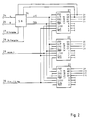
- an incremental encoder 1 known per se is provided.
- Such incremental encoders consist, for example, of a partial disk provided with optical markings, which is scanned by opto-electrical converters.
- One of the opto-electrical converters emits a pulse 0 during one revolution.
- tachometer signals A and B are generated, which are meandering and out of phase with one another by 90 °.
- the tachometer signals A and B each comprise 1024 pulses per revolution.
- the tachometer signals O, A and B are fed to the inputs of a switch 2, the other inputs of which are supplied with electronically generated test signals Test-0, Test-A and Test-B.
- the changeover switch can be controlled by the computer 3, so that the circuits described below can also be tested in a test mode when the machine is at a standstill.
- the tachometer signals A and B are evaluated to record the direction of rotation and the position as well as to measure the speed or speed. To detect the direction of rotation, the tachometer signals A and B are fed to a circuit 4.
- the circuit 4 has two outputs 5, 6, a signal to identify the direction of rotation being present at the output 5 and a pulse being emitted at the output 6 when the direction of rotation changes. While the signal indicating the direction of rotation is fed to a data input of the computer, the pulse at output 6 generates a program interruption (interrupt, IR).
- the speed is measured with two counters 8, 9, to which one of the tachometer signals A and B is fed via a changeover switch 7 and a frequency divider 17.
- the switch 7 is controlled by a circuit 18 such that if one of the tachometer signals fails, the other is forwarded.
- the frequency divider 17 is programmable, for which purpose the respective divider ratio is supplied from the computer 3 via the data bus 10.
- a counter signal is fed to the counters 8, 9, the frequency of which, according to the resolution of the speed measurement, is significantly higher than the frequency of the tachometer signals.
- the frequency of the reference signal can be varied. For this purpose, a corresponding value is fed to the oscillator 11 for the reference signal via the bus system 10.
- the speed is now measured in such a way that one of the counters alternately counts the pulses of the reference signal between two pulses emitted by the frequency divider 17.
- a program interruption IR
- the computer reads the counter reading via the data bus 10.
- the other counter has already been started, so that the duration of each period of the output signals of the frequency divider 17 is measured.
- the measured values are converted into speed values in computer 3.
- the tachometer signals A and B and the pulse 0 are fed to a counter circuit 12. It is also provided that pulse 0 triggers a program interruption.
- the counter circuit is reset by pulse 0, so that the counter reading indicates the position or the angle of rotation in relation to an initial position.
- this value is fed as an actual position to a comparator 13 and compared there with a target position which was previously written into a register 14 by the computer. If the machine has reached the target position, both values are the same and the comparator 13 triggers a program interruption, whereupon the computer initiates the measures provided for at the target position. Immediately afterwards, a new target position can be entered via register 14 can be entered. Until the machine reaches this new target position, it is not necessary to continuously record the position of the machine in the computer.
- additional pulses can be supplied to the counter circuit from an additional pulse generator 15, the frequency of which corresponds to a multiple of the frequency of the tachometer signals.
- the oscillator 15 is controlled by the computer 3 based on the frequency measurement using the circuits 7 to 11.
- the counting of the additional pulses gives the least significant digits of the actual position supplied to the comparator 13. Due to the inertia of the machine, the frequency of the tachometer signals does not change too quickly, so that the frequency measurement and thus the control of the oscillator 15 for the subsequent periods of the tachometer signal take place with sufficient accuracy.
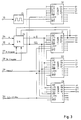
- FIG. 2 shows an exemplary embodiment for the counter circuit 12 (FIG. 1), in which three 4-bit counters of the type LS 669 are provided. Carry outputs of counters 21 and 22 are connected to inputs of counters 22 and 23, so that there is a total of a 12-bit counter.
- the tachometer signals A and B are fed via inputs 24, 25 to a switching network 26, where an up / down signal U / by means of a logical combination with the two least significant digits Q1 and Q2 of the counter reading.
- D and a counter enable signal ENA be derived.
- the signals DR specification and DR enable are fed to the switching network 26 via inputs 27, 28.
- the DR default signal indicates the direction of rotation of the machine.
- the DR enable signal indicates whether the speed of the machine is above or below a speed at which a change in direction can take place.
- Another input 29 is provided for pulse 0, which controls the LOAD input and thus resets the counters, since the data inputs A to D are at ground potential.
- the counter circuit 12 has an input 30 for a clock signal CLK.
- the resolution when determining the position can be increased by generating 15 additional pulses with the help of an oscillator, the frequency of which is a multiple of the frequency of the clock signals.
- the oscillator 15 generates pulses with 64 times the tacho frequency, which are fed to a further counter 31 of the type LS 669.
- the counting direction of the further counter 31 is controlled by the DR preset signal. This increases the counter reading to 16 digits (Q1 'to Q4', Q1 to Q12) and increases the resolution to 16 times, since a fourfold counting frequency is already achieved by evaluating both edges of the tachometer signals A and B.
- the switching network comprises an antivalence circuit 41 and two equivalence circuits 42, 43.
- the tachometer signals A, B are fed via inputs 24, 25 to both inputs of the antivalence circuit 41.
- the output of the antivalence circuit 41 is connected to an input of the equivalence circuit 43, at the other input of which the least significant bit (LSB) Q1 is present.
- the release signal can be output 44 ENA for the counter.
- To obtain an up / down signal U / D the tacho signal A and the second least significant digit Q2 of the counter reading are fed to the equivalence circuit 42, at the output 45 of which the signal U / D can be removed.
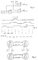
- FIG. 5 shows time diagrams of the signals O, A and B for a predetermined direction of rotation, for example for clockwise rotation.
- values of Q1 and Q2 of the counter 21 and the total count Q1 to Q12 are indicated in FIG.
- the counter reading Q1 'to Q4' (Fig. 3) is indicated.
- the signal O occurs once during each revolution, while the tachometer signals A and B occur more frequently according to the division of the incremental encoder - for example 1024 times per revolution.
- the tachometer signals A and B are 90 ° out of phase with each other.
- the counter is reset by pulse 0, so that the counter reading becomes 0 and the two least significant digits Q1 and Q2 also assume the value 0.
- a and B become different sizes, so that the value 1 is at the output of the antivalence circuit 41.
- U / D 1, which causes the counter to increment (count up).
- the switching network 26 including the two least significant digits of the counter 21, can then assume the states Z0, Z1, Z2 and Z3.
- the values present at the outputs Q1 and Q2 in these states are specified in the circles representing the states.
- a transition from one state to another can only take place in the sense of counting up or down, which is indicated in FIG. 6 by arrows between the circles.
- the filtering effect of the switching network is explained using the example of an interference pulse 46 (FIG. 5).
- the switching network shown in FIG. 4 thus has the effect that only the respectively neighboring states are permitted in any state. Counter reading 0 can therefore only be followed by counter reading 1 or 4095.
- Another Increasing operational reliability is achieved by specifying the direction of rotation via the computer 3 (FIG. 1). A change in the direction of rotation indicated by the tachometer signals A and B is recognized as an error if this contradicts the signal DR specification supplied by the computer. However, this additional check can lead to errors at standstill or at low speeds and is therefore switched off if a change of direction is possible due to low speeds. A further DR release signal is therefore supplied by the computer, which assumes the value 1 above a predetermined speed.
- the switching network according to FIG. 7 contains an antivalence circuit 50, an AND circuit 51 and an OR circuit 52.
- this counter can only be blocked if the value 1 is supplied to both inputs of the AND circuit 51. This is the case when both the DR enable signal has the value 1 and the two signals U / which are obtained independently of one another and which characterize the direction of rotation. D and DR specification are different from each other.
Description
Die Erfindung betrifft eine Anordnung zur Auswertung von Signalen eines Inkrementalgebers, insbesondere bei einer Druckmaschine, wobei mindestens zwei gegeneinander phasenverschobene Tachosignale erzeugt werden, die gezählt werden, wenn eine zulässige Kombination der Tachosignale vorliegt.The invention relates to an arrangement for evaluating signals from an incremental encoder, in particular in the case of a printing press, at least two tachometer signals being phase-shifted relative to one another, which are counted when there is a permissible combination of the tachometer signals.
Um die Position eines Maschinenteils, insbesondere die Drehlage eines rotierenden Maschinenteils, zu ermitteln und für Steuerungs- bzw. Regelzwecke zu verwenden, ist es bekannt, mit Hilfe eines Inkrementalgebers zwei gegeneinander phasenverschobene Tachosignale zu erzeugen und deren einzelne Impulse zu zählen. Dabei kann es jedoch zu Fehlern kommen, wenn den Tachosignalen Störimpulse überlagert sind. Diese Impulse können beispielsweise durch Einstreuungen in Verbindungsleitungen zwischen dem Inkrementalgeber und einem Steuergerät entstehen. Ferner kann eine Ursache für Störimpulse auch im Inkrementalgeber selbst liegen, wenn beispielsweise lichtundurchlässige Teilchen in einen optischen Inkrementalgeber eindringen.In order to determine the position of a machine part, in particular the rotational position of a rotating machine part, and to use it for control purposes, it is known to use an incremental encoder to generate two tacho signals that are phase-shifted with respect to one another and to count their individual pulses. However, errors can occur if interference signals are superimposed on the speedometer signals. These impulses can arise, for example, from interference in connection lines between the incremental encoder and a control unit. Furthermore, a cause of interference pulses can also lie in the incremental encoder itself, for example if opaque particles penetrate an optical incremental encoder.
Es ist bereits eine Schaltungsanordnung zur digitalen Verarbeitung mehrphasiger Impulsfolgen eines Impulsgebers bekannt (DE 36 36 000 A1), bei welcher vor einem Vorwärts-Rückwärts-Zähler ein Impulsumsetzer vorgesehen ist, in welchem eine Auslassung einzelner Impulse oder eine Versetzung von Impulsflanken der Impulsfolge stattfindet. Dieses dient dazu, die Frequenz der vom Impulsgeber abgeleiteten Impulse zu teilen, um einen gewünschten Maßstab für die Anzeige der Bewegung einer Maschine zu erhalten. Ein Schutz gegen gestörte Impulse ist damit nicht verbunden.A circuit arrangement for the digital processing of multi-phase pulse trains of a pulse generator is already known (DE 36 36 000 A1), in which a pulse converter is provided in front of an up-down counter, in which an omission of individual pulses or a displacement of pulse edges of the pulse train takes place. This serves to divide the frequency of the pulses derived from the pulse generator in order to obtain a desired scale for displaying the movement of a machine. Protection against disturbed impulses is not associated with this.
Es sind ferner Schaltungsanordnungen bekannt (DE 33 18 351 C2, DE 32 19 894 C2), bei welchen besondere Vorkehrungen getroffen sind, um die Drehrichtung zu erkennen und Unsicherheiten im Bereich einer Richtungsumkehr zu verhindern. Besondere Maßnahmen zur Sicherung gegen Störimpulse sind jedoch auch hier nicht vorhanden.Circuit arrangements are also known (DE 33 18 351 C2, DE 32 19 894 C2), in which special precautions are taken to detect the direction of rotation and to prevent uncertainties in the area of a reversal of direction. However, special measures to protect against interference pulses are not available here either.
Bei einer weiteren bekannten Schaltungsanordnung (DE 29 30 793 C2) sollen ebenfalls Störungen verhindert werden, die auf Pendelungen der Maschine im Bereich der Übergänge zwischen verschiedenen Signalpegeln beruhen, also im wesentlichen im Stillstand der Maschine bei eingeschalteter Steuerung auftreten. Dazu ist bei dieser Schaltungsanordnung vorgesehen, daß die Impulslängen und die Impulspausen der Impulsfolgen gleich oder in etwa gleich groß sind, daß die Impulsfolgen an Eingänge eines Exklusiv-Oder-Gliedes gelegt sind, das zeitverzögert die Takteingänge zweier an ihren Eingängen von je einer der Impulsfolgen beaufschlagten Flip-Flops speist, deren Ausgangssignale an ein Exklusiv-Oder-Glied gelegt sind, dem eine digital arbeitende Weg- bzw. Positionserfassungseinrichtung nachgeschaltet ist. Diese bekannte Schaltungsanordnung eliminiert jedoch nur Störungen innerhalb eines bestimmten Zeitbereichs und ist somit für Störimpulse, die innerhalb eines großen Drehzahlbereichs auftreten können, nicht geeignet.In another known circuit arrangement (
Schließlich ist ein fehlergesichertes inkrementales Wegmeßsystem bekannt (DAS 2 207 224), bei welchem im Inkrementalgeber mehr als zwei, insbesondere vier Abtaster, zwei Zähler und ein Vergleicher für die beiden Zählerstände vorgesehen sind. Dieses bedeutet jedoch einen erheblichen Aufwand bezüglich der Abtasteinrichtungen und der Auswertungsschaltung.Finally, an error-protected incremental position measuring system is known (
Aufgabe der Erfindung ist es, eine einwandfreie Auswertung von Signalen eines Inkrementalgebers zu ermöglichen, auch wenn diese gestört sind.The object of the invention is to enable a correct evaluation of signals from an incremental encoder, even if they are disturbed.
Die erfindungsgemäße Anordnung ist dadurch gekennzeichnet, daß einem Zähler ein Schaltnetz vorgeschaltet ist, daß die Tachosignale dem Schaltnetz zuführbar sind, und daß Ausgänge des Zählers mit Eingängen des Schaltnetzes verbunden sind.The arrangement according to the invention is characterized in that a switching network is connected upstream of a counter, that the tacho signals can be fed to the switching network, and that outputs of the counter are connected to inputs of the switching network.
Gemäß Weiterbildungen der erfindungsgemäßen Anordnungs ist vorgesehen, daß ein Signal zur Steuerung der Zählrichtung durch Vergleich eines der Tachosignale mit der zweitgeringstwertigen Stelle des Zählerstandes erzeugt wird und daß ein Freigabesignal, welches eine Zählung der Tachosignale ermöglicht, durch einen Vergleich zweier Tachosignale und einem anschließenden Vergleich mit der geringstwertigen Stelle des Zählerstandes erzeugt wird.According to developments of the arrangement according to the invention, it is provided that a signal for controlling the counting direction is generated by comparing one of the tachometer signals with the second least significant digit of the counter reading, and that an enable signal, which enables counting of the tachometer signals, by comparing two tachometer signals and then comparing them with the least significant digit of the meter reading is generated.
Eine weitere Erhöhung der Störsicherheit wird gemäß einer anderen Weiterbildung der Erfindung dadurch erzielt, daß ein unabhängig von den Tachosignalen abgeleitetes Richtungssignal mit aus den Tachosignalen abgeleiteten Signalen zur Steuerung der Zählrichtung verknüpft wird und daß das durch die Verknüpfung gewonnene Signal mit einem aus den Tachosignalen abgeleiteten Freigabesignal zur Bildung eines weiteren Freigabesignals verknüpft wird.A further increase in interference immunity is achieved according to another development of the invention in that a direction signal derived independently of the tachometer signals is linked to signals derived from the tachometer signals for controlling the counting direction, and in that the signal obtained by the linkage is linked to a release signal derived from the tachometer signals is linked to form a further release signal.
Gemäß einer vorteilhaften Ausgestaltung dieser Weiterbildung wird ein Fehlverhalten bei geringen Geschwindigkeiten dadurch vermieden, daß ein Geschwindigkeitssignal abgeleitet wird, welches bei einer vorgegebenen Geschwindigkeit des Inkrementalgebers von einem ersten in einen zweiten logischen Zustand übergeht, und daß das Geschwindigkeitssignal mit dem Signal zur Steuerung der Zählrichtung und dem Richtungssignal derart verknüpft wird, daß eine Zählung der Tachosignale bei geringeren Geschwindigkeiten ununterbrochen erfolgt.According to an advantageous embodiment of this development, malfunction at low speeds is avoided in that a speed signal is derived which changes from a first to a second logic state at a predetermined speed of the incremental encoder, and in that the speed signal with the signal for controlling the counting direction and the direction signal is linked in such a way that the tachometer signals are counted continuously at lower speeds.
Diese Anordnung zeichnet sich einerseits durch einen geringen Aufwand aus, andererseits wird bei der Verwendung eines einem Rechner vorgeschalteten Zählers der Rechner von der laufenden Zählung der Impulse entlastet. Bei einer vorteilhaften Weiterbildung der Anordnung ist vorgesehen, daß weiteren Eingängen des Schaltnetzes ein Richtungssignal und ein Geschwindigkeitssignal, welches bei einer vorgegebenen Geschwindigkeit des Inkrementalgebers von einem ersten in einen zweiten logischen Zustand übergeht, zuführbar sind. Damit wird in einfacher Weise eine weitere Überprüfung der Tachosignale ermöglicht.This arrangement is characterized on the one hand by a low outlay, on the other hand the computer is relieved of the current counting of the pulses when using a counter upstream of a computer. In an advantageous development of the arrangement, it is provided that further inputs of the switching network can be supplied with a direction signal and a speed signal, which changes from a first to a second logic state at a predetermined speed of the incremental encoder. A further check of the tachometer signals is thus made possible in a simple manner.
Zur weiteren Erhöhung der Betriebssicherheit trägt eine andere Weiterbildung der erfindungsgemäßen Anordnung bei, die darin besteht, daß zwischen dem Inkrementalgeber und dem Schaltnetz ein Umschalter angeordnet ist, mit dem Testsignale aufschaltbar sind. Hierdurch wird ein einfacher Selbsttest der erfindungsgemäßen Anordnung ermöglicht, der beispielsweise automatisch bei dem Einschalten der Maschine durchgeführt werden kann.Another development of the arrangement according to the invention, which consists in the fact that a changeover switch is arranged between the incremental encoder and the switching network, with which test signals can be applied, contributes to the further increase in operational reliability. This enables a simple self-test of the arrangement according to the invention, which can be carried out automatically, for example, when the machine is switched on.
Ausführungsbeispiele der Erfindung sind in der Zeichnung anhand mehrerer Figuren dargestellt und in der nachfolgenden Beschreibung näher erläutert. Es zeigt:
- Fig. 1 eine Anordnung zur Auswertung von Tachosignalen mit einem Ausführungsbeispiel der erfindungsgemäßen Anordnung,
- Fig. 2 ein erstes Ausführungsbeispiel,
- Fig. 3 ein weiteres Ausführungsbeispiel,
- Fig. 4 ein Schaltnetz, das Teil der Schaltungen nach den
Figuren 2 und 3 ist, - Fig. 5 Zeitdiagramme einiger bei der Anordnung nach Fig. 2 verwendeter Signale.
- Fig. 6 einen Automatengraphen zur Erläuterung der Funktion des Schaltnetzes und
- Fig. 7 ein weiteres Schaltnetz.
- 1 shows an arrangement for evaluating speedometer signals with an embodiment of the arrangement according to the invention,
- 2 shows a first embodiment,
- 3 shows a further exemplary embodiment,
- 4 shows a switching network which is part of the circuits according to FIGS. 2 and 3,
- Fig. 5 timing diagrams of some signals used in the arrangement of Fig. 2.
- Fig. 6 is a machine graph to explain the function of the switching network and
- Fig. 7 shows another switching network.
Gleiche Teile sind in den Figuren mit gleichen Bezugszeichen versehen.Identical parts are provided with the same reference symbols in the figures.
Bei der Anordnung nach Fig. 1 ist ein an sich bekannter Inkrementalgeber 1 vorgesehen. Derartige Inkrementalgeber bestehen beispielsweise aus einer mit optischen Markierungen versehenen Teilscheibe, die von opto-elektrischen Wandlern abgetastet wird. Dabei gibt einer der opto-elektrischen Wandler während einer Umdrehung einen Impuls 0 ab. Ferner werden Tachosignale A und B erzeugt, die mäanderförmig und zueinander um 90° phasenverschoben sind. Bei einem gebräuchlichen Inkrementalgeber umfassen die Tachosignale A und B jeweils 1024 Impulse pro Umdrehung.In the arrangement according to FIG. 1, an
Die Tachosignale O, A und B werden Eingängen eines Umschalters 2 zugeführt, dessen weitere Eingänge mit elektronisch erzeugten Testsignalen Test-0, Test-A und Test-B beaufschlagt sind. Der Umschalter ist vom Rechner 3 steuerbar, so daß in einer Test-Betriebsart die im folgenden beschriebenen Schaltungen auch im Stillstand der Maschine getestet werden können.The tachometer signals O, A and B are fed to the inputs of a
Die Tachosignale A und B werden zur Erfassung der Drehrichtung und der Position sowie zur Messung der Geschwindigkeit bzw. Drehzahl ausgewertet. Zur Erfassung der Drehrichtung werden die Tachosignale A und B einer Schaltung 4 zugeführt. In diesem Zusammenhang, und zur Erläuterung wird auf die enropäische Patentanmeldung 89106294.5 verwiesen. Die Schaltung 4 weist zwei Ausgänge 5,6 auf, wobei am Ausgang 5 ein Signal zur Kennzeichnung der Drehrichtung ansteht und am Ausgang 6 ein Impuls bei Änderung der Drehrichtung abgegeben wird. Während das die Drehrichtung kennzeichnende Signal einem Dateneingang des Rechners zugeführt wird, erzeugt der Impuls am Ausgang 6 eine Programmunterbrechung (Interrupt, IR).The tachometer signals A and B are evaluated to record the direction of rotation and the position as well as to measure the speed or speed. To detect the direction of rotation, the tachometer signals A and B are fed to a
Die Messung der Drehzahl erfolgt mit zwei Zählern 8,9, denen über einen Umschalter 7 und einen Frequenzteiler 17 eines der Tachosignale A bzw. B zugeführt wird. Dabei wird der Umschalter 7 von einer Schaltung 18 derart gesteuert, daß bei Ausfall eines der Tachosignale das andere weitergeleitet wird. Der Frequenzteiler 17 ist programmierbar, wozu das jeweilige Teilerverhältnis über den Datenbus 10 vom Rechner 3 zugeführt wird. Den Zählern 8,9 wird ein Referenzsignal zugeführt, dessen Frequenz entsprechend der Auflösung der Drehzahlmessung wesentlich höher als die Frequenz der Tachosignale ist. Um auch bei hohen Drehzahlen eine hohe Auflösung der Drehzahmessung zu erreichen, ohne daß bei niedrigen Drehzahlen die Zähler 8,9 überlaufen, kann die Frequenz des Referenzsignals variiert werden. Dazu wird ein entsprechender Wert über das Bussystem 10 dem Oszillator 11 für das Referenzsignal zugeführt.The speed is measured with two
Die Messung der Drehzahl erfolgt nun derart, daß abwechselnd einer der Zähler zwischen zwei vom Frequenzteiler 17 abgegebenen Impulsen die Impulse des Referenzsignals zählt. Nach Beendigung des Zählvorganges wird eine Programmunterbrechung (IR) ausgelöst, worauf der Rechner den Zählerstand über den Datenbus 10 liest. Inzwischen wurde bereits der andere Zähler gestartet, so daß die Dauer einer jeden Periode der Ausgangssignale des Frequenzteilers 17 gemessen wird. Die Meßwerte werden im Rechner 3 in Drehzahlwerte umgerechnet.The speed is now measured in such a way that one of the counters alternately counts the pulses of the reference signal between two pulses emitted by the
Da zum Einlesen des Zählerstandes jeweils eine Programmunterbrechung ausgelöst wird, werden dadurch andere Programmabläufe im Rechner gestört. Um diese Störungen nicht zu häufig auftreten zu lassen, wird bei höheren Drehzahlen die Frequenz der Tachosignale A und B - wie bereits beschrieben - geteilt. Der Datenbus und der Rechner sind stark vereinfacht dargestellt, da geeignete Schaltungen und Bausteine hinreichend bekannt sind.Since a program interruption is triggered to read the meter reading, this interferes with other program sequences in the computer. In order not to allow these interferences to occur too frequently, the frequency of the tachometer signals A and B is divided - as already described - at higher speeds. The data bus and the computer are shown in a highly simplified manner, since suitable circuits and components are well known.
Zur Erfassung der Position werden die Tachosignale A und B und der Impuls 0 einer Zählerschaltung 12 zugeführt. Außerdem ist vorgesehen, daß der Impuls 0 eine Programmunterbrechung auslöst. Durch den Impuls 0 wird die Zählerschaltung rückgesetzt, so daß der Zählerstand die Position bzw. den Drehwinkel bezogen auf eine Anfangsstellung angibt. Dieser Wert wird bei der Anordnung nach Fig. 1 als Ist-Position einem Vergleicher 13 zugeführt und dort mit einer Soll-Position, welche vorher vom Rechner in ein Register 14 eingeschrieben wurde, verglichen. Ist die Maschine bei der Soll-Position angelangt, so sind beide Werte gleich und der Vergleicher 13 löst eine Programmunterbrechung aus, worauf der Rechner die bei der Soll-Position vorgesehenen Maßnahmen veranlaßt. Unmittelbar danach kann über das Register 14 eine neue Soll-Position eingegeben werden. Bis die Maschine diese neue Soll-Position erreicht, ist im Rechner keine laufende Erfassung der Position der Maschine erforderlich.To detect the position, the tachometer signals A and B and the
Zur Erhöhung der Auflösung bei der Positionsermittlung können der Zählerschaltung Zusatzimpulse von einem Zusatzimpulsgenerator 15 zugeführt werden, deren Frequenz einem Vielfachen der Frequenz der Tachosignale entspricht. Dazu wird der Oszillator 15 vom Rechner 3 aufgrund der Frequenzmessung mit Hilfe der Schaltungen 7 bis 11 gesteuert. Die Zählung der Zusatzimpulse ergibt die niederwertigen Stellen der dem Vergleicher 13 zugeführten Ist-Position. Bedingt durch die Trägkeit der Maschine, ändert sich die Frequenz der Tachosignale nicht allzu schnell, so daß die Frequenzmessung und damit die Steuerung des Oszillators 15 für die nachfolgenden Perioden des Tachosignals mit ausreichender Genauigkeit erfolgen.To increase the resolution when determining the position, additional pulses can be supplied to the counter circuit from an
Fig. 2 zeigt ein Ausführungsbeispiel für die Zählerschaltung 12 (Fig. 1), bei welchem drei 4-Bit-Zähler vom Typ LS 669 vorgesehen sind. Übertragsausgänge der Zähler 21 und 22 sind mit Eingängen der Zähler 22 und 23 verbunden, so daß sich insgesamt ein 12-Bit-Zähler ergibt. Die Tachosignale A und B werden über Eingänge 24, 25 einem Schaltnetz 26 zugeführt, wo durch logische Verknüpfung mit den beiden niederwertigen Stellen Q1 und Q2 des Zählerstandes ein Aufwärts/Abwärtssignal U/
Wie bereits im Zusammenhang mit Fig. 1 erläutert, kann die Auflösung bei der Ermittlung der Position dadurch erhöht werden, daß mit Hilfe eines Oszillators 15 weitere Impulse erzeugt werden, deren Frequenz ein Vielfaches der Frequenz der Taktsignale beträgt. Bei dem in Fig. 3 dargestellten Ausführungsbeispiel erzeugt der Oszillator 15 Impulse mit 64-facher Tachofrequenz, die einem weiteren Zähler 31 vom Typ LS 669 zugeführt werden. Die Zählrichtung des weiteren Zählers 31 wird vom Signal DR-Vorgabe gesteuert. Damit wird der Zählerstand auf 16 Stellen (Q1′ bis Q4′, Q1 bis Q12) erweitert und die Auflösung auf das 16-fache erhöht, da durch die Auswertung beider Flanken der Tachosignale A und B bereits eine vierfache Zählfrequenz erzielt wird. Die Winkelauflösung beträgt bei einer Teilung von 1024 pro Vollkreis demnach 360/4096 = 0,0879 Grad ohne den weiteren Zähler 31 und 360/(4096*16) = 0,0055 Grad mit dem weiteren Zähler 31.As already explained in connection with FIG. 1, the resolution when determining the position can be increased by generating 15 additional pulses with the help of an oscillator, the frequency of which is a multiple of the frequency of the clock signals. In the exemplary embodiment shown in FIG. 3, the
Fig. 4 zeigt ein Ausführungsbeispiel für das Schaltnetz 26, bei welchem die Signale DR-Freigabe und DR-Vorgabe nicht berücksichtigt werden. Das Schaltnetz umfaßt eine Antivalenz-Schaltung 41 sowie zwei Äquivalenz-Schaltungen 42, 43. Die Tachosignale A, B werden über die Eingänge 24, 25 beiden Eingängen der Antivalenz-Schaltung 41 zugeführt. Der Ausgang der Antivalenzschaltung 41 ist mit einem Eingang der Äquivalenz-Schaltung 43 verbunden, an deren anderem Eingang das geringstwertige Bit (LSB) Q1 anliegt. Am Ausgang 44 kann das Freigabesignal
Die Funktion des Schaltnetzes nach Fig. 4 in Verbindung mit dem Zähler nach Fig. 2 wird im folgenden anhand von Fig. 5 näher erläutert. Fig. 5 zeigt Zeitdiagramme der Signale O, A und B für eine vorgegebene Drehrichtung, beispielsweise für Rechtslauf. Außerdem sind in Fig. 5 Werte von Q1 und Q2 des Zählers 21 und der gesamte Zählerstand Q1 bis Q12 angegeben. Schließlich ist der Zählerstand Q1′ bis Q4′ (Fig. 3) angedeutet.The function of the switching network according to FIG. 4 in connection with the counter according to FIG. 2 is explained in more detail below with reference to FIG. 5. 5 shows time diagrams of the signals O, A and B for a predetermined direction of rotation, for example for clockwise rotation. In addition, values of Q1 and Q2 of the
Das Signal O tritt einmal während jeder Umdrehung auf, während die Tachosignale A und B entsprechend der Teilung des Inkrementalgebers häufiger auftreten - beispielsweise 1024 mal pro Umdrehung. Die Tachosignale A und B sind um 90° gegeneinander phasenverschoben. Durch den Impuls 0 wird der Zähler rückgesetzt, so daß der Zählerstand 0 wird und damit auch die beiden niederwertigen Stellen Q1 und Q2 den Wert 0 annehmen. Nach der ersten darauffolgenden Flanke des Tachosignals A werden A und B verschieden groß, so daß am Ausgang der Antivalenz-Schaltung 41 der Wert 1 liegt. Durch Verknüpfung mit Q1 = 0 in der Äquivalenz-Schaltung 43 wird der Ausgang 44 ebenfalls zu 0, was eine Freigabe des Zählers bewirkt. Da zu diesem Zeitpunkt Q2 = 0 ist und A = 0 wird, wird U/
Durch die Inkrementierung des Zählers wird Q1 = 1, was wiederum bewirkt, daß bei der folgenden Flanke des Tachosignals B die Gleichheit der Tachosignale A und B zu
Zu Beginn der darauffolgenden Viertelperiode der Tachosignale springt das Signal A auf 1, da jedoch Q2 ebenfalls = 1 ist, wird U/
Zur weiteren Erläuterung der Funktion des Schaltnetzes gemäß Fig. 4 in Verbindung mit der Zählerschaltung, insbesondere mit dem Zähler 21 (Fig. 2) wird im folgenden auf den Automatengraphen gemäß Fig. 6 Bezug genommen. Danach kann das Schaltnetz 26 einschließlich der beiden niederwertigen Stellen des Zählers 21 die Zustände Z0, Z1, Z2 und Z3 einnehmen. Die bei diesen Zuständen an den Ausgängen Q1 und Q2 anstehenden Werte sind in den die Zustände darstellenden Kreisen angegeben. Ein Übergang von einem Zustand in einen anderen kann nur im Sinne eines Aufwärts- bzw. Abwärtszählen erfolgen, was in Fig. 6 durch Pfeile zwischen den Kreisen angedeutet ist. Dabei bedeuten die Zahlen an den Pfeilen die für den jeweiligen Übergang erforderlichen Werte der Tachosignale A und B. So wird beispielsweise ein Übergang vom Zustand Z0 zum Zustand Z1 durch A = 0 und B = 1 verursacht. Wird danach B = 0, so geht das Schaltnetz in den Zustand 2 über.For further explanation of the function of the switching network according to FIG. 4 in connection with the counter circuit, in particular with the counter 21 (FIG. 2), reference is made below to the machine graph according to FIG. 6. The
Am Beispiel eines Störimpulses 46 (Fig. 5) wird die Filterwirkung des Schaltnetzes erläutert. Vor dem Störimpuls befindet sich das Schaltnetz im Zustand Z3. Dadurch, daß während des Störimpulses 46 das Tachosignal B den Wert 1 annimmt, erfolgt ein Weiterschalten in den Zustand Z0, da auch das Tachosignal A = 1 ist. Am Ende des Störimpulses wird jedoch wieder B = 0, so daß das Schaltnetz in den Zustand Z3 zurückgesetzt wird. Der Zähler wird also durch den Störimpuls 46 inkrementiert, nach dem Störimpuls jedoch wieder dekrementiert, so daß keine Verfälschung des Zählergebnisses erfolgt.The filtering effect of the switching network is explained using the example of an interference pulse 46 (FIG. 5). The switching network is in state Z3 before the interference pulse. Characterized in that the tacho signal B assumes the
Das in Fig. 4 dargestellte Schaltnetz bewirkt also, daß in einem beliebigen Zustand nur die jeweils benachbarten Zustände zugelassen werden. Auf den Zählerstand 0 kann also nur einer der Zählerstände 1 oder 4095 folgen. Eine weitere Erhöhung der Betriebssicherheit wird durch die Vorgabe der Drehrichtung über den Rechner 3 (Fig. 1) gewonnen. Dabei wird eine durch die Tachosignale A und B angezeigte Änderung der Drehrichtung als Fehler erkannt, wenn dieses im Widerspruch zu dem vom Rechner zugeführten Signal DR-Vorgabe steht. Diese zusätzliche Prüfung kann allerdings bei Stillstand oder kleinen Drehzahlen zu Fehlern führen und wird daher abgeschaltet, wenn aufgrund geringer Drehzahlen ein Drehrichtungswechsel möglich ist. Es wird daher vom Rechner ein weiteres Signal DR-Freigabe zugeführt, das oberhalb einer vorgegebenen Drehzahl den Wert 1 annimmt.The switching network shown in FIG. 4 thus has the effect that only the respectively neighboring states are permitted in any state. Counter reading 0 can therefore only be followed by counter reading 1 or 4095. Another Increasing operational reliability is achieved by specifying the direction of rotation via the computer 3 (FIG. 1). A change in the direction of rotation indicated by the tachometer signals A and B is recognized as an error if this contradicts the signal DR specification supplied by the computer. However, this additional check can lead to errors at standstill or at low speeds and is therefore switched off if a change of direction is possible due to low speeds. A further DR release signal is therefore supplied by the computer, which assumes the
Das Schaltnetz gemäß Fig. 7 enthält zusätzlich zu den bereits im Zusammenhang mit Fig. 4 erläuterten Teilen eine Antivalenz-Schaltung 50, eine Und-Schaltung 51 und eine Oder-Schaltung 52. Das Ausgangssignal
Dieses Sperren des Zählers kann jedoch nur erfolgen, wenn beiden Eingängen der Und-Schaltung 51 der Wert 1 zugeführt wird. Dieses ist der Fall, wenn sowohl das Signal DR-Freigabe den Wert 1 aufweist, als auch die beiden unabhängig voneinander gewonnenen die Drehrichtung kennzeichnenden Signale U/
Claims (8)
Applications Claiming Priority (2)
| Application Number | Priority Date | Filing Date | Title |
|---|---|---|---|
| DE3815533A DE3815533C1 (en) | 1988-05-06 | 1988-05-06 | |
| DE3815533 | 1988-05-06 |
Publications (2)
| Publication Number | Publication Date |
|---|---|
| EP0340481A1 EP0340481A1 (en) | 1989-11-08 |
| EP0340481B1 true EP0340481B1 (en) | 1992-03-04 |
Family
ID=6353835
Family Applications (1)
| Application Number | Title | Priority Date | Filing Date |
|---|---|---|---|
| EP89106295A Expired - Lifetime EP0340481B1 (en) | 1988-05-06 | 1989-04-10 | Arrangement for evaluating the signals of an incremental transmitter |
Country Status (6)
| Country | Link |
|---|---|
| US (1) | US4982413A (en) |
| EP (1) | EP0340481B1 (en) |
| JP (1) | JPH0217415A (en) |
| AU (1) | AU619825B2 (en) |
| CA (1) | CA1308775C (en) |
| DE (2) | DE3815533C1 (en) |
Cited By (1)
| Publication number | Priority date | Publication date | Assignee | Title |
|---|---|---|---|---|
| DE102005006694A1 (en) * | 2005-02-15 | 2006-08-24 | Conti Temic Microelectronic Gmbh | Method and device for determining the position of an adjusting drive |
Families Citing this family (8)
| Publication number | Priority date | Publication date | Assignee | Title |
|---|---|---|---|---|
| DE3815534A1 (en) * | 1988-05-06 | 1989-11-16 | Heidelberger Druckmasch Ag | SYSTEM FOR DETECTING THE POSITION OF MOVING MACHINE PARTS |
| DE3815530A1 (en) * | 1988-05-06 | 1989-11-16 | Heidelberger Druckmasch Ag | METHOD OF DETERMINING THE SPEED OF A MACHINE |
| JP2697919B2 (en) * | 1989-09-29 | 1998-01-19 | キヤノン株式会社 | Signal interpolation circuit and displacement measuring device provided with the circuit |
| JP2714651B2 (en) * | 1990-06-29 | 1998-02-16 | 富士通株式会社 | Counter circuit |
| DE4137979B4 (en) * | 1991-11-19 | 2004-05-06 | Heidelberger Druckmaschinen Ag | Drive for a printing press with at least two mechanically decoupled printing units |
| DE4321179A1 (en) * | 1993-06-25 | 1995-01-05 | Heidelberger Druckmasch Ag | Method and device for controlling or regulating the operations of a printing machine |
| CN100340416C (en) * | 2004-01-30 | 2007-10-03 | 明基电通股份有限公司 | Correcting device and method and ink jet printer with correcter |
| DE102006048851A1 (en) | 2006-10-16 | 2008-04-17 | Siemens Ag | Drive unit i.e. electric motor, position detecting device for e.g. sliding door, has encoder whose position is detected with accuracy described by increment, and converter reducing accuracy of detection to accuracy described by increment |
Citations (5)
| Publication number | Priority date | Publication date | Assignee | Title |
|---|---|---|---|---|
| DE2207224A1 (en) * | 1972-02-16 | 1973-08-23 | ||
| DE3219894C2 (en) * | 1982-05-27 | 1984-08-30 | Danfoss A/S, Nordborg | Incremental-to-digital converter |
| DE3318351C2 (en) * | 1983-05-20 | 1986-05-22 | Preh, Elektrofeinmechanische Werke Jakob Preh Nachf. Gmbh & Co, 8740 Bad Neustadt | Circuit arrangement for a speed and direction of rotation dependent evaluation circuit of an incremental direction of rotation pulse generator |
| DE3636000A1 (en) * | 1985-11-07 | 1987-05-14 | Simmering Graz Pauker Ag | CIRCUIT ARRANGEMENT FOR DIGITAL PROCESSING OF MULTI-PHASE IMPULSE SEQUENCES OF AN IMPULSE SENSOR |
| DE2930793C2 (en) * | 1979-07-28 | 1988-03-31 | Licentia Patent-Verwaltungs-Gmbh, 6000 Frankfurt, De |
Family Cites Families (11)
| Publication number | Priority date | Publication date | Assignee | Title |
|---|---|---|---|---|
| US3740532A (en) * | 1971-05-25 | 1973-06-19 | Kureha Chemical Ind Co Ltd | Digital counter averaging system |
| FR2153526A5 (en) * | 1971-09-14 | 1973-05-04 | Charbonnages De France | |
| DE2352975A1 (en) * | 1973-10-23 | 1975-04-30 | Teldix Gmbh | Magnitude and direction of relative movement - includes measurement of the component relative movement with respect to another component |
| US4475086A (en) * | 1982-03-31 | 1984-10-02 | Eastman Kodak Company | Duty cycle detector |
| JPS60107521A (en) * | 1983-11-16 | 1985-06-13 | Sumitomo Electric Ind Ltd | Rotary sensor |
| US4715051A (en) * | 1985-04-12 | 1987-12-22 | Giardina Joseph J | Electronic potentiometer |
| JPS62285009A (en) * | 1986-06-03 | 1987-12-10 | Nec Corp | Position detecting apparatus |
| JPS6347612A (en) * | 1986-08-13 | 1988-02-29 | Mitsutoyo Corp | Displacement detector |
| US4844610A (en) * | 1988-04-29 | 1989-07-04 | Becton, Dickinson And Company | Backflow isolator and capture system |
| DE3815534A1 (en) * | 1988-05-06 | 1989-11-16 | Heidelberger Druckmasch Ag | SYSTEM FOR DETECTING THE POSITION OF MOVING MACHINE PARTS |
| DE3815535A1 (en) * | 1988-05-06 | 1989-11-16 | Heidelberger Druckmasch Ag | METHOD AND ARRANGEMENT FOR MEASURING THE SPEED OF A MACHINE |
-
1988
- 1988-05-06 DE DE3815533A patent/DE3815533C1/de not_active Expired
-
1989
- 1989-03-28 CA CA000594889A patent/CA1308775C/en not_active Expired - Lifetime
- 1989-04-10 DE DE8989106295T patent/DE58900893D1/en not_active Expired - Lifetime
- 1989-04-10 EP EP89106295A patent/EP0340481B1/en not_active Expired - Lifetime
- 1989-04-20 AU AU33207/89A patent/AU619825B2/en not_active Ceased
- 1989-05-02 JP JP1112287A patent/JPH0217415A/en active Pending
- 1989-05-08 US US07/348,990 patent/US4982413A/en not_active Expired - Fee Related
Patent Citations (5)
| Publication number | Priority date | Publication date | Assignee | Title |
|---|---|---|---|---|
| DE2207224A1 (en) * | 1972-02-16 | 1973-08-23 | ||
| DE2930793C2 (en) * | 1979-07-28 | 1988-03-31 | Licentia Patent-Verwaltungs-Gmbh, 6000 Frankfurt, De | |
| DE3219894C2 (en) * | 1982-05-27 | 1984-08-30 | Danfoss A/S, Nordborg | Incremental-to-digital converter |
| DE3318351C2 (en) * | 1983-05-20 | 1986-05-22 | Preh, Elektrofeinmechanische Werke Jakob Preh Nachf. Gmbh & Co, 8740 Bad Neustadt | Circuit arrangement for a speed and direction of rotation dependent evaluation circuit of an incremental direction of rotation pulse generator |
| DE3636000A1 (en) * | 1985-11-07 | 1987-05-14 | Simmering Graz Pauker Ag | CIRCUIT ARRANGEMENT FOR DIGITAL PROCESSING OF MULTI-PHASE IMPULSE SEQUENCES OF AN IMPULSE SENSOR |
Cited By (1)
| Publication number | Priority date | Publication date | Assignee | Title |
|---|---|---|---|---|
| DE102005006694A1 (en) * | 2005-02-15 | 2006-08-24 | Conti Temic Microelectronic Gmbh | Method and device for determining the position of an adjusting drive |
Also Published As
| Publication number | Publication date |
|---|---|
| DE3815533C1 (en) | 1989-11-30 |
| CA1308775C (en) | 1992-10-13 |
| AU3320789A (en) | 1989-11-09 |
| US4982413A (en) | 1991-01-01 |
| EP0340481A1 (en) | 1989-11-08 |
| DE58900893D1 (en) | 1992-04-09 |
| AU619825B2 (en) | 1992-02-06 |
| JPH0217415A (en) | 1990-01-22 |
Similar Documents
| Publication | Publication Date | Title |
|---|---|---|
| EP0349716B1 (en) | System for the detection of the position of moving machine parts | |
| DE2851853C2 (en) | Method and device for detecting the angular position of a rotating part | |
| DE2616972B2 (en) | Method and circuit arrangement for digitally measuring the period of a rotating component, for example a vehicle wheel | |
| CH635423A5 (en) | MEASURING DEVICE FOR CAPACITIVELY DETERMINING THE RELATIVE LOCATIONS OF TWO MOVING PARTS. | |
| DE2553806C3 (en) | Circuit arrangement for digital measurement of the period of an alternating voltage | |
| EP0340481B1 (en) | Arrangement for evaluating the signals of an incremental transmitter | |
| DE3640413C2 (en) | Measuring arrangement | |
| AT392536B (en) | LINEAR, INCREMENTAL MEASURING SYSTEM | |
| DE2724696C3 (en) | Method for determining the unbalance angle and device for this | |
| EP2331912B1 (en) | Arrangement and method for generating a reference impulse for a position measuring device | |
| EP0233618A2 (en) | Motion detector | |
| EP0203275A2 (en) | Incremental transducer | |
| EP0062698A2 (en) | Evaluation circuit for a digital rotational speed transducer | |
| DE3815535A1 (en) | METHOD AND ARRANGEMENT FOR MEASURING THE SPEED OF A MACHINE | |
| EP0220547A1 (en) | Revolution measurement sensor circuit | |
| DE2333530A1 (en) | MEASURING ARRANGEMENT FOR CONVERTING A DISTANCE INTO A CODED SIGNAL | |
| DE102017205267A1 (en) | Position measuring device and method for operating a position measuring device | |
| DE2353039A1 (en) | Magnetic field angular aspect meter - has a pickup in the form of a probe for the geomagnetic field | |
| DE2621179C2 (en) | Circuit arrangement for detecting the direction of rotation of rotating parts | |
| CH395559A (en) | Digital angle measuring device | |
| DE3509682C2 (en) | ||
| DE3330500C2 (en) | Circuit arrangement for interference suppression | |
| EP0183932B1 (en) | Pulse generator for converting the movement of a generator into a pulse train | |
| DE2554771A1 (en) | Rotating shaft monitoring system using direction discriminator - uses pulse counting system which eliminates superposed interference movements | |
| DE4403218C2 (en) | Encoder |
Legal Events
| Date | Code | Title | Description |
|---|---|---|---|
| PUAI | Public reference made under article 153(3) epc to a published international application that has entered the european phase |
Free format text: ORIGINAL CODE: 0009012 |
|
| 17P | Request for examination filed |
Effective date: 19890410 |
|
| AK | Designated contracting states |
Kind code of ref document: A1 Designated state(s): CH DE FR GB IT LI SE |
|
| 17Q | First examination report despatched |
Effective date: 19910129 |
|
| GRAA | (expected) grant |
Free format text: ORIGINAL CODE: 0009210 |
|
| AK | Designated contracting states |
Kind code of ref document: B1 Designated state(s): CH DE FR GB IT LI SE |
|
| REF | Corresponds to: |
Ref document number: 58900893 Country of ref document: DE Date of ref document: 19920409 |
|
| PGFP | Annual fee paid to national office [announced via postgrant information from national office to epo] |
Ref country code: SE Payment date: 19920414 Year of fee payment: 4 |
|
| PGFP | Annual fee paid to national office [announced via postgrant information from national office to epo] |
Ref country code: DE Payment date: 19920509 Year of fee payment: 4 |
|
| ITF | It: translation for a ep patent filed |
Owner name: STUDIO JAUMANN |
|
| ET | Fr: translation filed | ||
| GBT | Gb: translation of ep patent filed (gb section 77(6)(a)/1977) | ||
| PLBE | No opposition filed within time limit |
Free format text: ORIGINAL CODE: 0009261 |
|
| STAA | Information on the status of an ep patent application or granted ep patent |
Free format text: STATUS: NO OPPOSITION FILED WITHIN TIME LIMIT |
|
| 26N | No opposition filed | ||
| PG25 | Lapsed in a contracting state [announced via postgrant information from national office to epo] |
Ref country code: SE Effective date: 19930411 |
|
| PGFP | Annual fee paid to national office [announced via postgrant information from national office to epo] |
Ref country code: CH Payment date: 19930625 Year of fee payment: 5 |
|
| PG25 | Lapsed in a contracting state [announced via postgrant information from national office to epo] |
Ref country code: DE Effective date: 19940101 |
|
| PG25 | Lapsed in a contracting state [announced via postgrant information from national office to epo] |
Ref country code: LI Effective date: 19940430 Ref country code: CH Effective date: 19940430 |
|
| REG | Reference to a national code |
Ref country code: CH Ref legal event code: PL |
|
| EUG | Se: european patent has lapsed |
Ref document number: 89106295.2 Effective date: 19931110 |
|
| PGFP | Annual fee paid to national office [announced via postgrant information from national office to epo] |
Ref country code: GB Payment date: 19960325 Year of fee payment: 8 |
|
| PGFP | Annual fee paid to national office [announced via postgrant information from national office to epo] |
Ref country code: FR Payment date: 19960402 Year of fee payment: 8 |
|
| PG25 | Lapsed in a contracting state [announced via postgrant information from national office to epo] |
Ref country code: GB Effective date: 19970410 |
|
| GBPC | Gb: european patent ceased through non-payment of renewal fee |
Effective date: 19970410 |
|
| PG25 | Lapsed in a contracting state [announced via postgrant information from national office to epo] |
Ref country code: FR Free format text: LAPSE BECAUSE OF NON-PAYMENT OF DUE FEES Effective date: 19971231 |
|
| REG | Reference to a national code |
Ref country code: FR Ref legal event code: ST |
|
| PG25 | Lapsed in a contracting state [announced via postgrant information from national office to epo] |
Ref country code: IT Free format text: LAPSE BECAUSE OF NON-PAYMENT OF DUE FEES;WARNING: LAPSES OF ITALIAN PATENTS WITH EFFECTIVE DATE BEFORE 2007 MAY HAVE OCCURRED AT ANY TIME BEFORE 2007. THE CORRECT EFFECTIVE DATE MAY BE DIFFERENT FROM THE ONE RECORDED. Effective date: 20050410 |