EP0203275A2 - Incremental transducer - Google Patents
Incremental transducer Download PDFInfo
- Publication number
- EP0203275A2 EP0203275A2 EP86102705A EP86102705A EP0203275A2 EP 0203275 A2 EP0203275 A2 EP 0203275A2 EP 86102705 A EP86102705 A EP 86102705A EP 86102705 A EP86102705 A EP 86102705A EP 0203275 A2 EP0203275 A2 EP 0203275A2
- Authority
- EP
- European Patent Office
- Prior art keywords
- sensor
- signal
- rotation
- output
- voltage
- Prior art date
- Legal status (The legal status is an assumption and is not a legal conclusion. Google has not performed a legal analysis and makes no representation as to the accuracy of the status listed.)
- Withdrawn
Links
Images

Classifications
-
- G—PHYSICS
- G01—MEASURING; TESTING
- G01B—MEASURING LENGTH, THICKNESS OR SIMILAR LINEAR DIMENSIONS; MEASURING ANGLES; MEASURING AREAS; MEASURING IRREGULARITIES OF SURFACES OR CONTOURS
- G01B7/00—Measuring arrangements characterised by the use of electric or magnetic techniques
- G01B7/02—Measuring arrangements characterised by the use of electric or magnetic techniques for measuring length, width or thickness
-
- G—PHYSICS
- G01—MEASURING; TESTING
- G01D—MEASURING NOT SPECIALLY ADAPTED FOR A SPECIFIC VARIABLE; ARRANGEMENTS FOR MEASURING TWO OR MORE VARIABLES NOT COVERED IN A SINGLE OTHER SUBCLASS; TARIFF METERING APPARATUS; MEASURING OR TESTING NOT OTHERWISE PROVIDED FOR
- G01D5/00—Mechanical means for transferring the output of a sensing member; Means for converting the output of a sensing member to another variable where the form or nature of the sensing member does not constrain the means for converting; Transducers not specially adapted for a specific variable
- G01D5/12—Mechanical means for transferring the output of a sensing member; Means for converting the output of a sensing member to another variable where the form or nature of the sensing member does not constrain the means for converting; Transducers not specially adapted for a specific variable using electric or magnetic means
- G01D5/14—Mechanical means for transferring the output of a sensing member; Means for converting the output of a sensing member to another variable where the form or nature of the sensing member does not constrain the means for converting; Transducers not specially adapted for a specific variable using electric or magnetic means influencing the magnitude of a current or voltage
- G01D5/142—Mechanical means for transferring the output of a sensing member; Means for converting the output of a sensing member to another variable where the form or nature of the sensing member does not constrain the means for converting; Transducers not specially adapted for a specific variable using electric or magnetic means influencing the magnitude of a current or voltage using Hall-effect devices
- G01D5/147—Mechanical means for transferring the output of a sensing member; Means for converting the output of a sensing member to another variable where the form or nature of the sensing member does not constrain the means for converting; Transducers not specially adapted for a specific variable using electric or magnetic means influencing the magnitude of a current or voltage using Hall-effect devices influenced by the movement of a third element, the position of Hall device and the source of magnetic field being fixed in respect to each other
-
- G—PHYSICS
- G01—MEASURING; TESTING
- G01P—MEASURING LINEAR OR ANGULAR SPEED, ACCELERATION, DECELERATION, OR SHOCK; INDICATING PRESENCE, ABSENCE, OR DIRECTION, OF MOVEMENT
- G01P3/00—Measuring linear or angular speed; Measuring differences of linear or angular speeds
- G01P3/42—Devices characterised by the use of electric or magnetic means
- G01P3/44—Devices characterised by the use of electric or magnetic means for measuring angular speed
- G01P3/46—Devices characterised by the use of electric or magnetic means for measuring angular speed by measuring amplitude of generated current or voltage
Definitions
- the invention is based on an incremental encoder according to the type of the main claim.
- the invention can be used generally for incremental displacement measurement or rotation angle measurement, a rotor with a surface structure changing in the direction of travel, i.e. broken surface, which can also move in a straight line, being opposed to a sensor which reacts to the surface structure change with a change in the output voltage emitted by it . Since the invention is preferably suitable for use in connection with magnetoresistive differential sensors, known systems of this type are explained below.
- a field plate differential sensor constructed in this way is preferably suitable for scanning gear structures and therefore in particular for detecting the angle of rotation, also measuring the speed of rotation, whereby the resolution of an incremental angle of rotation sensor formed in this way, but also of other basic elements of angle of rotation sensors based on inductive or capacitive measurement, is decisive for the distance between the sensor and the incremental wheel (e.g. gear) depends.
- the maximum permissible diameter of the respective encoder or increment wheel and the number of pulses to be emitted by the sensor per revolution are prescribed, which leads to a discrepancy between the requirements and the feasibility with known sensor means if, for example, a motor vehicle ABS wheel sensor Air gap of a predetermined size, for example 4 mm, requires that due to the conditions of the components involved, to ensure perfect functioning, however, only significantly smaller air gaps (approx. 2 mm) can be realized.
- An empirical value for magnetic sensor systems can be assumed, which indicates a relationship between the increment width W (for example, the tooth spacing ZA in the case of an increment wheel) and the maximum realizable air gap, that is, the distance from the magnetic field-sensitive areas of the sensor.
- the present invention is therefore based on the object of decisively improving the resolution of such an incremental displacement sensor, preferably an angle of rotation sensor, so that, while maintaining the respective number of pulses, there is the possibility of increasing the distance between the receiver and the rotor (increment wheel), or in any case larger ones Allow clearances.
- the travel encoder according to the invention solves this problem with the characterizing features of the main claim and has the advantage that the resolution is significantly improved, so that either by using coarser circumferential structures of the rotor or increment wheel with the same specific number of pulses the distance or air gap can be increased accordingly, or at Maintaining the respective geometric conditions and using at least two sensor systems, a resolution capacity that is twice as high can be achieved.
- the invention is equally well applicable to straight-toothed Helical gears or helical gears with helical gearing, in which case the two sensor systems can be arranged one above the other or one below the other to achieve a particularly small expansion in the circumferential or moving direction of the rotor or incremental gear.
- the measures listed in the subclaims permit advantageous further developments and improvements of the travel sensor specified in the main claim.
- the invention can be used particularly advantageously for speed measurement at the lowest speeds, and a good measure of the respective instantaneous speed can also be obtained in the time between the incremental zero crossings.
- the type of signal acquisition in the present invention namely by the arrangement of at least two separate, possibly also different sensor systems, allows a clear distinction to be made between a forward or a backward movement of the rotor or increment wheel and is displayed in the form of a high or low output signal.
- FIG. 1 shows a highly schematic view of the structure and assignment of the displacement sensor (increment wheel) and sensor systems
- FIG. 2 shows a possible embodiment of an electrical or electronic evaluation circuit of the output signals supplied by the sensors
- FIG. 3 different voltage profiles of sensor output signals and the common output voltage obtained by linking.
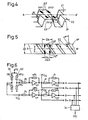
- FIG. 4 shows, as a further exemplary embodiment, the variant of sensor systems aligned with one another in the case of rotor structures offset in the direction of movement, likewise FIG. 5, in which the rotor structure consists of helical teeth
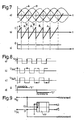
- FIG. 6 shows a further exemplary embodiment of the invention for speed measurement at the lowest speeds as a circuit diagram 7 and FIG. 7 voltage curves over time, as they result at different circuit points of FIG. 6.
- FIGS. 8 and 9 show another possible application of the invention for detecting the direction of the relative movement between the rotor (increment wheel) and the sensor unit.
- the invention is based on the knowledge that a coarser design of the circumferential structures of the increment wheel, as the respective displacement sensor or rotor is to be referred to in the following, initially (apparently) results in a reduction in the specific number of pulses emitted, but on the other hand such coarser circumferential structures can also be scanned at a greater distance between the pickup or sensor and the increment wheel; For example, one can expect that if the tooth spacing ZA (or generally the increment width W) is doubled, the possible sensor distance to the increment wheel, that is to say the air gap, can be doubled.
- the further step in the present invention then consists in that a second sensor system is used to maintain the original number of pulses in order to avoid a corresponding halving of the achievable number of pulses approximately per revolution of the increment wheel (with the same wheel diameter), specifically in its positioning on the circumference of the increment wheel that its output signal is offset from the first sensor system by a quarter period ( ⁇ / 2).
- a displacement of the respective output signals of the sensor systems can also be achieved with a parallel alignment of the sensor systems to one another by means of a correspondingly offset circumferential structure of the increment wheel.
- the invention is not limited to the use of magnetostrictive differential sensors, that is to say transducers working with field plate resistors, but basically any sensors can be used whose output signal e , corresponding to the changing geometric structure of the increment wheel, a corresponding change its output voltage ze ig en .It is also possible assigned a field plate resistor differential sensor to use and elsewhere, this for the invention at one location and about the respective quarter period offset to arrange a pair of sensors of different functions.
- the first field plate differential sensor S1 represented by the field plate pair FP1 and FP2, and a second field plate differential sensor S2, represented by the field plate pair FP3 and FP4, and is preferably arranged in the same housing, which is possible without problems is.
- the second sensor S2 (or the second sensor system) consisting of the second pair of field plates FP3 and FP4 is offset from one another by a quarter period, based on the geometric structure of the increment wheel, i.e. by the fourth part of the tooth spacing ZA, the spacing of the respective a field plate pair forming field plate resistances, as is usual with such differential sensors, is half the tooth spacing FA.
- the increment wheel is only partially shown with R, the teeth formed by this and opposite the entire sensor area with ZP1, ZR2, ZR3 ... designated.
- the two field plate resistors each forming a sensor system S1, S2, are electrically connected in series and are connected to a supply voltage Uo, the connection of the two field plate resistors each being connected to one input of a downstream comparator K, whose other input is supplied with half the supply voltage Uo / 2.
- This simple circuit enables the normally sinusoidal voltages tapped by the respective sensor S1, S2 to be converted into square-wave signals, the repetition rate of which initially corresponds to only half of the initially required number of pulses, as can be easily seen and as in a) and b) in Fig. 3 in the form of Curves are specified.
- the voltage U 12 represents the individual sensor voltage output by the comparator K1 for the sensor S and the voltage U 34 represents the individual sensor voltage output by the comparator K2 for the sensor S2, the courses of which in a) and b) over the angle of rotation of the increment wheel or over time are applied.
- the offset voltage curve of the two digitally available individual output voltages U 12 and U 34 by a quarter of a period above the angle of rotation Y or over time enables them to be linked to a common signal output voltage with the aid of a gate circuit G1 which is designed such that the signal output voltage Ua is only formed at the gate output if only one or the other voltage is high; with simultaneously high signals, low or zero signals result at the output of the gate circuit G1.
- Such a gate can best be implemented as an EXCLUSIVE-OR circuit or by any other logic circuit which enables a corresponding signal combination. It can be seen that in this way, as shown at c) in FIG. 3, twice the desired number of pulses per revolution is obtained despite the coarser circumferential structure (larger tooth spacing ZA) of the increment wheel.
- the comparators K1, K2 and the gate linking the two output voltages can be attached directly to the sensor on site, so that only three lines are required, namely for + Uo, ground and signal Ua. If the electronic components are housed in a switching device further away, four lines are required for the sensor housing, namely + Uo, ground, signal U 12 , signal U 34 .
- the two sensors S1 'and S2' can also be on the same circumferential position, i.e. with their Field plates FP1 ', FP2' or FP3 ', FP4' aligned with each other, but have the scanned increment wheel R 'in the circumferential or rotational direction with mutually offset structures, for example tooth sequences Z1 and Z2 offset from one another by a quarter tooth spacing.
- the dimensions of the entire sensor area are smaller in the circumferential direction.
- a third variant for achieving the required quarter-period offset is shown in FIG. 5 and consists in the use of a helical toothing SZ of the incremental wheel R ", the respective field plate resistance pairs of the sensors S1" or S2 "again being arranged on the same circumferential position , but have an axial distance d from one another, which follows the following relationship: where ⁇ is the helix angle of the toothing.
- the basic principle of the present invention can also be applied to increment encoders or displacement encoders other than the radially toothed increment wheels shown so far.
- the same basic principle can be used with planar tooth structures, as often occur with ABS systems, with slotted or perforated disks, ring gears and the like.
- the measuring method according to the invention is independent of the sensor principle, so that instead of the field plate sensors shown, for example, to name but a few, permalloy, Hall, inductive and other sensors can also be used.
- the two sensors or sensor systems do not necessarily have to be mounted in a common housing at the same circumferential location of the increment wheel; due to the given periodicity of the circumferential structure, a shift by a quarter period of the two sensor signals can also be achieved if the sensors, each of which is preferably designed as a differential sensor, are mounted at far-away positions on the circumference, but always so that the quarter-period Displacement is realized.
- Such training can be very small in the case Wheels and large space constraints can also be useful, for example in ignition distributors and the like.
- Another preferred area of use for the present invention relates to the possibility of a speed measurement at low and lowest speeds. Such. Measurements are evaluated, for example, at very low speeds in order to determine the speed of rotation for the distances between the signal zero crossings, for example counted, as is usually the case; this may result in the problem of measurement times which are much too long, since no new information is generated between two zero crossings.
- the measuring times can be significantly shortened if, for example, from the approximately sinusoidal to triangular sensor individual signal curves, not only the zero crossings but also intermediate analog values are evaluated as a measure for the rotational speed measurement.
- inverting amplifiers each having a resistance R in the entrance and in the feedback path are then added to the voltage waveforms ⁇ and B (see in a) in Fig. 7) created nor the inverted, so 180 0 offset voltage curves A and B, so that the four voltage curves A, B, A ⁇ B ⁇ offset from each other by a quarter period or / 2 result.
- V-fold amplified signals A, B, A v, B ⁇ result in their assigned curve profiles corresponding to a) of FIG. 7.
- a further preferred field of application results alone or in connection with rotation angle measurements by the possibility of recognizing the respective direction of movement of the increment wheel or displacement sensor and preferably of making it evaluable by means of a separate signal.
- FIG. 8 shows the phase relationships of the signals mentioned over time as curves
- FIG. 9 shows a direction detection circuit.
- phase differences can be converted into an additional logic direction signal Q by a suitable evaluation circuit.
- Such a suitable evaluation circuit is shown in FIG. 9 and comprises a so-called D flip-flop, to which the voltage U 12 is supplied as a CLOCK signal.
Abstract
Description
Die Erfindung geht aus von einem inkrementalen Weggeber nach der Gattung des Hauptanspruchs. Die Erfindung kann allgemein bei der inkrementalen Wegmessung oder Drehwinkelmessung eingesetzt werden, wobei einem Rotor mit sich in Wegrichtung ändernder, also gebrochener Oberflächenstruktur, der sich auch geradlinig fortbewegen kann, ein Sensor gegenüberliegt, der auf die Oberflächenstrukturänderung mit einer Änderung der von ihm abgegebenen Ausgangsspannung reagiert. Da die Erfindung sich für die Anwendung in Verbindung mit magnetoresistiven Differentialsensoren bevorzugt eignet, werden bekannte Systeme dieser Art im folgenden erläutert. Der Aufbau solcher aus magnetfeldabhängigen Widerständen bestehender und daher als sogenannte Feldplatten-Differentialsensoren bezeichnete Sensorsysteme ist üblicherweise so, daß zwei magnetfeldabhängige Widerstände in Reihe an eine Gleichspannungsquelle angeschlossen und am Verbindungspunkt der Widerstände die jeweilige Sensorausgangsspannung abgegeben wird (siehe Siemens-Datenbuch Band 1 "Sensoren", Seiten 60-69).The invention is based on an incremental encoder according to the type of the main claim. The invention can be used generally for incremental displacement measurement or rotation angle measurement, a rotor with a surface structure changing in the direction of travel, i.e. broken surface, which can also move in a straight line, being opposed to a sensor which reacts to the surface structure change with a change in the output voltage emitted by it . Since the invention is preferably suitable for use in connection with magnetoresistive differential sensors, known systems of this type are explained below. The construction of such sensor systems consisting of magnetic field dependent resistors and therefore referred to as so-called field plate differential sensors is usually such that two magnetic field dependent resistors in Series connected to a DC voltage source and the respective sensor output voltage is output at the connection point of the resistors (see Siemens
Ein solchermaßen aufgebauter Feldplatten-Differentialsensor eignet sich vorzugsweise zur Abtastung von Zahnradstrukturen und daher insbesondere zur Drehwinkelerfassung, auch Drehgeschwindigkeitsmessung, wobei das Auflösungsvermögen eines so gebildeten inkrementalen Drehwinkelsensors, aber auch aus anderen Grundelementen bestehender Drehwinkelsensoren auf induktiver oder kapazitiver Meßgrundlage, entscheidend vom Abstand Aufnehmer-Inkrementrad (beispielsweise also Zahnrad) abhängt. Üblicherweise sind der maximal zulässige Durchmesser des jeweiligen Gebers oder Inkrementrades sowie die pro Umdrehung mindestens von dem Sensor abzugebende Pulszahl vorgeschrieben, was zu einer Diskrepanz zwischen den Anforderungen und der Realisierbarkeit mit bekannten Sensormitteln führt, wenn man, beispielsweise für einen Kraftfahrzeug-ABS-Radsensor einen Luftspalt vorgegebener Größe, beispielsweise 4 mm, fordert, aufgrund der Gegebenheiten der beteiligten Komponenten zur Sicherstellung einer einwandfreien Funktion aber nur wesentlich geringere Luftspalte (ca. 2 mm) höchstens realisierbar sind. Dabei kann von einem Erfahrungswert für magnetische Sensorsysteme ausgegangen werden, der eine Beziehung zwischen der Inkrementweite W (beispielsweise also bei einem Inkrementrad dem Zahnabstand ZA) und dem maximal realisierbaren Luftspalt, also Abstand zu den magnetfeldempfindlichen Bereichen des Sensors angibt. Dieser Erfahrungswert liegt bei Luftspalt LS = W/3. Angewendet auf das obige Beispiels beispielsweise eines ABS-Radsensors mit zulässigem Durchmesser des Inkrementrades in numerischen Werten von 190 mm und der pro Umdrehung mindestens abzugebenderPPulszahl von 100 ergibt sich bei einem Zahnabstand von 6 mm lediglich die Möglichkeit eines maximalen Luftspalts von 2 mm, was einer ursprünglichen Forderung von 4 mm nicht gerecht wird.A field plate differential sensor constructed in this way is preferably suitable for scanning gear structures and therefore in particular for detecting the angle of rotation, also measuring the speed of rotation, whereby the resolution of an incremental angle of rotation sensor formed in this way, but also of other basic elements of angle of rotation sensors based on inductive or capacitive measurement, is decisive for the distance between the sensor and the incremental wheel (e.g. gear) depends. Usually, the maximum permissible diameter of the respective encoder or increment wheel and the number of pulses to be emitted by the sensor per revolution are prescribed, which leads to a discrepancy between the requirements and the feasibility with known sensor means if, for example, a motor vehicle ABS wheel sensor Air gap of a predetermined size, for example 4 mm, requires that due to the conditions of the components involved, to ensure perfect functioning, however, only significantly smaller air gaps (approx. 2 mm) can be realized. An empirical value for magnetic sensor systems can be assumed, which indicates a relationship between the increment width W (for example, the tooth spacing ZA in the case of an increment wheel) and the maximum realizable air gap, that is, the distance from the magnetic field-sensitive areas of the sensor. This empirical value is at air gap LS = W / 3. Ange Turning to the above example, for example an ABS wheel sensor with a permissible diameter of the increment wheel in numerical values of 190 mm and the minimum number of pulses to be emitted per revolution of 100, with a tooth spacing of 6 mm there is only the possibility of a maximum air gap of 2 mm, which is an original Requirement of 4 mm does not meet.
Der vorliegenden Erfindung liegt daher die Aufgabe zugrunde, das Auflösungsvermögen eines solchen inkrementalen Weggebers, vorzugsweise Drehwinkelsensors entscheidend zu verbessern, so daß sich bei Beibehaltung der jeweiligen Impulszahl die Möglichkeit ergibt, den Abstand zwischen Aufnahmer und Rotor (Inkrementrad) zu vergrößern, oder jedenfalls hier größere Abstände zuzulassen.The present invention is therefore based on the object of decisively improving the resolution of such an incremental displacement sensor, preferably an angle of rotation sensor, so that, while maintaining the respective number of pulses, there is the possibility of increasing the distance between the receiver and the rotor (increment wheel), or in any case larger ones Allow clearances.
Der erfindungsgemäße Weggeber löst diese Aufgabe mit den kennzeichnenden Merkmalen des Hauptanspruchs und hat den Vorteil, daß die Auflösung entscheidend verbessert wird, so daß entweder durch Zugrundelegung gröberer Umfangsstrukturen des Rotors oder Inkrementrades bei gleicher spezifischer Impulszahl der Abstand oder Luftspalt entsprechend vergrößert werden kann, oder bei Beibehaltung der jeweiligen geometrischen Gegebenheiten und bei Zugrundelegung von mindestens zwei Sensorsystemen ein entsprechend doppelt so hohes Auflösungsvermögen erzielt werden kann.The travel encoder according to the invention solves this problem with the characterizing features of the main claim and has the advantage that the resolution is significantly improved, so that either by using coarser circumferential structures of the rotor or increment wheel with the same specific number of pulses the distance or air gap can be increased accordingly, or at Maintaining the respective geometric conditions and using at least two sensor systems, a resolution capacity that is twice as high can be achieved.
Die Erfindung ist gleichermaßen gut einsetzbar bei geradverzahnten Stirnrädern oder auch Stirnrädern mit Schrägverzahnung, wobei in diesem Fall die beiden Sensorsysteme unter Erzielung einer besonders geringen Ausdehnung in Umfangs- oder Bewegungsrichtung des Rotors oder Inkrementrades aufeinander ausgerichtet über-oder untereinander angeordnet werden können.The invention is equally well applicable to straight-toothed Helical gears or helical gears with helical gearing, in which case the two sensor systems can be arranged one above the other or one below the other to achieve a particularly small expansion in the circumferential or moving direction of the rotor or incremental gear.
Durch die in den Unteransprüchen aufgeführten Maßnahmen sind vorteilhafte Weiterbildungen und Verbesserungen des im Hauptanspruch angegebenen Weggebers möglich. Besonders vorteilhaft läßt sich die Erfindung zur Geschwindigkeitsmessung bei niedrigsten Drehzahlen einsetzen, wobei auch in der Zeit zwischen den inkrementalen Nulldurchgängen ein gutes Maß der jeweiligen Momentangeschwindigkeit gewonnen werden kann.The measures listed in the subclaims permit advantageous further developments and improvements of the travel sensor specified in the main claim. The invention can be used particularly advantageously for speed measurement at the lowest speeds, and a good measure of the respective instantaneous speed can also be obtained in the time between the incremental zero crossings.
Schließlich läßt sich durch die Art der Signalgewinnung bei vorliegender Erfindung, nämlich durch die Anordnung mindestens zweier getrennter, gegebenenfalls auch unterschiedlicher Sensorsysteme eine klare Unterscheidung zwischen einer Vorwärts- oder einer Rückwärtsbewegung des Rotors oder Inkrementrades treffen und in Form eines hoch oder nieder liegenden Ausgangssignals anzeigen.Finally, the type of signal acquisition in the present invention, namely by the arrangement of at least two separate, possibly also different sensor systems, allows a clear distinction to be made between a forward or a backward movement of the rotor or increment wheel and is displayed in the form of a high or low output signal.
Ausführungsbeispiele der Erfindung sind in der Zeichnung dargestellt und werden in der nachfolgenden Beschreibung näher erläutert. Es zeigen Fig. 1 stark schematisiert im Ausschnitt Struktur und Zuordnung von Weggeber (Inkrementrad) und Sensorsystemen, Fig. 2 ein mögliches Ausführungsbeispiel einer elektrischen oder elektronischen Auswerteschaltung der von den Sensoren gelieferten Ausgangssignale und Fig. 3 verschiedene Spannungsverläufe von Sensorausgangssignalen sowie der gemeinsamen, durch Verknüpfung gewonnen Ausgangsspannung. Fig. 4 zeigt als weiteres Ausführungsbeispiel die Variante aufeinander ausgerichteter Sensorsysteme bei in Bewegungsrichtung versetzten Rotorstrukturen, desgleichen die Fig. 5, bei der die Rotorstruktur aus einer Schrägverzahnung besteht, während die Fig. 6 ein weiteres Ausführungsbeispiel der Erfindung zur Geschwindigkeitsmessung bei niedrigsten Drehzahlen als Schaltbild zeigt und die Fig. 7 Spannungsverläufe über der Zeit, wie sie sich an verschiedenen Schaltungspunkten der Fig. 6 ergeben. Schließlich zeigen die Fig. 8 und 9 noch eine Einsatzmöglichkeit der Erfindung zur Richtungserkennung der Relativbewegung zwischen Rotor (Inkrementrad) und Sensoreinheit.Embodiments of the invention are shown in the drawing and are explained in more detail in the following description. 1 shows a highly schematic view of the structure and assignment of the displacement sensor (increment wheel) and sensor systems, FIG. 2 shows a possible embodiment of an electrical or electronic evaluation circuit of the output signals supplied by the sensors and FIG. 3 different voltage profiles of sensor output signals and the common output voltage obtained by linking. FIG. 4 shows, as a further exemplary embodiment, the variant of sensor systems aligned with one another in the case of rotor structures offset in the direction of movement, likewise FIG. 5, in which the rotor structure consists of helical teeth, while FIG. 6 shows a further exemplary embodiment of the invention for speed measurement at the lowest speeds as a circuit diagram 7 and FIG. 7 voltage curves over time, as they result at different circuit points of FIG. 6. Finally, FIGS. 8 and 9 show another possible application of the invention for detecting the direction of the relative movement between the rotor (increment wheel) and the sensor unit.
Die Erfindung beruht auf der Erkenntnis, daß eine gröbere Gestaltung der Umfangsstrukturen des Inkrementrades, wie der jeweilige Weggeber oder Rotor im folgenden ausschließlich noch bezeichnet werden soll, zwar zunächst (scheinbar) eine Reduzierung der abgegebenen spezifischen Impulszahl zur Folge hat, andererseits aber solche gröbere Umfangsstrukturen auch mit größerem Abstand des Aufnehmers oder Sensors vom Inkrementrad abgetastet werden können; so kann man beispielsweise damit rechnen, daß bei einer Verdoppelung des Zahnabstandes ZA (oder allgemein der Inkrementweite W) auch etwa eine Verdoppelung des möglichen Sensorabstandes zum Inkrementrad, also des Luftspaltes, erreichbar ist.The invention is based on the knowledge that a coarser design of the circumferential structures of the increment wheel, as the respective displacement sensor or rotor is to be referred to in the following, initially (apparently) results in a reduction in the specific number of pulses emitted, but on the other hand such coarser circumferential structures can also be scanned at a greater distance between the pickup or sensor and the increment wheel; For example, one can expect that if the tooth spacing ZA (or generally the increment width W) is doubled, the possible sensor distance to the increment wheel, that is to say the air gap, can be doubled.
Der weiterführende Schritt bei vorliegender Erfindung besteht dann darin, daß zur Vermeidung einer entsprechenden Halbierung der erzielbaren Impulszahl etwa pro Umdrehung des Inkrementrades (bei gleichem Raddurchmesser) ein zweites Sensorsystem zur Erhaltung der ursprünglichen Impulszahl eingesetzt wird, und zwar so in seiner Positionierung am Umfang des Inkrementrades, daß sein Ausgangssignal gegenüber dem ersten Sensorsystem um eine viertel Periode (π/2) versetzt ist. Wie weiter unten noch ausführlich erläutert, läßt sich eine solche Versetzung der jeweiligen Ausgangssignale der Sensorsysteme auch bei paralleler Ausrichtung der Sensorsysteme zueinander durch eine entsprechend versetzte Umfangsstruktur des Inkrementrades erzielen.The further step in the present invention then consists in that a second sensor system is used to maintain the original number of pulses in order to avoid a corresponding halving of the achievable number of pulses approximately per revolution of the increment wheel (with the same wheel diameter), specifically in its positioning on the circumference of the increment wheel that its output signal is offset from the first sensor system by a quarter period (π / 2). As explained in detail below, such a displacement of the respective output signals of the sensor systems can also be achieved with a parallel alignment of the sensor systems to one another by means of a correspondingly offset circumferential structure of the increment wheel.
Es sei darauf hingewiesen, daß die Erfindung nicht auf die Anwendung von magnetostriktiven Differentialsensoren, also auf mit Feldplattenwiderständen arbeitenden Aufnehmern beschränkt ist, sondern grundsätzlich beliebige Sensoren Verwendung finden können, deren Ausgangssignale,abgestimmt auf die sich ändernde geometrische Struktur des Inkrementrades, eine entsprechende Änderung ihrer Ausgangssignalspannung zeigen.Es ist auch möglich, für die Erfindung an einer Stelle einen Feldplattenwiderstand-Differentialsensor zu verwenden und an anderer Stelle, diesem zugeordnet und um die jeweilige viertel Periode versetzt, ein Sensorpaar unterschiedlicher Funktionen anzuordnen.It should be pointed out that the invention is not limited to the use of magnetostrictive differential sensors, that is to say transducers working with field plate resistors, but basically any sensors can be used whose output signal e , corresponding to the changing geometric structure of the increment wheel, a corresponding change its output voltage ze ig en .It is also possible assigned a field plate resistor differential sensor to use and elsewhere, this for the invention at one location and about the respective quarter period offset to arrange a pair of sensors of different functions.
Die im folgenden im Detail angegebenen Erläuterungen der Erfindung beschränkt diese daher nicht auf die Anwendung magnetfeldabhängiger Widerstände im Sensorbereich.The explanations of the invention given in detail below therefore do not limit them to the use of magnetic field-dependent resistors in the sensor area.
In der schematischen Darstellung der Fig. 1 ist ein erster Feldplatten-Differentialsensor S1, dargestellt durch das Feldplattenpaar FP1 und FP2, sowie ein zweiter Feldplatten-Differentialsensor S2, dargestellt durch das Feldplattenpaar FP3 und FP4 vorgesehen und vorzugsweise im gleichen Gehäuse angeordnet, was problemlos möglich ist. Dabei ist der aus dem zweiten Feldplattenpaar FP3 und FP4 bestehende zweite Sensor S2 (oder das zweite Sensorsystem) um eine viertel Periode, bezogen auf die geometrische Struktur des Inkrementrades also um den vierten Teil des Zahnabstandes ZA, zueinander versetzt angeordnet, wobei der Abstand der jeweils ein Feldplattenpaar zueinander bildenden Feldplattenwiderstände, wie bei solchen Differentialsensoren üblich, den halben Zahnabstand FA beträgt. In Fig. 1 ist das nur teilweise dargestellte Inkrementrad mit R, die von diesem gebildeten und dem gesamten Sensorbereich gegenüberliegenden Zähne mit ZP1, ZR2, ZR3 ... bezeichnet.1 is a first field plate differential sensor S1, represented by the field plate pair FP1 and FP2, and a second field plate differential sensor S2, represented by the field plate pair FP3 and FP4, and is preferably arranged in the same housing, which is possible without problems is. The second sensor S2 (or the second sensor system) consisting of the second pair of field plates FP3 and FP4 is offset from one another by a quarter period, based on the geometric structure of the increment wheel, i.e. by the fourth part of the tooth spacing ZA, the spacing of the respective a field plate pair forming field plate resistances, as is usual with such differential sensors, is half the tooth spacing FA. In Fig. 1, the increment wheel is only partially shown with R, the teeth formed by this and opposite the entire sensor area with ZP1, ZR2, ZR3 ... designated.
Wie die Darstellung der Fig. 2 zeigt, sind die beiden, jeweils ein Sensorsystem S1, S2 bildenden Feldplattenwiderstände elektrisch in Reihe geschaltet und liegen an einer Versorgungsspannung Uo, wobei die Verbindung der beiden Feldplattenwiderstände jeweils mit dem einen Eingang eines nachgeschalteten Komparators K verbunden ist, dessen anderem Eingang die halbe Versorgungsspannung Uo/2 zugeführt ist. Durch diese einfache Schaltung lassen sich die von dem jeweiligen Sensor S1, S2 abgegriffenen und normalerweise sinusförmigen Spannungen in Rechtecksignale umsetzen, wobei deren Wiederholrate zunächst nur der Hälfte der anfangs vorausgesetzten, erforderlichen Impulszahl entspricht, wie ohne weiteres einzusehen und wie auch bei a) und bei b) in Fig. 3 in Form von Kurvenverläufen angegeben ist. Dabei stellt die Spannung U 12 die vom Komparator Kl für den Sensor S und die Spannung U34 die vom Komparator K2 für den Sensor S2 jeweils abgegebene Sensoreinzelspannung dar, deren Verläufe bei a) und b) über den Drehwinkel des Inkrementrades bzw. über der Zeit aufgetragen sind. Der versetzte Spannungsverlauf der beiden bereits digital vorliegenden Einzelaus- gangsspannungen U 12 und U 34 um eine viertel Periode über dem Drehwinkel Y bzw. über der Zeit ermöglicht jetzt deren Verknüpfung zu einer gemeinsamen Signalausgangsspannung mit Hilfe einer Gatterschaltung G1, die so ausgebildet ist, daß nur dann die Signalausgangsspannung Ua am Gatterausgang gebildet wird, wenn nur jeweils die eine oder die andere Spannung hochliegt; bei gleichzeitig hochliegenden Signalen ergibt sich am Ausgang der Gatterschaltung G1 niederliegendes oder Null-Signal. Ein solches Gatter läßt sich am besten als EXCLUSIV-ODER-Schaltung realisieren oder durch jede andere, eine entsprechende Signalverknüpfung ermöglichende Logikschaltung. Man erkennt, daß man auf diese Weise, wie bei c) in Fig. 3 dargestellt, jetzt die doppelte, also die gewünschte Impulszahl pro Umdrehung trotz gröberer Umfangsstruktur (größerem Zahnabstand ZA) des Inkrementrades erhält.As shown in FIG. 2, the two field plate resistors, each forming a sensor system S1, S2, are electrically connected in series and are connected to a supply voltage Uo, the connection of the two field plate resistors each being connected to one input of a downstream comparator K, whose other input is supplied with half the supply voltage Uo / 2. This simple circuit enables the normally sinusoidal voltages tapped by the respective sensor S1, S2 to be converted into square-wave signals, the repetition rate of which initially corresponds to only half of the initially required number of pulses, as can be easily seen and as in a) and b) in Fig. 3 in the form of Curves are specified. The voltage U 12 represents the individual sensor voltage output by the comparator K1 for the sensor S and the voltage U 34 represents the individual sensor voltage output by the comparator K2 for the sensor S2, the courses of which in a) and b) over the angle of rotation of the increment wheel or over time are applied. The offset voltage curve of the two digitally available individual output voltages U 12 and U 34 by a quarter of a period above the angle of rotation Y or over time enables them to be linked to a common signal output voltage with the aid of a gate circuit G1 which is designed such that the signal output voltage Ua is only formed at the gate output if only one or the other voltage is high; with simultaneously high signals, low or zero signals result at the output of the gate circuit G1. Such a gate can best be implemented as an EXCLUSIVE-OR circuit or by any other logic circuit which enables a corresponding signal combination. It can be seen that in this way, as shown at c) in FIG. 3, twice the desired number of pulses per revolution is obtained despite the coarser circumferential structure (larger tooth spacing ZA) of the increment wheel.
Die Komparatoren K1, K2 und das die beiden Ausgangsspannungen verknüpfende Gatter (EXCLUSIV-ODER-Schaltung) können vor Ort direkt beim Sensor angebracht sein, so daß insgesamt nur drei Leitungen erforderlich sind, nämlich für +Uo, Masse und Signal Ua. Sind die elektronischen Baukomponenten in einem weiter entfernten Schaltgerät untergebracht, dann benötigt man für das Sensorgehäuse vier Leitungen, nämlich +Uo, Masse, Signal U12, Signal U34.The comparators K1, K2 and the gate linking the two output voltages (EXCLUSIVE-OR circuit) can be attached directly to the sensor on site, so that only three lines are required, namely for + Uo, ground and signal Ua. If the electronic components are housed in a switching device further away, four lines are required for the sensor housing, namely + Uo, ground, signal U 12 , signal U 34 .
Da es entsprechend vorliegender Erfindung lediglich auf die Viertelperioden-Versetzung der Einzelausgangssignale ankommt, können, wie in Fig. 4 dargestellt, anstelle der zueinander versetzt angebrachten beiden Differentialsensoren S1, S2 die beiden Sensoren Sl' und S2' auch auf gleicher Umfangslage, also mit ihren Feldplatten FP1', FP2' bzw. FP3', FP4' zueinander ausgerichtet, das abgetastete Inkrementrad R' jedoch in Umfangs- bzw. Drehrichtung bei zueinander versetzte Strukturen aufweisen , beispielsweise also um einen viertel Zahnabstand zueinander versetzte Zahnabfolgen Z1 und Z2. Bei einer solchen Ausbildung sind die Abmessungen des gesamten Sensorbereichs in Umfangsrichtung geringer.Since, according to the present invention, it is only a matter of the quarter-period offset of the individual output signals, as shown in FIG. 4, instead of the two differential sensors S1, S2 which are offset from one another, the two sensors S1 'and S2' can also be on the same circumferential position, i.e. with their Field plates FP1 ', FP2' or FP3 ', FP4' aligned with each other, but have the scanned increment wheel R 'in the circumferential or rotational direction with mutually offset structures, for example tooth sequences Z1 and Z2 offset from one another by a quarter tooth spacing. With such a design, the dimensions of the entire sensor area are smaller in the circumferential direction.
Eine dritte Variante zur Erzielung der erforderlichen Viertelperioden-Versetzung ist in Fig. 5 dargestellt und besteht in der Verwendung einer Schrägverzahnung SZ des Inkrementrades R", wobei die jeweiligen Feldplatten-Widerstandspaare der Sensoren S1" bzw. S2" wiederum auf gleicher Umfangslage angeordnet sein können, zueinander jedoch einen axialen Abstand d aufweisen, der folgender Beziehung folgt:
Bei der geteilten Inkrementrad-Struktur entsprechend Fig. 4 ist es erforderlich, die den Gesamtsensor bildenden Feldplatten einigermaßen in der Mittenlage zur Trennlinie A-A' zu halten, während bei der in Fig. 5 gezeigten Schrägverzahnung die Position der den jeweiligen Differentialsensor bildenden Feldplatten-Widerstände - unter Einhaltung des Abstandes zueinander - über die gesamte axiale Zahnbreite ZB verschoben werden kann, ohne daß eine Verfälschung des Ausgangssignals eintritt. Es ist auch nicht auszuschließen, daß Schrägverzahnungen günstiger herstellbar oder jedenfalls an geeigneten Stellen zur Messung verfügbar sind als versetzte Zahnstrukturen entsprechend Fig. 4.In the case of the divided increment wheel structure according to FIG. 4, it is necessary to keep the field plates forming the overall sensor somewhat in the central position with respect to the dividing line AA ', while in the case of the helical toothing shown in FIG. 5, the position of the field plate resistors forming the respective differential sensor - while maintaining the distance from one another - can be displaced over the entire axial tooth width ZB without the output signal being falsified. It cannot be ruled out that helical gears can be manufactured more cheaply or in any case are available at suitable locations for measurement than offset tooth structures according to FIG. 4.
Es versteht sich, daß das Grundprinzip vorliegender Erfindung auch auf andere Inkrementgeber oder Weggeber als die bisher dargestellten radialverzahnten Inkrementräder angewendet werden kann. Das gleiche Grundprinzip ist einsetzbar bei planaren Zahnstrukturen, wie sie vielfach bei ABS-Systemen auftreten, bei Schlitz- oder Lochscheiben, Hohlrädern u. dgl. Dabei ist, wie eingangs schon erwähnt, das erfindungsgemäße Meßverfahren vom Aufnehmerprinzip unabhängig, so daß anstelle der dargestellten Feldplattensensoren beispielsweise auch, um nur einige zu nennen, Permalloy-, Hall-, Induktiv- und andere Sensoren angewendet werden können. Da lediglich die geometrische Versetzung um eine viertel Periode erforderlich ist, müssen die beiden Sensoren oder Sensorsysteme auch nicht unbedingt in einem gemeinsamen Gehäuse an der gleichen Umfangsstelle des Inkrementrades angebracht sein; aufgrund der gegebenen Periodizität der Umfangsstruktur kann eine Verschiebung um eine viertel Periode der beiden Sensorsignale auch erzielt werden, wenn die Sensoren, jeder für sich jeweils als Differentialsensor vorzugsweise ausgebildet, an weit entfernten Positionen des Umfangs angebracht sind, aber immer so, daß die Viertelperioden-Verschiebun g realisiert ist. Eine solche Ausbildung kann im Falle sehr kleiner Räder und großer Raumnot auch zweckmäßig sein, beispielsweise bei Zündverteilern u, dgl.It goes without saying that the basic principle of the present invention can also be applied to increment encoders or displacement encoders other than the radially toothed increment wheels shown so far. The same basic principle can be used with planar tooth structures, as often occur with ABS systems, with slotted or perforated disks, ring gears and the like. Like mentioned at the beginning, the measuring method according to the invention is independent of the sensor principle, so that instead of the field plate sensors shown, for example, to name but a few, permalloy, Hall, inductive and other sensors can also be used. Since only the geometric offset by a quarter period is required, the two sensors or sensor systems do not necessarily have to be mounted in a common housing at the same circumferential location of the increment wheel; due to the given periodicity of the circumferential structure, a shift by a quarter period of the two sensor signals can also be achieved if the sensors, each of which is preferably designed as a differential sensor, are mounted at far-away positions on the circumference, but always so that the quarter-period Displacement is realized. Such training can be very small in the case Wheels and large space constraints can also be useful, for example in ignition distributors and the like.
Ein weiteres bevorzugtes Einsatzgebiet für vorliegende Erfindung betrifft die Möglichkeit einer Geschwindigkeitsmessung bei niedrigen und niedrigsten Drehzahlen. Solche. Messungen werden beispielsweise bei sehr niedrigen Drehzahlen zum Ermitteln der Drehgeschwindigkeit für die Abstände der Signal-Nulldurchgänge ausgewertet, beispielsweise also ausgezählt, wie dies üblicherweise der Fall ist; dabei ergibt sich das Problem gegebenenfalls wesentlich zu langer Meßzeiten, da zwischen jeweils zwei Nulldurchgängen keine neuen Informationen entstehen.Another preferred area of use for the present invention relates to the possibility of a speed measurement at low and lowest speeds. Such. Measurements are evaluated, for example, at very low speeds in order to determine the speed of rotation for the distances between the signal zero crossings, for example counted, as is usually the case; this may result in the problem of measurement times which are much too long, since no new information is generated between two zero crossings.
Unter Zugrundelegung des erfindungsgemäßen Grundprinzips lassen sich jedoch die Meßzeiten dann wesentlich verkürzen, wenn von den beispielsweise in etwa sinus- bis dreieckförmigen Sensoreinzelsignalverläufen nicht nur die Nulldurchgänge, sondern auch dazwischenliegende Analogwerte als Maß für die Drehgeschwindigkeitsmessung ausgewertet werden.On the basis of the basic principle according to the invention, however, the measuring times can be significantly shortened if, for example, from the approximately sinusoidal to triangular sensor individual signal curves, not only the zero crossings but also intermediate analog values are evaluated as a measure for the rotational speed measurement.
Entsprechend der Darstellung der Fig. 6 werden an die Verbindungspunkte der beiden, jeweils einen Sensor S1, S2 bildenden Feldplattenwiderstände FP1, FP2 bzw. FP3, FP4.mit dem Verstärkungsfaktor v behaftete Inverter-Verstärker über Eingangswiderstände von jeweils R1 angeschlossen, so daß sich an den Ausgängen der Verstärker zunächst jeweils die, auch hier wieder um eine viertel Periode zueinander versetzten Spannungen -vU 34 und -vU 12 ergeben, die entsprechend Fig. 6 auch mit Ä und mit B (= -A bzw. -B) bezeichnet sind. Durch weiter nachgeschaltete invertierende Verstärker mit jeweils einem Widerstand R im Eingang und im Rückkopplungszweig werden dann zu den Spannungsverläufen Ä und B (siehe bei a) in Fig. 7) noch die invertierten, also um 1800 versetzten Spannungsverläufe A und B erzeugt, so daß sich die vier jeweils zueinander um eine viertel Periode oder /2 versetzten Spannungsverläufe A, B, A̅B̅ ergeben. 6, to the connection points of the two field plate resistors FP1, FP2 or FP3, FP4, each forming a sensor S1, S2, inverter amplifiers with the gain factor v are connected via input resistors of R1, so that the outputs of the amplifiers first give the voltages -vU 34 and -vU 12, again offset by a quarter of a period, which, according to FIG. 6, also have A and B (= -A or -B) are designated. By further downstream inverting amplifiers each having a resistance R in the entrance and in the feedback path are then added to the voltage waveforms Ä and B (see in a) in Fig. 7) created nor the inverted, so 180 0 offset voltage curves A and B, so that the four voltage curves A, B, A̅B̅ offset from each other by a quarter period or / 2 result.
Durch die Zwischenschaltung einer aus den Verstärkern V1, V2, VI', V2' und den zugeordneten Schaltungselementen bestehenden analogen Auswertestufe vor die gegebenenfalls gewünschte, weiterführende digitale Verarbeitung ergeben sich die v-fach verstärkten Signale A, B, A̅, B̅ in ihren zugeordneten Kurvenverläufen entsprechend a) der Fig. 7.By interposing an analog evaluation stage consisting of the amplifiers V1, V2, VI ', V2' and the associated circuit elements before the possibly desired, further digital processing, the V-fold amplified signals A, B, A v, B̅ result in their assigned curve profiles corresponding to a) of FIG. 7.
Aus diesem Gesamtkurvenverlauf A, B, Ä, B vier zur Verfügung stehenden Signale können über eine nachgeschaltete Schaltlogik SL die bei a) in Fig. 7 verdickt dargestellten geradenähnlichen Kurventeilstücke ausgeblendet und entsprechend dem bei b) in Fig. 7 gezeigten Kurvenverlauf so aneinandergefügt werden, daß sich ein sägezahnförmiges Signal D(t) ergibt. Bei diesem sägezahnförmigen Signalverlauf D (t) stellt die digital oder analog leicht zu ermittelnde Steigung D(t) - bis auf die kurzen Umschaltaugenblicke - ein gutes Maß auch für die Momentangeschwindigkeit dar, so daß man auch in der Zeit zwischen den inkrementalen Nulldurchgängen auswerten kann. Bei c) in Fig. 7 ist die Ableitung D des Sägezahnsignals über der Zeit dargestellt; die Höhe des Signals ist ein Maß für die jeweilige Geschwindigkeit bei niedrigsten Drehzahlen. Eine Anwendung der auf diese Weise gewonnen Meßwerte für die Geschwindigkeitsmessung ergibt sich mit Vorteil beispielsweise für die Funktion von ABS-Systemen, die auch ergänzend für die Unterdrückung des Anfahrschlupf (ASR-Regelung) eingesetzt werden können, wobei ein solcher Regelvorgang ab der Geschwindigkeit Null wirksam sein müßte.From this total curve course A, B, Ä, B four available signals, the straight line-like curve sections shown at a) in FIG. 7, thickened at a) in FIG. 7, can be faded out and connected according to the curve course at b) in FIG. that there is a sawtooth-shaped signal D (t). With this sawtooth-shaped signal curve D (t), the slope D (t), which is easy to determine digitally or analogously, is a good measure of the instantaneous speed, apart from the short switching instant, so that one can also evaluate the time between the incremental zero crossings . At c) in FIG. 7, the derivative D of the sawtooth signal is shown over time; The level of the signal is a measure of the respective speed at the lowest speeds. An application of the on Measured values obtained in this way for speed measurement are advantageously obtained, for example, for the function of ABS systems, which can also be used in addition for suppressing starting slip (ASR control), such a control process having to be effective from zero speed.
Ferner ergibt sich ein weiteres bevorzugtes Anwendungsgebiet allein oder in Verbindung mit Drehwinkelmessungen durch die Möglichkeit, die jeweilige Bewegungsrichtung des Inkrementrades oder Weggebers zu erkennen und vorzugsweise durch ein gesondertes Signal auswertbar zu machen.Furthermore, a further preferred field of application results alone or in connection with rotation angle measurements by the possibility of recognizing the respective direction of movement of the increment wheel or displacement sensor and preferably of making it evaluable by means of a separate signal.
Da die Phasenverschiebung der beispielsweise entsprechend der Darstellung der Fig. 1 und 2 gewonnenen Einzelausgangssignale U12 und U 34 beim Vorwärtslauf anders ist als beim Rückwärtslauf, läßt sich dieser Unterschied zur Richtungserkennung ausnutzen. In Fig. 8 sind die Phasenbeziehungen der erwähnten Signale über der Zeit als Kurvenverläufe dargestellt, während die Fig. 9 eine Richtungserkennungsschaltung zeigt.Since the phase shift of the individual output signals U 12 and U 34 obtained, for example, according to the illustration in FIGS. 1 and 2 is different in the forward run than in the reverse run, this difference can be used for direction detection. FIG. 8 shows the phase relationships of the signals mentioned over time as curves, while FIG. 9 shows a direction detection circuit.
Eilt also beispielsweise beim Vorwärtslauf die Spannung U 34V, wie diese Spannung bei b) in Fig. 8 dargestellt ist, der Spannung U 12' entsprechend a) in Fig. 8, um π/2 nach, so eilt sie beim Rückwärtslauf (siehe U34R entsprechend c) in Fig. 8) der Spannung U 12 um π/2 vor.Thus, for example, if the voltage U 34 V , as shown in b) in FIG. 8, lags the voltage U 12 ' corresponding to a) in FIG. 8 by π / 2 during forward running, it hurries when running backwards (see U 34R corresponding to c) in Fig. 8) of the voltage U 12 by π / 2.
Diese Phasenunterschiede können durch eine geeignete Auswerteschaltung in ein zusätzliches logisches Richtungssignal Q umgesetzt werden.These phase differences can be converted into an additional logic direction signal Q by a suitable evaluation circuit.
Eine solche geeignete Auswerteschaltung ist in Fig. 9 dargestellt und umfaßt ein sogenanntes D-Flipflop, dem die Spannung U 12 als CLOCK-Signal zugeführt ist. Die Reset- und Set-Eingänge sind auf Masse gelegt; dem D-Eingang des Flipflops FF wird das in seiner Phase sich jeweils um 180 0 (Vorwärtslauf oder Rückwärtslauf) ändernde Spannungssignal U 34 zugeführt. Daher schaltet das D-Flipflop FF mit jeder positiven Flanke des CLOCK-Signals CL = U12 das am D-Eingang liegende Signal D = U34 auf den Ausgang Q durch, so daß sich, wie leicht durch Vergleich der Kurvenverläufe der Fig. 8 festgestellt werden kann, beim Vorwärtslauf der Aus gang Q = 1 und beim Rückwärtslauf der Ausgang Q = 0 ergibt, wie auch bei d) in Fig. 8 gezeigt. Dieser zusätzliche Vorteil der Richtungserkennung, die die vorliegende Erfindung zu leisten imstande ist, kann beispielsweise dann von Bedeutung sein, wenn bei künftigen, weiteren Kraftfahrzeugentwicklungen beispielsweise die Radsignale nicht nur für ABS- oder ASR-Funktionen, sondern auch zur Auswertung bei Leit-und Orientierungssystemen ausgenutzt werden.Such a suitable evaluation circuit is shown in FIG. 9 and comprises a so-called D flip-flop, to which the voltage U 12 is supplied as a CLOCK signal. The reset and set inputs are grounded; the D input of the flip-flop FF is supplied with the voltage signal U 34 , which changes in phase by 180 0 (forward or reverse). Therefore, with each positive edge of the CLOCK signal CL = U 12 , the D flip-flop FF switches through the signal D = U 34 at the D input to the output Q, so that, as easily by comparing the curve profiles in FIG. 8 can be determined when the output runs Q = 1 and when running backwards the output Q = 0, as also shown at d) in Fig. 8. This additional advantage of direction detection, which the present invention is able to achieve, can be of importance, for example, when, in future, further motor vehicle developments, the wheel signals are not only used for ABS or ASR functions, but also for evaluation in guidance and orientation systems be exploited.
Alle in der Beschreibung, den nachfolgenden Ansprüchen und der Zeichnung dargestellten Merkmale können sowohl einzeln als auch in beliebiger Kombination miteinander erfindungswesentlich sein.All features shown in the description, the following claims and the drawing can be essential to the invention both individually and in any combination with one another.
Claims (7)
Applications Claiming Priority (2)
| Application Number | Priority Date | Filing Date | Title |
|---|---|---|---|
| DE3510651 | 1985-03-23 | ||
| DE19853510651 DE3510651A1 (en) | 1985-03-23 | 1985-03-23 | INCREMENTAL GUIDE |
Publications (2)
| Publication Number | Publication Date |
|---|---|
| EP0203275A2 true EP0203275A2 (en) | 1986-12-03 |
| EP0203275A3 EP0203275A3 (en) | 1987-12-02 |
Family
ID=6266177
Family Applications (1)
| Application Number | Title | Priority Date | Filing Date |
|---|---|---|---|
| EP86102705A Withdrawn EP0203275A3 (en) | 1985-03-23 | 1986-03-01 | Incremental transducer |
Country Status (2)
| Country | Link |
|---|---|
| EP (1) | EP0203275A3 (en) |
| DE (1) | DE3510651A1 (en) |
Cited By (3)
| Publication number | Priority date | Publication date | Assignee | Title |
|---|---|---|---|---|
| WO1992010723A1 (en) * | 1990-12-04 | 1992-06-25 | Automata Gmbh Industrial & Robotic Controls Gesellschaft Für Automationstechnik | Device for determining the absolute position of a component moving along a predetermined path |
| WO1994005974A1 (en) * | 1992-09-09 | 1994-03-17 | Siemens Aktiengesellschaft | Position-determining device using hall elements |
| DE19601657A1 (en) * | 1996-01-18 | 1997-07-24 | Teves Gmbh Alfred | Steering angle encoder with constant sampling frequency for sampling the sensor signals |
Families Citing this family (8)
| Publication number | Priority date | Publication date | Assignee | Title |
|---|---|---|---|---|
| DE3738546C2 (en) * | 1987-11-13 | 1995-03-23 | Heidenhain Gmbh Dr Johannes | Position measuring device with subdivision circuit |
| DE8806215U1 (en) * | 1988-05-10 | 1988-06-30 | Siemens Ag, 1000 Berlin Und 8000 Muenchen, De | |
| DE4129576C2 (en) * | 1991-09-06 | 2001-05-31 | Mueller Arnold Gmbh Co Kg | Magnetic measuring system for measuring the angle of rotation |
| JP2720681B2 (en) * | 1992-01-06 | 1998-03-04 | 株式会社村田製作所 | Mobile object movement detection device |
| DE19621902A1 (en) * | 1996-05-31 | 1997-12-04 | Bosch Gmbh Robert | Information overlay system |
| DE19622545A1 (en) * | 1996-06-05 | 1997-12-11 | Teves Gmbh Alfred | Movement measuring device |
| DE19652619A1 (en) * | 1996-12-18 | 1998-06-25 | Fahrzeugklimaregelung Gmbh | Incremental motion pick-up movable transmitter part and field sensor part |
| DE102005060330A1 (en) * | 2005-12-16 | 2007-06-21 | Zf Friedrichshafen Ag | Electric vehicle motor rotation speed sensor measures directly on drive pinion with angularly separated sensors and XOR combination of signals |
Citations (5)
| Publication number | Priority date | Publication date | Assignee | Title |
|---|---|---|---|---|
| US4024458A (en) * | 1976-06-15 | 1977-05-17 | General Motors Corporation | Electrical signal generating system |
| DE2930793A1 (en) * | 1979-07-28 | 1981-02-12 | Licentia Gmbh | Distance or position measurement circuit noise suppression - using EXCLUSIVE-OR pulse signal combination and edge triggering |
| DE3041041A1 (en) * | 1980-10-31 | 1982-05-13 | Krauss-Maffei AG, 8000 München | Low noise sensitivity magneto-electrical distance transducer - has distance and direction transducer pairs on permanent magnet, typically cobalt samarium alloy |
| EP0102241A2 (en) * | 1982-08-31 | 1984-03-07 | Sharp Kabushiki Kaisha | Optical rotary encoder |
| US4468618A (en) * | 1982-10-28 | 1984-08-28 | Siemens Aktiengesellschaft | System for generating a speed-proportional voltage |
-
1985
- 1985-03-23 DE DE19853510651 patent/DE3510651A1/en not_active Withdrawn
-
1986
- 1986-03-01 EP EP86102705A patent/EP0203275A3/en not_active Withdrawn
Patent Citations (5)
| Publication number | Priority date | Publication date | Assignee | Title |
|---|---|---|---|---|
| US4024458A (en) * | 1976-06-15 | 1977-05-17 | General Motors Corporation | Electrical signal generating system |
| DE2930793A1 (en) * | 1979-07-28 | 1981-02-12 | Licentia Gmbh | Distance or position measurement circuit noise suppression - using EXCLUSIVE-OR pulse signal combination and edge triggering |
| DE3041041A1 (en) * | 1980-10-31 | 1982-05-13 | Krauss-Maffei AG, 8000 München | Low noise sensitivity magneto-electrical distance transducer - has distance and direction transducer pairs on permanent magnet, typically cobalt samarium alloy |
| EP0102241A2 (en) * | 1982-08-31 | 1984-03-07 | Sharp Kabushiki Kaisha | Optical rotary encoder |
| US4468618A (en) * | 1982-10-28 | 1984-08-28 | Siemens Aktiengesellschaft | System for generating a speed-proportional voltage |
Cited By (5)
| Publication number | Priority date | Publication date | Assignee | Title |
|---|---|---|---|---|
| WO1992010723A1 (en) * | 1990-12-04 | 1992-06-25 | Automata Gmbh Industrial & Robotic Controls Gesellschaft Für Automationstechnik | Device for determining the absolute position of a component moving along a predetermined path |
| WO1994005974A1 (en) * | 1992-09-09 | 1994-03-17 | Siemens Aktiengesellschaft | Position-determining device using hall elements |
| US5594335A (en) * | 1992-09-09 | 1997-01-14 | Siemens Aktiengesellschaft | Position-detecting apparatus with hall elements and an interpolation circuit for interpolating analog output signals of the hall elements |
| DE19601657A1 (en) * | 1996-01-18 | 1997-07-24 | Teves Gmbh Alfred | Steering angle encoder with constant sampling frequency for sampling the sensor signals |
| DE19601657B4 (en) * | 1996-01-18 | 2005-07-07 | Valeo Schalter Und Sensoren Gmbh | Steering angle encoder with constant sampling frequency for sampling the sensor signals |
Also Published As
| Publication number | Publication date |
|---|---|
| DE3510651A1 (en) | 1986-09-25 |
| EP0203275A3 (en) | 1987-12-02 |
Similar Documents
| Publication | Publication Date | Title |
|---|---|---|
| EP2225142B1 (en) | Absolute measurement steering angle sensor arrangement | |
| DE2218824C3 (en) | A method of measuring the displacement of one electrode of a differential capacitor relative to the other electrodes | |
| DE4220502C1 (en) | Angle measurement system | |
| EP1202025B1 (en) | Angle measuring device | |
| DE2853142B2 (en) | Capacitive measuring device for determining the relative position of two mutually displaceable parts | |
| DE4300028C2 (en) | movement detector | |
| EP3207337B1 (en) | Sensor for determining at least one rotation characteristic of a rotating element | |
| DE2305384C2 (en) | Arrangement for determining the diaper position and speed | |
| DE69930341T2 (en) | Encoder for the supply of incremental and absolute position values | |
| DE19716985A1 (en) | Device for determining the position and / or torsion of rotating shafts | |
| EP1313999A1 (en) | Device and method for measuring angles | |
| DE3436681A1 (en) | CAPACITIVE SHIFT MEASURING DEVICE | |
| DE4306487A1 (en) | Detecting absolute displacement of object, e.g. servomotor shaft - operating micromachine with elements made from polycrystalline silicon in magnetic field as object moves, and storing relative positions of micromachine elements | |
| DE102006048628A1 (en) | Measuring element with a track acting as a material measure and corresponding, with such a measuring element executable measuring method | |
| EP0203275A2 (en) | Incremental transducer | |
| DE4129576C2 (en) | Magnetic measuring system for measuring the angle of rotation | |
| DE4115244C2 (en) | Angle sensor for determining the rotational position of a steering shaft of a motor vehicle | |
| EP0194611B1 (en) | Measuring device | |
| EP0340481B1 (en) | Arrangement for evaluating the signals of an incremental transmitter | |
| EP1321743B1 (en) | Absolute length measuring system with a measuring rod moving with respect to mutually spaced length sensors | |
| EP0566923B1 (en) | Device for the contactless measurement of the axial position of a rotating object | |
| WO1989011079A1 (en) | Position-coded goniometer | |
| EP1251336A2 (en) | Device for detecting the position of a moving component | |
| DE102009023395B4 (en) | Code disc for an encoder | |
| DE4418539A1 (en) | Relative position of two parts with each other measuring appts. motor revolution measurement |
Legal Events
| Date | Code | Title | Description |
|---|---|---|---|
| PUAI | Public reference made under article 153(3) epc to a published international application that has entered the european phase |
Free format text: ORIGINAL CODE: 0009012 |
|
| AK | Designated contracting states |
Kind code of ref document: A2 Designated state(s): BE DE FR GB IT NL |
|
| PUAL | Search report despatched |
Free format text: ORIGINAL CODE: 0009013 |
|
| AK | Designated contracting states |
Kind code of ref document: A3 Designated state(s): BE DE FR GB IT NL |
|
| STAA | Information on the status of an ep patent application or granted ep patent |
Free format text: STATUS: THE APPLICATION IS DEEMED TO BE WITHDRAWN |
|
| 18D | Application deemed to be withdrawn |
Effective date: 19880603 |
|
| RIN1 | Information on inventor provided before grant (corrected) |
Inventor name: ZABLER, ERICH, DR. Inventor name: HAULER, PETER |