EP0340164B1 - Dispositif de redistribution de disques alimentaires d'un premier sur un deuxième organe de transport - Google Patents
Dispositif de redistribution de disques alimentaires d'un premier sur un deuxième organe de transport Download PDFInfo
- Publication number
- EP0340164B1 EP0340164B1 EP89810272A EP89810272A EP0340164B1 EP 0340164 B1 EP0340164 B1 EP 0340164B1 EP 89810272 A EP89810272 A EP 89810272A EP 89810272 A EP89810272 A EP 89810272A EP 0340164 B1 EP0340164 B1 EP 0340164B1
- Authority
- EP
- European Patent Office
- Prior art keywords
- rail
- supports
- discs
- transportation device
- columns
- Prior art date
- Legal status (The legal status is an assumption and is not a legal conclusion. Google has not performed a legal analysis and makes no representation as to the accuracy of the status listed.)
- Expired - Lifetime
Links
- 235000013305 food Nutrition 0.000 title claims description 3
- 210000000056 organ Anatomy 0.000 title 1
- 235000015895 biscuits Nutrition 0.000 claims description 42
- 238000004806 packaging method and process Methods 0.000 description 12
- 230000001788 irregular Effects 0.000 description 2
- 238000011144 upstream manufacturing Methods 0.000 description 2
- 230000004888 barrier function Effects 0.000 description 1
- 238000007664 blowing Methods 0.000 description 1
- 239000000428 dust Substances 0.000 description 1
- 238000004519 manufacturing process Methods 0.000 description 1
- 239000002184 metal Substances 0.000 description 1
- 238000000034 method Methods 0.000 description 1
- 230000002093 peripheral effect Effects 0.000 description 1
- 239000002699 waste material Substances 0.000 description 1
Images


Classifications
-
- B—PERFORMING OPERATIONS; TRANSPORTING
- B65—CONVEYING; PACKING; STORING; HANDLING THIN OR FILAMENTARY MATERIAL
- B65G—TRANSPORT OR STORAGE DEVICES, e.g. CONVEYORS FOR LOADING OR TIPPING, SHOP CONVEYOR SYSTEMS OR PNEUMATIC TUBE CONVEYORS
- B65G47/00—Article or material-handling devices associated with conveyors; Methods employing such devices
- B65G47/74—Feeding, transfer, or discharging devices of particular kinds or types
- B65G47/94—Devices for flexing or tilting travelling structures; Throw-off carriages
- B65G47/96—Devices for tilting links or platform
- B65G47/967—Devices for tilting links or platform tilting about an axis perpendicular to the conveying direction
-
- B—PERFORMING OPERATIONS; TRANSPORTING
- B65—CONVEYING; PACKING; STORING; HANDLING THIN OR FILAMENTARY MATERIAL
- B65B—MACHINES, APPARATUS OR DEVICES FOR, OR METHODS OF, PACKAGING ARTICLES OR MATERIALS; UNPACKING
- B65B23/00—Packaging fragile or shock-sensitive articles other than bottles; Unpacking eggs
- B65B23/10—Packaging biscuits
- B65B23/12—Arranging, feeding or orientating the biscuits to be packaged
Definitions
- biscuits in a large number of columns they are passed flat on a conveyor belt through a continuous oven. After exiting the oven, the biscuits are cooled and fed to the packaging machines via further transport devices. For example, counted stacks of biscuits are formed in front of the packaging machine. There are often differences between the different columns of biscuits. For example, the biscuits in the peripheral zones are often baked more than the others. There are also differences in the weight of the biscuits between the individual columns. If the biscuits are now packaged in small quantities, there is often only one biscuit in one package and only a few in the other packaging, and the net weights scatter relatively strongly. To prevent this, it is advantageous if everyone is to be packaged Stack of biscuits received from all columns of the conveyor belt.
- a further redistribution device is known from GB-A-2 099 777, which corresponds to the preamble: at the end of a first conveyor belt, four intermediate conveyor belts of different lengths are arranged next to one another with the same conveying direction. At the upstream end of the intermediate conveyor belts there is a vertically movable stop which is actuated by a light barrier that spans the entire first conveyor belt width. The intermediate conveyor belts end above a cross conveyor belt.
- the invention has for its object to develop a device according to the preamble of claim 1 such that it works reliably even with irregular spacing of the food slices within the first columns, and that the handling of the slices with suction and blown air is avoided. This object is achieved by the characterizing features of claim 1.
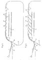
- biscuits 1 are delivered in a first number of columns 2 on a conveyor belt 3 in the conveying direction A of a redistribution device 4 from a continuous oven (not shown).
- the device 4 forms rows of biscuits 1 of the belt 3, a second number of second columns 5 on a second conveyor belt 6 running transversely to the belt 3 in the direction B from the belt 6, the biscuits 1 are transferred to a curved conveyor belt 7. From this belt 7, the biscuits 1 arrive in vibrating conveyor troughs 8, in which they are placed upright and are closed to one another on the flat side. Portioning devices 9 adjoin the channels 8, in which measured biscuit stacks are formed. These are finally packed in packaging machines 10.
- the device 4 is shown in plan view.
- the individual columns 2, 5 on the belts 3, 6 are separated from one another by guide plates 14, 15.
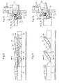
- the biscuits 1 are stowed on the belt 3, so that the biscuits 1 located on a transfer plate 16 form a row and are pushed against a rotating conveyor element 17.
- the conveyor member 17 consists of two lateral, circumferential, endless chains 18 and support plates 19 articulated on these chains 18 at regular intervals and stops 20 projecting outwards (FIGS. 3 to 8).
- the attacks 20 form one-piece, 90 ° angled extensions of the support plates 19.
- the plates 19 are connected to the chains 18 at their front end in the conveying direction A about horizontal axes 21 so as to be pivotable.
- each plate 19 has at least on one side a guide roller 22 (FIG. 9) which rotates on a guide rail.
- the chains 18 run obliquely upwards in a first section 26, and then horizontally across the conveyor belt 6 in a second section 27.
- the plates 19 are inclined upwards and, together with the stops 20 in longitudinal section according to FIG. 3, form a sawtooth shape.
- the plates 19 in the basic position (FIG. 3) are inclined slightly backwards downward, so that the biscuits 1 lying on them rest against the next stops 20.
- a number of plates 19 corresponding to the number of columns 5 to be formed can simultaneously be pivoted downward about their axes 21 (FIG. 4), so that the biscuits 1 lying on them slide onto the conveyor belt 6.
- the last section 28 of the belt 3 and the plate 16 are inclined slightly downwards, with an inclination corresponding approximately to the inclination of the stops 20 in the section 26 of the chains 18 5 to 8 is the transfer of the biscuits 1 to the conveyor 17 in section 26 in successive steps.
- the outwardly projecting width of the stops 20 is substantially less than half the width of the biscuits 1, so that the foremost biscuit 1 is only raised by the stop 20 at its front edge (FIG. 5).
- the subsequent biscuit 1 pushes the raised biscuit against the next support plate 19 (FIG. 6).
- the next stop 20 now lifts the front edge of the next biscuit 1 (FIGS. 7 and 8).
- the mechanism for lowering the plates 19 in section 27 is shown in Figs. 9-12.
- the guide rail 32 on which the rollers 22 roll has a plurality of inserts 33.
- the number of inserts 33 corresponds to the maximum number of columns 5 and their length corresponds to the distance between adjacent axes 21 or stops 20 from one another.
- At least some consecutive of the inserts 33 have depressions 34 that are aligned with the baffles 15.
- a second rail 35 is arranged next to the inserts 33.
- the rail 35 has a straight running surface 36. It is pivotally mounted on a lever 37 about a horizontal axis 38 on a support 39. A straight, horizontal guide rail 40 for the chain 18 is also fastened to the carrier 39 in the section 27.
- the lever 37 can be pivoted by a pneumatic cylinder 41 from the basic position shown in FIG. 10 into the second position according to FIG. 12.
- the running surface 36 is directly next to the inserts 33, so that the rollers 22 run with their outer halves on the second rail 35 and are held up when the depressions 34 are passed over.
- the rollers 22 In the second position of the rail 35 (FIG. 12), on the other hand, the rollers 22 only run on the rail 32 with their inserts 33 and pass through the depressions 34.
- the cycle frequency of the actuation of the cylinder 41 depends on the number of columns 5 n columns 5, the cylinder 41 is actuated in each case by a distance n times the length of the inserts 33 traveled by the conveying member 17.
- any number of columns 5 is formed from any number of columns 2, each of these second columns 5 biscuits from contains all first columns 2.
- the scattering of the net weights of the packaged stacks is kept low in the packaging machines 10, and the packaged biscuits have approximately the same average degree of browning in all packs.
- the biscuits 1 are handled gently by the device 4 described.
- the device 4 also works perfectly when the biscuits 1 are delivered on the conveyor belt 3 at irregular intervals.
- the number of second columns 5 can be selected as desired, in that the inserts 33 can be exchanged for other inserts with a straight running surface, that is to say without a depression 34.
- the inserts 33 are releasably attached to a console 42.
- the device 4 described it is also possible, as is indicated in FIG. 1, to divide the biscuits 1 from a feed conveyor belt 3 onto a plurality of packaging machines 10 and to adapt the division ratio during operation to the capacity of the packaging machines 10.
- one of several packaging machines 10 can be a reserve packaging machine that normally stands still and is only put into operation when another one fails.
- the rail 35 is divided into segments several times the length of the inserts 33, each segment having its own actuating cylinder 41.
- the cross conveyor belt 6 can be driven in both directions, e.g. in one direction the packaging machines 10, in the opposite direction e.g. a store or a reserve packaging machine can be loaded. If the transverse conveyor belt 6 stops, the biscuits 1 can be conveyed into a waste container or onto another storage belt transporting in the direction A with the conveying member 17.
Landscapes
- Engineering & Computer Science (AREA)
- Mechanical Engineering (AREA)
- Attitude Control For Articles On Conveyors (AREA)
- Framework For Endless Conveyors (AREA)
- Rollers For Roller Conveyors For Transfer (AREA)
- Packaging Frangible Articles (AREA)
- Intermediate Stations On Conveyors (AREA)
Claims (7)
- Dispositif pour la redistribution de produits alimentaires en forme de disque (1), en particulier de biscuits, délivrés à plat en un premier nombre de premières colonnes (2) sur un premier organe de transport (3), en un second nombre de secondes colonnes (5) de disques (1) sur un second organe de transport (6) qui les entraîne transversalement par rapport au premier organe de transport (3), dispositif dans lequel il est disposé, en aval du premier organe de transport (3), avec la même direction de transport (A), un organe transporteur (17) qui entraîne par rangées sur le second organe de transport (6) les disques (1) reçus du premier organe de transport (3), caractérisé en ce que l'organe transporteur (17) comprend deux éléments de traction (18) qui tournent parallèlement, en ce qu'il est disposé, entre les éléments de traction (18), des surfaces d'appui (19) pour les disques (1), ainsi que des butées (20) en saillie vers l'extérieur, à intervalles réguliers, pour les bords arrière des disques (1), en ce que les éléments de traction (18) présentent, au point de déversement du premier organe transporteur (3), un premier brin (26) qui s'étend obliquement vers le haut, de sorte qu'à ce niveau, les surfaces d'appui (19) soient inclinées obliquement vers le haut, en ce qu'un deuxième brin (27) des éléments de traction (18), faisant suite au premier brin, s'étend à peu près horizontalement et transversalement au-dessus du second organe de transport (6), en ce que, dans ce deuxième brin (27), plusieurs surfaces d'appui (19) successives, correspondant au second nombre de secondes colonnes (5), peuvent pivoter vers le bas à peu près en même temps, de sorte que les disques (1) qui reposent sur elles glissent sur le second organe de transport (6), et en ce que la hauteur des butées (20), en saillie sur les surfaces d'appui (19), est inférieure à la moitié de l'intervalle entre des butées (20) successives.
- Dispositif selon la revendication 1, caractérisé en ce que le nombre de surfaces d'appui (19) qui peuvent pivoter à peu près en même temps est réglable.
- Dispositif selon la revendication 1 ou 2, caractérisé en ce que les surfaces d'appui (19) sont réalisées sous forme de plaques qui sont articulées chacune sur les éléments de traction (18), par leur extrémité avant dans le sens du transport, de façon à pouvoir pivoter autour d'un axe horizontal de pivotement (21), et qui portent, d'un côté au moins, un galet de guidage (22) à distance de l'axe de pivotement (21).
- Dispositif selon la revendication 3, caractérisé en ce que, dans le deuxième brin (27) des éléments de traction (18), les galets de guidage (22) sont guidés sur un premier rail (32) qui présente plusieurs creux (34), la distance mutuelle des creux (34) correspondant à la distance mutuelle des butées (20), et en ce qu'à côté du premier rail (32), il est disposé un second rail rectiligne (35) qui peut être déplacé entre deux positions par un élément d'actionnement (41), de telle sorte que, dans la première position du second rail (35), les galets (22) roulent sur celui-ci et maintiennent en haut les surface d'appui (19) et que, dans la seconde position du second rail (35), ils roulent sur le premier rail (32) et qu'au passage dans les creux (34), les surfaces d'appui (19) soient inclinées.
- Dispositif selon la revendication 4, caractérisé en ce que le premier rail (32) comprend plusieurs segments partiels (33) qui contiennent chacun au moins un creux (34) et qui peuvent être échangés contre d'autres segments partiels (33) comportant moins de creux (34) ou dépourvus de ceux-ci.
- Dispositif selon l'un quelconque des revendications 1 à 5, caractérisé en ce que les butées (20) sont des prolongements coudés des surfaces d'appui en forme de plaque (19), d'une seule pièce avec celles-ci.
- Dispositif selon l'un quelconque des revendications 1 à 6, caractérisé en ce que chaque surface d'appui (19) forme un angle approximativement droit avec la butée (20) qui lui fait suite.
Applications Claiming Priority (2)
| Application Number | Priority Date | Filing Date | Title |
|---|---|---|---|
| CH1604/88 | 1988-04-29 | ||
| CH160488 | 1988-04-29 |
Publications (2)
| Publication Number | Publication Date |
|---|---|
| EP0340164A1 EP0340164A1 (fr) | 1989-11-02 |
| EP0340164B1 true EP0340164B1 (fr) | 1992-12-30 |
Family
ID=4214304
Family Applications (1)
| Application Number | Title | Priority Date | Filing Date |
|---|---|---|---|
| EP89810272A Expired - Lifetime EP0340164B1 (fr) | 1988-04-29 | 1989-04-10 | Dispositif de redistribution de disques alimentaires d'un premier sur un deuxième organe de transport |
Country Status (7)
| Country | Link |
|---|---|
| US (1) | US4940129A (fr) |
| EP (1) | EP0340164B1 (fr) |
| JP (1) | JP2704899B2 (fr) |
| AR (1) | AR246919A1 (fr) |
| BR (1) | BR8901982A (fr) |
| DE (1) | DE58903138D1 (fr) |
| ES (1) | ES2036369T3 (fr) |
Cited By (1)
| Publication number | Priority date | Publication date | Assignee | Title |
|---|---|---|---|---|
| KR20240025229A (ko) * | 2022-08-18 | 2024-02-27 | (주)지피엔 | 인쇄회로기판 이송 시스템 |
Families Citing this family (12)
| Publication number | Priority date | Publication date | Assignee | Title |
|---|---|---|---|---|
| US5287953A (en) * | 1992-02-20 | 1994-02-22 | Machine Builders And Design Inc. | Flip-slide apparatus |
| DE4210277C5 (de) * | 1992-03-28 | 2009-02-26 | Henkel Ag & Co. Kgaa | Kleb- und Dichtstoff und dessen Verwendung |
| JP3256751B2 (ja) * | 1993-05-06 | 2002-02-12 | 四国化工機株式会社 | 固形物の搬送装置 |
| FR2730711B1 (fr) * | 1995-02-21 | 1997-05-09 | Materiel Arboriculture | Dispositif d'alimentation d'une unite de tri de produits longiformes, tels que carottes, unite de tri comportant ce dernier, et dispositif de distribution et calibreuse de cette unite de tri. |
| EP2178777A4 (fr) * | 2007-07-17 | 2013-05-29 | Food Processing Systems | Système d'orientation et d'accumulation d' ufs à convoyeurs de marche avant et arrière interconnectés pour empêcher le débordement/la superposition d' ufs avant leur sortie en rangées individuelles sur des barres à bobines |
| US9272421B2 (en) * | 2013-01-07 | 2016-03-01 | Milos Misha Subotincic | Visually controlled end effector |
| CN103600869B (zh) * | 2013-11-19 | 2015-07-15 | 浙江理工大学 | 阶梯式饼干并道装置 |
| CN109834065B (zh) * | 2019-03-07 | 2023-11-24 | 江苏锦明工业机器人自动化有限公司 | 一种用于高速分拣的y型斜口分拣机 |
| CN110255114A (zh) * | 2019-06-25 | 2019-09-20 | 苏州市运泰利自动化设备有限公司 | 锂电池料盘输送装置 |
| CN112570956B (zh) * | 2020-11-30 | 2022-09-16 | 哈尔滨威星动力电源科技开发有限责任公司 | 一种防撞式锂电池组焊接装置 |
| CN115739649B (zh) * | 2022-11-11 | 2025-04-18 | 湖南拙燕仓物流有限公司 | 一种智能仓储用物料分拣理货装置 |
| US12178213B2 (en) * | 2022-12-16 | 2024-12-31 | Lawrence Equipment, Inc. | Multi-conveyor transfer system |
Family Cites Families (15)
| Publication number | Priority date | Publication date | Assignee | Title |
|---|---|---|---|---|
| US1343184A (en) * | 1918-01-11 | 1920-06-08 | Joseph Baker S Ltd | Dough-feeding device |
| US2704177A (en) * | 1950-02-17 | 1955-03-15 | Thompson Machine Company | Roll panning machine |
| US2806579A (en) * | 1951-12-21 | 1957-09-17 | Union Machinery Company | Conveyor loading mechanism |
| CH400892A (de) * | 1963-05-08 | 1965-10-15 | Sig Schweiz Industrieges | Vorrichtung zum Gruppieren und Zuführen von Gegenständen |
| DE1188013B (de) * | 1964-07-18 | 1965-03-04 | Werner & Pfleiderer | Vorrichtung zum UEbertragen von Teigstuecken |
| DE2249383C3 (de) * | 1972-10-09 | 1985-08-01 | Kemper, Kate, Küsnacht, Zürich | Teigbearbeitungsanlage |
| JPS51116144A (en) * | 1975-04-04 | 1976-10-13 | Mitsubishi Electric Corp | Device for controlling rotation speed of members under welding |
| JPS5654047A (en) * | 1979-10-08 | 1981-05-13 | Nec Corp | Compound semiconductor device |
| JPS57152376A (en) * | 1981-03-13 | 1982-09-20 | Shin Meiwa Ind Co Ltd | Fillet copying welding machine |
| SE428676B (sv) * | 1981-04-16 | 1983-07-18 | Spooner Ind Ltd | Avlastningsanordning vid transportorer |
| US4410079A (en) * | 1981-11-19 | 1983-10-18 | Otto Niederer Sons, Inc. | Egg conveyor turning apparatus |
| CH657829A5 (de) * | 1982-12-17 | 1986-09-30 | Sig Schweiz Industrieges | Vorrichtung zum umordnen von scheibenfoermigen gegenstaenden, z.b. biskuits. |
| JPS6064780A (ja) * | 1983-09-17 | 1985-04-13 | Nakajima:Kk | 溶接用電気接点支持装置 |
| JPS6072687A (ja) * | 1983-09-26 | 1985-04-24 | Daiwa Kogyo Kk | 角形形鋼の製造方法 |
| DE3601904A1 (de) * | 1986-01-23 | 1987-07-30 | Werner & Pfleiderer | Verfahren und vorrichtung zum umsetzen von gebaeckstuecken |
-
1989
- 1989-03-03 AR AR89313328A patent/AR246919A1/es active
- 1989-04-07 US US07/334,542 patent/US4940129A/en not_active Expired - Fee Related
- 1989-04-10 DE DE8989810272T patent/DE58903138D1/de not_active Expired - Fee Related
- 1989-04-10 ES ES198989810272T patent/ES2036369T3/es not_active Expired - Lifetime
- 1989-04-10 EP EP89810272A patent/EP0340164B1/fr not_active Expired - Lifetime
- 1989-04-19 JP JP1097660A patent/JP2704899B2/ja not_active Expired - Fee Related
- 1989-04-27 BR BR898901982A patent/BR8901982A/pt not_active IP Right Cessation
Cited By (1)
| Publication number | Priority date | Publication date | Assignee | Title |
|---|---|---|---|---|
| KR20240025229A (ko) * | 2022-08-18 | 2024-02-27 | (주)지피엔 | 인쇄회로기판 이송 시스템 |
Also Published As
| Publication number | Publication date |
|---|---|
| JP2704899B2 (ja) | 1998-01-26 |
| AR246919A1 (es) | 1994-10-31 |
| BR8901982A (pt) | 1989-12-05 |
| EP0340164A1 (fr) | 1989-11-02 |
| ES2036369T3 (es) | 1993-05-16 |
| JPH01299114A (ja) | 1989-12-01 |
| DE58903138D1 (de) | 1993-02-11 |
| US4940129A (en) | 1990-07-10 |
Similar Documents
| Publication | Publication Date | Title |
|---|---|---|
| EP0340164B1 (fr) | Dispositif de redistribution de disques alimentaires d'un premier sur un deuxième organe de transport | |
| DE4303413A1 (de) | Beschickungsvorrichtung für eine Palettiervorrichtung | |
| EP0300958B1 (fr) | Dispositif de transport pour des produits en position verticale en particulier des biscuits | |
| DE2415376A1 (de) | Vorrichtung zum verpacken von eiern in behaelter | |
| CH669370A5 (fr) | ||
| DE69210703T2 (de) | Fluidum benutzende Vorrichtung zum Durchführen einer verschachtelten Ausrichtung von Gegenständen mit rundem Querschnitt | |
| EP0630815A1 (fr) | Installation pour séparer, transférer et grouper des objets aplatis | |
| DE102021116619A1 (de) | Einlege-Zufuhreinheit sowie Verfahren für ihren Betrieb | |
| EP0684196B1 (fr) | Dispositif de groupage, de transport et de stockage | |
| DE69607698T2 (de) | Vorrichtung zum Be- und/oder Entladen von einem Behälter mit Stapeln von Packungen, insbesondere Eierkartons | |
| DE3803377A1 (de) | Transporteinrichtung fuer gruppen von nahrungsmittelscheiben, insbesondere biscuits | |
| DE102015113401A1 (de) | Ausgabeeinheit für Backwaren | |
| CH681590A5 (fr) | ||
| DE2900139C3 (de) | Walzenförderer | |
| DE1729441C3 (de) | Trocknungskammer mit stapelbaren Gutträgern zum Trocknen von langgestrecktem, geschichtetem Gut aus Holz | |
| EP0888829B1 (fr) | Dispositif de tri d'articles, en particulier de bois débité | |
| DE3417157C2 (de) | Vorrichtung zum Umkippen und Anordnen ankommender Kartons in mehreren Reihen auf einen Förderer | |
| DE4338839C1 (de) | Vorrichtung zum Vereinzeln von quaderförmigen Stäbchen aus tiefgefrorenem Lebensmittel | |
| DE1291682B (de) | Einrichtung zum geordneten Foerdern von Eiern | |
| EP3766812B1 (fr) | Machine de dépalletisation pourvu de dispositif de transfert et de distribution de charge dépalletisée | |
| DE3247429C2 (fr) | ||
| DE2137770C3 (de) | Teigs tückbearbeitungseinrichtung | |
| DE10154437A1 (de) | Vorrichtung zum Sortieren und Stapeln von Stückgütern | |
| DE60001514T2 (de) | Vorrichtung zum Sortieren von Produkten,insbesondere zum gruppenweisen Anordnen | |
| DE69109967T2 (de) | Mechanisches Fördersystem zum Drehen und Aufteilen einer Reihe von Packungen. |
Legal Events
| Date | Code | Title | Description |
|---|---|---|---|
| PUAI | Public reference made under article 153(3) epc to a published international application that has entered the european phase |
Free format text: ORIGINAL CODE: 0009012 |
|
| AK | Designated contracting states |
Kind code of ref document: A1 Designated state(s): CH DE ES FR GB IT LI NL |
|
| 17P | Request for examination filed |
Effective date: 19891117 |
|
| 17Q | First examination report despatched |
Effective date: 19920109 |
|
| GRAA | (expected) grant |
Free format text: ORIGINAL CODE: 0009210 |
|
| AK | Designated contracting states |
Kind code of ref document: B1 Designated state(s): CH DE ES FR GB IT LI NL |
|
| ITF | It: translation for a ep patent filed | ||
| ET | Fr: translation filed | ||
| REF | Corresponds to: |
Ref document number: 58903138 Country of ref document: DE Date of ref document: 19930211 |
|
| GBT | Gb: translation of ep patent filed (gb section 77(6)(a)/1977) |
Effective date: 19930120 |
|
| REG | Reference to a national code |
Ref country code: ES Ref legal event code: FG2A Ref document number: 2036369 Country of ref document: ES Kind code of ref document: T3 |
|
| PLBE | No opposition filed within time limit |
Free format text: ORIGINAL CODE: 0009261 |
|
| STAA | Information on the status of an ep patent application or granted ep patent |
Free format text: STATUS: NO OPPOSITION FILED WITHIN TIME LIMIT |
|
| 26N | No opposition filed | ||
| PGFP | Annual fee paid to national office [announced via postgrant information from national office to epo] |
Ref country code: CH Payment date: 19960312 Year of fee payment: 8 |
|
| PG25 | Lapsed in a contracting state [announced via postgrant information from national office to epo] |
Ref country code: LI Free format text: LAPSE BECAUSE OF NON-PAYMENT OF DUE FEES Effective date: 19970430 Ref country code: CH Free format text: LAPSE BECAUSE OF NON-PAYMENT OF DUE FEES Effective date: 19970430 |
|
| REG | Reference to a national code |
Ref country code: CH Ref legal event code: PL |
|
| PGFP | Annual fee paid to national office [announced via postgrant information from national office to epo] |
Ref country code: FR Payment date: 19980312 Year of fee payment: 10 |
|
| PGFP | Annual fee paid to national office [announced via postgrant information from national office to epo] |
Ref country code: ES Payment date: 19980415 Year of fee payment: 10 |
|
| PGFP | Annual fee paid to national office [announced via postgrant information from national office to epo] |
Ref country code: NL Payment date: 19980430 Year of fee payment: 10 |
|
| PG25 | Lapsed in a contracting state [announced via postgrant information from national office to epo] |
Ref country code: ES Free format text: LAPSE BECAUSE OF NON-PAYMENT OF DUE FEES Effective date: 19990412 |
|
| PG25 | Lapsed in a contracting state [announced via postgrant information from national office to epo] |
Ref country code: NL Free format text: LAPSE BECAUSE OF NON-PAYMENT OF DUE FEES Effective date: 19991101 |
|
| PG25 | Lapsed in a contracting state [announced via postgrant information from national office to epo] |
Ref country code: FR Free format text: LAPSE BECAUSE OF NON-PAYMENT OF DUE FEES Effective date: 19991231 |
|
| NLV4 | Nl: lapsed or anulled due to non-payment of the annual fee |
Effective date: 19991101 |
|
| REG | Reference to a national code |
Ref country code: FR Ref legal event code: ST |
|
| PGFP | Annual fee paid to national office [announced via postgrant information from national office to epo] |
Ref country code: DE Payment date: 20000324 Year of fee payment: 12 |
|
| REG | Reference to a national code |
Ref country code: ES Ref legal event code: FD2A Effective date: 20010503 |
|
| REG | Reference to a national code |
Ref country code: GB Ref legal event code: IF02 |
|
| PG25 | Lapsed in a contracting state [announced via postgrant information from national office to epo] |
Ref country code: DE Free format text: LAPSE BECAUSE OF NON-PAYMENT OF DUE FEES Effective date: 20020201 |
|
| PGFP | Annual fee paid to national office [announced via postgrant information from national office to epo] |
Ref country code: IT Payment date: 20080428 Year of fee payment: 20 |
|
| PGFP | Annual fee paid to national office [announced via postgrant information from national office to epo] |
Ref country code: GB Payment date: 20080423 Year of fee payment: 20 |
|
| REG | Reference to a national code |
Ref country code: GB Ref legal event code: PE20 Expiry date: 20090409 |
|
| PG25 | Lapsed in a contracting state [announced via postgrant information from national office to epo] |
Ref country code: GB Free format text: LAPSE BECAUSE OF EXPIRATION OF PROTECTION Effective date: 20090409 |