EP0338647A1 - Düngerstreuer - Google Patents
Düngerstreuer Download PDFInfo
- Publication number
- EP0338647A1 EP0338647A1 EP89200996A EP89200996A EP0338647A1 EP 0338647 A1 EP0338647 A1 EP 0338647A1 EP 89200996 A EP89200996 A EP 89200996A EP 89200996 A EP89200996 A EP 89200996A EP 0338647 A1 EP0338647 A1 EP 0338647A1
- Authority
- EP
- European Patent Office
- Prior art keywords
- implement
- hopper
- guide channels
- members
- spreading
- Prior art date
- Legal status (The legal status is an assumption and is not a legal conclusion. Google has not performed a legal analysis and makes no representation as to the accuracy of the status listed.)
- Granted
Links
Images

Classifications
-
- F—MECHANICAL ENGINEERING; LIGHTING; HEATING; WEAPONS; BLASTING
- F16—ENGINEERING ELEMENTS AND UNITS; GENERAL MEASURES FOR PRODUCING AND MAINTAINING EFFECTIVE FUNCTIONING OF MACHINES OR INSTALLATIONS; THERMAL INSULATION IN GENERAL
- F16L—PIPES; JOINTS OR FITTINGS FOR PIPES; SUPPORTS FOR PIPES, CABLES OR PROTECTIVE TUBING; MEANS FOR THERMAL INSULATION IN GENERAL
- F16L5/00—Devices for use where pipes, cables or protective tubing pass through walls or partitions
- F16L5/02—Sealing
- F16L5/12—Sealing the pipe being cut in two pieces
-
- A—HUMAN NECESSITIES
- A01—AGRICULTURE; FORESTRY; ANIMAL HUSBANDRY; HUNTING; TRAPPING; FISHING
- A01C—PLANTING; SOWING; FERTILISING
- A01C7/00—Sowing
- A01C7/08—Broadcast seeders; Seeders depositing seeds in rows
- A01C7/081—Seeders depositing seeds in rows using pneumatic means
Definitions
- the invention relates to an implement for spreading material, in particular a pneumatic seed drill, which implement comprises a hopper for storing the material and a distribution member which extends at least partly into said hopper, in which implement, during operation, the material is conveyed via the distribution member and via guide channels extending from said distribution member outwardly through the hopper wall to spreading members arranged thereto.
- the implement it is advantageous that the section consisting of the hopper, the distribution member arranged therein, and the inner portions of the guide channel can be pre-fabricated as an integral whole and be mounted as such to the implement.
- the hopper it is advantageous when the hopper can be attached to the frame of the implement in a simple manner by means of detachable connection members.
- the coupling member is provided with a supporting edge located against the inner side of the hopper wall and with a groove located outside the hopper wall, which groove accommodates a locking ring against the outer side of the hopper wall.
- the outer portion of a guide channel is connected to the coupling member in such a manner that it is easily detachable therefrom.
- the assembly of the outer portions of the guide channels together with the spreading members can be detached from the hopper and the frame and be attached again thereto in a different manner, the arrangement being such that the implement occupies less space when it is stored for use at a later instant.
- the assembly of spreading members and outer portions of the guide channels can be connected again to the frame in a simple way when the respective coupling members and outer portions of the guide channels to be interconnected are provided with markings so as to allow of an easy and fast interconnection.
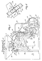
- the implement in accordance with the invention shown in the drawings as a pneumatic seed drill, comprises a frame 1 which is provided with coupling members constituted by coupling pins 2 and a coupling strip 3.
- the implement can be coupled to the lifting hitch of a tractor or to a different implement, e.g. a soil cultivating implement.
- the frame 1 is provided with supporting wheels 4.
- the seed drill includes a hopper 6 for the material to be sown as well as spreading members in the form of two rows of seed coulters 7 and 8, of which two rows the row of seed coulters 8 is located behind the row of seed coulters 7, taken in the direction of operative travel 9 of the seed drill. Behind the seed coulters 7 and 8 there are arranged tines 10 for covering the furrows made by the coulters.
- the seed coulters 7 and 8 are attached to a supporting beam 13 via tubular carrier arms 11 and 12, respectively, so as to be movable in height.
- the supporting beam 13 is provided with connecting lugs 14, by means of which the beam is bolted to frame arms 16 by bolts 15.
- the upper ends 17 and 18 of the carrier arms 11 and 12 are connected to a distribution member 20 via flexible distribution tubes 19.
- the distribution member 20 comprises a rise pipe 21 which partly extends from bottom to top in the vertical direction through the hopper 6 and at the upper side is provided with a distribution box 22.
- the lower end of the rise pipe 21 links up with a doser device 25 which is connected to a (non-shown) discharge aperture in the bottom side of the hopper 6.
- the doser device 25 is coupled to a stepper wheel 27 which bears on the soil during operation of the implement.
- the doser device 25 is connected to a fan 29.
- the distribution tubes 19 extend between the distribution box 22 and the tubular carrier arms 11 and 12. Together with the hollow tubular carrier arms 11 and 12, the distribution tubes 19 constitute guide channels for conveying material from the distribution box 22 to the seed coulters 7 and 8.
- Each distribution tube 19 comprises two flexible portions 31 and 32 which are intercoupled by a coupling member 33.
- the coupling members 33 are arranged in the wall of the hopper 6, as has been shown in Figure 2 for one coupling member 33.
- the portions 31 extend between the distribution box 22 and the relevant coupling member in the hopper wall, thereby constituting the inner portions 31 located substantially inside the hopper.
- the portions 32 extend between the coupling members 33 and the relevant tubular carrier arms 11 and 12, thereby constituting the outer portions 32 located outside the hopper.
- the coupling members 33 are substantially identical to the inner portions 31 and the outer portions 32 which, in this embodiment, are of a circular cross-section, while the coupling member 33 is a round tubular member.
- the coupling member 33 has a coupling end 34 which extends into the hopper and a coupling end 35 which extends outside of it.
- the inner portions 31 and the outer portions 32 of the distribution tubes 19 are connected to the coupling ends 34 and 35, respectively.
- the inner portions 31, only two of which have been shown in Figure 1, further connect to tubular connection members 36 of the distribution box 22.
- Each of the coupling members 33 includes a supporting ring 39 located against the inner side of the hopper wall.
- a thicker coupling member portion 41 extending through one of the apertures 44 in the hopper wall 40 there is formed a groove 42 ( Figure 2).
- the groove 42 accommodates a locking ring 43, or a connecting ring of an other type, located against the outer side of the hopper wall 40.
- Figure 1 shows only the apertures 44 through which the relevant coupling members 33 can be inserted.
- the hopper 6 is fitted with supports 46 which are bolted to the carrier arms 48 of the frame 1 by means of detachable bolt connections 47.
- the supporting wheels 4 are applied to carrier arms 50 of the frame 1.
- track looseners 51 are fitted to the carrier arms 50 by means of strips 52. Taken in the direction of operative travel 9 of the machine, the track looseners 51 are located behind the supporting wheels 4.
- the machine At its rear side, the machine is provided with a foot support 53 which is connected to the frame by means of a carrier bracket 54.
- Figure 1 shows the machine in an idle position. In this position, the implement bears on the supporting wheels 4 and on supporting legs 56 fitted to the frame. These supporting legs 56 are connected detachably to the frame by means of locking pins 57.
- the machine is coupled to the lifting hitch of a tractor or of a suchlike vehicle or to an other type of implement which, for example, is coupled already to a tractor.
- the machine Prior to being used, the machine can be coupled to the lifting hitch of a tractor or to the connection members of an other implement by means of the coupling pins 2 and the coupling strip 3.
- the machine is particularly suitable for connection to a soil cultivating machine, e.g. an implement for preparing a seed bed.
- the seed drill can then be connected in such a manner to the soil cultivating machine by means of the coupling pins 2 and the coupling strip 3 that this soil cultivating machine is positioned, at least for a large part, under the hopper 6.
- the seed drill When the seed drill is used in combination with a soil cultivating machine, it is advantageous to arrange them in such a manner relative to each other that the hopper is located at least substantially over the soil cultivating machine.
- the total weight of the seed drill - soil cultivating machine combination is located as closely as possible to the vehicle, e.g. a tractor hauling the combination.
- the soil cultivating machine - seed drill combina tion can be coupled to the lifting hitch of the tractor. So as to permit of arranging the hopper 6 over a soil cultivating machine, this hopper is in a comparatively high position relative to the seed coulters 7 and 8 and the supporting wheels 4.
- the space for accommodating the soil cultivating machine under the hopper 6 can be obtained in particular when the distance 58 between a vertical plane 59 containing the centre line of the supporting beam 13 and a vertical plane 60 containing the centre lines of the hopper 6 and of the rise tube 21 of the distribution member 20 is comparatively large. Then, the total length 61 through which the machine extends parallel to the direction of operative travel 9 is also comparatively great. In this situation, the seed coulters 7 and 8 are positioned fully behind the hopper 6, taken in the direction of operative travel 9, as is also the stepper wheel 27. In this construction, in order to avoid the necessity of positioning the hopper 6 excessively high, the fan 29 is positioned substantially behind the hopper.
- the supporting wheels 4 are also in a position which, relative to the direction of operative travel 9, is located substantially further towards the rear than the rear side of the hopper 6.
- the large length 61 is a disadvantage as it then occupies a great deal of floor space.
- the length of the machine can be reduced significantly prior to transport or storage.
- the assembly of the two rows of seed coulters 7 and 8, together with the supporting beam 13 to which they are connected can be detached from the frame by removing the bolts 15.
- the assembly of the two rows of seed coulters 7 and 8 and the supporting beam 13 can then be rotated through 180° and be bolted again to the frame arms 16 by means of the bolts 15, as has been illustrated in Figure 4.
- the machine can easily be supported by the ground wheels 4 and the supporting legs 56.
- the rows of seed coulters 7 and 8 are then in a position in which they are protected to some extent between the ground wheels 4 and the supporting legs 56, said legs as well as said ground wheels 4 being positioned on either side of the implement and spaced apart by distances which are at least approximately equal to or slightly in excess of the length of the rows of seed coulters 7 and 8.
- the stepper wheel 27 together with a chain drive 63 coupled thereto and belonging to the transmission member 26, and a drive shaft 64 can be removed from the machine. Since only one stepper wheel 27 with relevant transmission members 63 and 64 is present, a removal of these components from the implement will not offer a serious objection.
- the foot support 53 and the bracket 54 as well as the track loosener 51 and the strip 52 can be removed from the implement.
- the machine then has a length 62 ( Figure 4) which is considerably less, in this embodiment approximately 20%, than the length 61.
- the removed components, such as the track looseners 51, the stepper wheel 27 and the foot support 53, may be stored in the hopper 6.
- the distribution tubes 19 are divided into an inner portion 31 and an outer portion 32.
- the distribution tubes 19 are divided into two groups, each of which extends through a group of apertures 44 in opposite sidewalls 40 of the hopper 6.
- the outer portions 32 of the distribution tubes 19 are divided in two groups, one group being contiguous at one side of the hopper 6 and the other group at the other side to coupling members 33 arranged in opposite sidewalls of the hopper.
- the outer portions 32 can be disposed easily detachably over the connecting ends 35, or be removed therefrom.
- the outer portions 32 are detached from the connecting ends 35, whereafter the assembly formed by the supporting beam 13, the rows of seed coulters 7 and 8 and the outer portions 32 can be connected again to the frame arms 16 of the frame in a position which is rotated through 180° relative to Figure 1.
- the outer portions 32 can be connected again to the connecting ends 35 after the rows of seed coulters 7 and 8 together with the supporting beam 13 have been rotated back.
- the position of the seed coulters 7 and 8 together with the beam 13 and the outer portions 32 as shown in Figure 1 constitutes a first position for the assembly.
- Figure 4 shows a second position therefor.
- the relevant connecting ends 35 and the ends of the relevant outer portions 32 fitting thereon have been marked such, e.g. by numbering them, that the correct outer portions can be connected again to the correct connecting ends 35.
- the hopper is connectable to the carrier arms 48 of the frame 1 by means of the bolts 47.
- This connection whereby the hopper together with the distribution member 20 and the inner portions 31 can be removed as a whole from the frame by releasing the bolts 47, can also be of importance for maintenance and repair of the machine.
Landscapes
- Life Sciences & Earth Sciences (AREA)
- Soil Sciences (AREA)
- Engineering & Computer Science (AREA)
- General Engineering & Computer Science (AREA)
- Environmental Sciences (AREA)
- Mechanical Engineering (AREA)
- Sowing (AREA)
- Fertilizing (AREA)
Applications Claiming Priority (2)
| Application Number | Priority Date | Filing Date | Title |
|---|---|---|---|
| NL8801038 | 1988-04-21 | ||
| NL8801038A NL8801038A (nl) | 1988-04-21 | 1988-04-21 | Inrichting voor het verspreiden van materiaal. |
Publications (2)
| Publication Number | Publication Date |
|---|---|
| EP0338647A1 true EP0338647A1 (de) | 1989-10-25 |
| EP0338647B1 EP0338647B1 (de) | 1994-06-22 |
Family
ID=19852179
Family Applications (1)
| Application Number | Title | Priority Date | Filing Date |
|---|---|---|---|
| EP19890200996 Expired - Lifetime EP0338647B1 (de) | 1988-04-21 | 1989-04-19 | Düngerstreuer |
Country Status (3)
| Country | Link |
|---|---|
| EP (1) | EP0338647B1 (de) |
| DE (1) | DE68916314T2 (de) |
| NL (1) | NL8801038A (de) |
Cited By (7)
| Publication number | Priority date | Publication date | Assignee | Title |
|---|---|---|---|---|
| FR2691039A1 (fr) * | 1992-05-16 | 1993-11-19 | Rauch Landmaschfab Gmbh | Semoir à réservoir mobile. |
| DE4238019A1 (de) * | 1992-11-11 | 1994-05-19 | Rauch Landmaschfab Gmbh | Pneumatische Sämaschine und landwirtschaftliche Gerätekombination mit einer solchen |
| US5379706A (en) * | 1993-04-07 | 1995-01-10 | Agco Corporation | Seed distribution system for planters and drills |
| DE4434963A1 (de) * | 1993-10-22 | 1995-04-27 | Rauch Landmaschfab Gmbh | Sämaschine |
| DE19620830A1 (de) * | 1995-06-17 | 1996-12-19 | Rauch Landmaschfab Gmbh | Sämaschine mit einem trichterförmigen Saatgut-Behälter |
| EP0758523A1 (de) * | 1995-08-16 | 1997-02-19 | Amazonen-Werke H. Dreyer GmbH & Co. KG | Pneumatische Verteilmaschine |
| US6772702B2 (en) * | 2002-03-21 | 2004-08-10 | Case Corporation | Lockdown and support structure for agricultural particulate tank |
Citations (5)
| Publication number | Priority date | Publication date | Assignee | Title |
|---|---|---|---|---|
| US3812910A (en) * | 1972-11-20 | 1974-05-28 | W Wellstein | Positive seal pitless well adapter |
| FR2270509A1 (en) * | 1974-05-06 | 1975-12-05 | Patzner Kg | Jointing of tubes through thin partitions - with screwed joint which clamps assembly in partition orifice |
| EP0037337A2 (de) * | 1980-03-31 | 1981-10-07 | Société SOGEFINA Société de Gestion Financière Armoricaine (Société Anonyme) | Verteilervorrichtung für Präzisionssämaschine |
| EP0096017A2 (de) * | 1982-06-02 | 1983-12-07 | Usines & Fonderies Arthur Martin, S.A. | Obenbeschickbare Waschmaschine |
| EP0255155A2 (de) * | 1986-06-13 | 1988-02-03 | C. van der Lely N.V. | Sämaschine |
-
1988
- 1988-04-21 NL NL8801038A patent/NL8801038A/nl not_active Application Discontinuation
-
1989
- 1989-04-19 DE DE1989616314 patent/DE68916314T2/de not_active Expired - Fee Related
- 1989-04-19 EP EP19890200996 patent/EP0338647B1/de not_active Expired - Lifetime
Patent Citations (5)
| Publication number | Priority date | Publication date | Assignee | Title |
|---|---|---|---|---|
| US3812910A (en) * | 1972-11-20 | 1974-05-28 | W Wellstein | Positive seal pitless well adapter |
| FR2270509A1 (en) * | 1974-05-06 | 1975-12-05 | Patzner Kg | Jointing of tubes through thin partitions - with screwed joint which clamps assembly in partition orifice |
| EP0037337A2 (de) * | 1980-03-31 | 1981-10-07 | Société SOGEFINA Société de Gestion Financière Armoricaine (Société Anonyme) | Verteilervorrichtung für Präzisionssämaschine |
| EP0096017A2 (de) * | 1982-06-02 | 1983-12-07 | Usines & Fonderies Arthur Martin, S.A. | Obenbeschickbare Waschmaschine |
| EP0255155A2 (de) * | 1986-06-13 | 1988-02-03 | C. van der Lely N.V. | Sämaschine |
Cited By (11)
| Publication number | Priority date | Publication date | Assignee | Title |
|---|---|---|---|---|
| FR2691039A1 (fr) * | 1992-05-16 | 1993-11-19 | Rauch Landmaschfab Gmbh | Semoir à réservoir mobile. |
| DE4315343C2 (de) * | 1992-05-16 | 2003-04-30 | Rauch Landmaschfab Gmbh | Sämaschine |
| DE4238019A1 (de) * | 1992-11-11 | 1994-05-19 | Rauch Landmaschfab Gmbh | Pneumatische Sämaschine und landwirtschaftliche Gerätekombination mit einer solchen |
| DE4238019C2 (de) * | 1992-11-11 | 1998-11-12 | Rauch Landmaschfab Gmbh | Landwirtschaftliche Gerätekombination mit einer pneumatischen Sämaschine und einer Bodenbearbeitungsmaschine |
| US5379706A (en) * | 1993-04-07 | 1995-01-10 | Agco Corporation | Seed distribution system for planters and drills |
| DE4434963A1 (de) * | 1993-10-22 | 1995-04-27 | Rauch Landmaschfab Gmbh | Sämaschine |
| DE4434963C2 (de) * | 1993-10-22 | 1999-11-04 | Rauch Landmaschfab Gmbh | Sämaschine |
| DE19620830A1 (de) * | 1995-06-17 | 1996-12-19 | Rauch Landmaschfab Gmbh | Sämaschine mit einem trichterförmigen Saatgut-Behälter |
| DE19620830C2 (de) * | 1995-06-17 | 2002-05-16 | Rauch Landmaschfab Gmbh | Sämaschine mit einem trichterförmigen Saatgut-Behälter |
| EP0758523A1 (de) * | 1995-08-16 | 1997-02-19 | Amazonen-Werke H. Dreyer GmbH & Co. KG | Pneumatische Verteilmaschine |
| US6772702B2 (en) * | 2002-03-21 | 2004-08-10 | Case Corporation | Lockdown and support structure for agricultural particulate tank |
Also Published As
| Publication number | Publication date |
|---|---|
| EP0338647B1 (de) | 1994-06-22 |
| DE68916314T2 (de) | 1995-01-26 |
| NL8801038A (nl) | 1989-11-16 |
| DE68916314D1 (de) | 1994-07-28 |
Similar Documents
| Publication | Publication Date | Title |
|---|---|---|
| US4539921A (en) | Drill frame construction | |
| EP0338647A1 (de) | Düngerstreuer | |
| EP0513939B1 (de) | Bodenbearbeitungsgerät | |
| EP0506210B1 (de) | Streuer | |
| EP0269149B1 (de) | Klappgestänge für Sämaschine | |
| WO1996009950A1 (en) | Agricultural machine and implements therefor | |
| EP0335455B1 (de) | Kombinierte Drill- und Bodenbearbeitungsmaschine | |
| EP0059520B2 (de) | Bodenbearbeitungsgeräte | |
| EP0687406B1 (de) | Sämaschine | |
| US2532076A (en) | Adjustable axle construction for potato planters | |
| US6843186B2 (en) | Narrow row spacing planter | |
| CN112272978A (zh) | 一种农业种植用播种器 | |
| KR102111298B1 (ko) | 마늘 파종기 | |
| JP3259171B2 (ja) | 田植機 | |
| JP3572468B2 (ja) | 移植機 | |
| CN210986999U (zh) | 一种车载式播种机 | |
| CN216134820U (zh) | 一种用于等距离精准下种的播种机 | |
| EP0459175A1 (de) | Landwirtschaftliche Gerätekombination | |
| JP4058781B2 (ja) | 載置装置 | |
| JPH0458808A (ja) | 乗用野菜移植機 | |
| CN209806408U (zh) | 播种机 | |
| CN114532022A (zh) | 插秧机 | |
| CN114532019A (zh) | 插秧机 | |
| US11083123B2 (en) | Multi-purpose agricultural implement | |
| CN114532021A (zh) | 育苗箱和插秧机 |
Legal Events
| Date | Code | Title | Description |
|---|---|---|---|
| PUAI | Public reference made under article 153(3) epc to a published international application that has entered the european phase |
Free format text: ORIGINAL CODE: 0009012 |
|
| AK | Designated contracting states |
Kind code of ref document: A1 Designated state(s): DE FR GB NL |
|
| 17P | Request for examination filed |
Effective date: 19900409 |
|
| 17Q | First examination report despatched |
Effective date: 19910211 |
|
| GRAA | (expected) grant |
Free format text: ORIGINAL CODE: 0009210 |
|
| AK | Designated contracting states |
Kind code of ref document: B1 Designated state(s): DE FR GB NL |
|
| REF | Corresponds to: |
Ref document number: 68916314 Country of ref document: DE Date of ref document: 19940728 |
|
| ET | Fr: translation filed | ||
| PLBE | No opposition filed within time limit |
Free format text: ORIGINAL CODE: 0009261 |
|
| STAA | Information on the status of an ep patent application or granted ep patent |
Free format text: STATUS: NO OPPOSITION FILED WITHIN TIME LIMIT |
|
| 26N | No opposition filed | ||
| REG | Reference to a national code |
Ref country code: GB Ref legal event code: IF02 |
|
| PGFP | Annual fee paid to national office [announced via postgrant information from national office to epo] |
Ref country code: NL Payment date: 20020329 Year of fee payment: 14 |
|
| PGFP | Annual fee paid to national office [announced via postgrant information from national office to epo] |
Ref country code: FR Payment date: 20020401 Year of fee payment: 14 |
|
| PGFP | Annual fee paid to national office [announced via postgrant information from national office to epo] |
Ref country code: GB Payment date: 20020416 Year of fee payment: 14 |
|
| PGFP | Annual fee paid to national office [announced via postgrant information from national office to epo] |
Ref country code: DE Payment date: 20020418 Year of fee payment: 14 |
|
| PG25 | Lapsed in a contracting state [announced via postgrant information from national office to epo] |
Ref country code: GB Free format text: LAPSE BECAUSE OF NON-PAYMENT OF DUE FEES Effective date: 20030419 |
|
| PG25 | Lapsed in a contracting state [announced via postgrant information from national office to epo] |
Ref country code: NL Free format text: LAPSE BECAUSE OF NON-PAYMENT OF DUE FEES Effective date: 20031101 Ref country code: DE Free format text: LAPSE BECAUSE OF NON-PAYMENT OF DUE FEES Effective date: 20031101 |
|
| NLV4 | Nl: lapsed or anulled due to non-payment of the annual fee |
Effective date: 20031101 |
|
| GBPC | Gb: european patent ceased through non-payment of renewal fee |
Effective date: 20030419 |
|
| PG25 | Lapsed in a contracting state [announced via postgrant information from national office to epo] |
Ref country code: FR Free format text: LAPSE BECAUSE OF NON-PAYMENT OF DUE FEES Effective date: 20031231 |
|
| REG | Reference to a national code |
Ref country code: FR Ref legal event code: ST |