EP0037337A2 - Verteilervorrichtung für Präzisionssämaschine - Google Patents
Verteilervorrichtung für Präzisionssämaschine Download PDFInfo
- Publication number
- EP0037337A2 EP0037337A2 EP81400498A EP81400498A EP0037337A2 EP 0037337 A2 EP0037337 A2 EP 0037337A2 EP 81400498 A EP81400498 A EP 81400498A EP 81400498 A EP81400498 A EP 81400498A EP 0037337 A2 EP0037337 A2 EP 0037337A2
- Authority
- EP
- European Patent Office
- Prior art keywords
- housings
- seed
- seeds
- dispensing device
- groove
- Prior art date
- Legal status (The legal status is an assumption and is not a legal conclusion. Google has not performed a legal analysis and makes no representation as to the accuracy of the status listed.)
- Granted
Links
Images


Classifications
-
- A—HUMAN NECESSITIES
- A01—AGRICULTURE; FORESTRY; ANIMAL HUSBANDRY; HUNTING; TRAPPING; FISHING
- A01C—PLANTING; SOWING; FERTILISING
- A01C7/00—Sowing
- A01C7/04—Single-grain seeders with or without suction devices
- A01C7/042—Single-grain seeders with or without suction devices using pneumatic means
- A01C7/044—Pneumatic seed wheels
-
- A—HUMAN NECESSITIES
- A01—AGRICULTURE; FORESTRY; ANIMAL HUSBANDRY; HUNTING; TRAPPING; FISHING
- A01C—PLANTING; SOWING; FERTILISING
- A01C7/00—Sowing
- A01C7/08—Broadcast seeders; Seeders depositing seeds in rows
- A01C7/081—Seeders depositing seeds in rows using pneumatic means
Definitions
- Distributor device for a so-called “precision seed drill” and seed drill comprising such a device.
- the present invention relates to so-called “single-grain” seeders, that is to say seeders which allow seeds to be sown by distributing them at regular intervals in the furrow dug in the ground to receive them.
- the essential organ of seeders of this type is the distribution device which, theoretically, takes the seeds one by one from a mass of seeds and brings them in the individualized state to a transport device which leads them into the furrow.
- Rotary distributors with a vertical axis comprising a rotary plate secured to an annular peripheral wall in which radial bores are formed forming chambers for the seeds.
- the seeds are driven by centrifugal force against the peripheral wall and penetrate seed by seed in the chambers whose diameter and depth are very little greater than the diameter of a seed, the seeds being held in the chamber by a fixed peripheral wall which has an orifice at the point where the seed must pass through the transport device.
- the centrifugal force must be high so that the seeds penetrate fairly quickly into the chambers and are likewise quickly ejected.
- a high centrifugal force presses the seeds against the peripheral wall and risks causing shortages.
- the present invention aims to remedy these drawbacks and it relates to a dispensing device for precision seed drill of the type comprising a rotary plate in peripheral ring with substantially vertical axis of rotation, having at its periphery housings substantially parallel to the axis of rotation and regularly distributed angularly according to a circle of this crown, the horizontal section of these housings and the thickness of the crown corresponding substantially to the volume of a seed, the zone comprising the housings of this peripheral crown moving above a fixed plate in which are made, perpendicular to the trajectory of the housings of the turntable, orifices for communicating with the transport device, a barrier means being provided upstream of each orifice of the fixed tray to retain seeds which are not engaged in the housings of the turntable, characterized in that a means of braking of the seed flow is interposed between the central part of the turntable on which the seeds are fed and the means dam.
- the peripheral ring of the rotary table in which the housings are made is separated from the central part of the table by a fixed cylindrical wall in which is made, upstream of each barrier means, a window limiting the thickness and the volume of the seed layer on the peripheral crown carrying the housings.
- the seeds located upstream of each dam and whose volume and thickness of the layer are limited due to the braking of the flow rate provided by the window are jostled and roll on the surface of the peripheral crown over a fairly large area upstream of the dam, which, in combination with a reduced speed of rotation of the plate, increases the probability of a seed falling into housing, which reaches almost 100%.
- the windows in the fixed internal peripheral wall are formed by cutouts of this cylindrical wall extending to the lower edge thereof.
- the seeds pass through the windows by gravity, the mass of seeds lying above the crown upstream of each dam being limited by the fact that the seeds forming a layer on the crown oppose at the collapse of those which are outside on the right of the window, the jamming on the right of the window being avoided by the rotation of the plate.
- the dispenser as above works perfectly with seeds having homogeneous dimensions and shapes such as coated beet seeds which are in the form of regular spheroids which adapt perfectly in the housings of the turntable, especially when these housings are cylindrical holes, a second seed capable of constituting a double being engaged over a height much less than its radius, which allows the means forming a dam to retain it by extracting it from the hole to the right of which it is located without risking the to break.
- two half-spheroids joined by their base can engage in the same hole without making protrusion above the turntable, if the holes have a diameter equal to the diameter of a hemispheroid and if the thickness of the turntable is equal to this diameter.
- One solution would be to reduce the thickness of the plate to make it substantially equal to the thickness of the hemi-spheroid, but, unless the random plane of joining of the two seeds is substantially coincident with the upper surface of the rotary plate, that is to say double cannot be avoided because the action plan of the barrier means is too high or the latter is too flexible to extract the upper double from the hole, or at least one of the two seeds is ground between the means forming dam and the upper edge of the hole.
- the thickness of the rotary plate in line with the housings is less than the maximum dimension of a seed
- the fixed crown comprising a groove in line with the distribution circle of the housings, the section of this groove being such that a seed can only partially engage therein, the distance between the external edge of this groove and the generatrix of the most central housing being less than the maximum dimension of a seed but greater than its minimum dimension.
- the sum of the thickness of the plate to the right of the housings and the depth of the groove is less than the sum of the largest dimension of a seed and half of its smallest dimension.
- larger and smaller dimension of a seed means the average values of the batch of calibrated seeds used for sowing.
- a seed can only engage in the groove of the fixed plate if its largest dimension is substantially vertical so that it can pass between the edge of the groove and the central semi-cylindrical wall of the housing making facing this edge and, in this case, the seed likely to form a double which is superimposed on it
- the housing will, even flat, protrude above the edge of the hole more than half its thickness, which will facilitate its ejection by the means forming a barrier.
- each of the housings of the turntable has a clearance towards the periphery of the turntable.
- clearance is meant that part of the wall of the hole directed towards the periphery is removed or forms an inclined plane.
- the hole will form a notch opening at the periphery of the turntable.
- the barrier means is oriented to move the seeds forming a double in the centrifugal direction, the peripheral wall surrounding the periphery of the turntable being interrupted immediately. Upstream of the barrier means and downstream of the means of braking the flow of seeds to allow the fall of double forming seeds, which have passed the braking means and which are stopped by the dam means, in the hopper.
- the braking means is constituted by a second barrier means whose action plan is located at a level slightly higher than that of the first building means which is arranged upstream of the first.
- this second barrier means displaces the seeds in a centripetal direction to bring them back into the central part of the turntable.
- the vertical walls of the housings produced in the rotary plate extend partially inside the groove of the fixed plate. This can be obtained in practice by producing under the rotary plate a concentric rib engaging in the groove having a section as above defined.
- the underside of the peripheral ring of the rotary table between the circle passing through the internal generatrices of the housings and the periphery has a convex frustoconical shape, the housings forming a notch opening at the periphery and the edge of the table. fixed, between the groove and the periphery, having a concave frustoconical shape adapting to the convex frustoconical shape of the underside of the turntable.
- the zones of the convex frusto-conical crown of the rotary plate remaining between the slots in the form of notches circulate in the groove of the fixed plate to ensure the entrainment of the seeds selected by pressing at the right of their equatorial zone, which avoids any risk of crushing and the ejection of seeds forming double is facilitated by the inclined plane that constitutes the concave frustoconical edge of the fixed plate.
- the seed is gradually brought more and more protruding as it is pushed outward by the means forming a dam and therefore more and more bearing against this means forming a dam.
- the fixed plate presents between the upstream braking means and the downstream barrier means located upstream of the transport device, in the so-called double elimination zone, a peripheral edge, beyond the outer wall. throat, the surface of which is inclined downward and outward.
- the barrier and braking means may consist of a rigid or flexible fixed wall, a broom or a gas curtain.
- the barrier means need only eliminate a few rare seeds and the means of braking upstream of the double elimination zone can be constituted by a bottleneck or a tunnel which lets pass a reduced but continuous flow of seeds in line with the throat of the fixed plate. It turned out that the number of losses was reduced in this way.
- the barrier means is constituted by a fixed wall having an upstream profile in "plow molding", namely an upstream surface substantially vertical to the right of the internal edge of the groove and which goes, flaring and s 'tilting backwards, towards the periphery.
- the lower edge of the fixed wall can practically not come into contact with a seed and shear it and we avoid duplicates due to the flexibility of the dams constituted by brushes.
- the groove of the fixed plate takes part in the selection of the seeds only by its external peripheral wall which keeps the seeds against a fall towards the outside while letting those likely to form doubles tip over.
- the internal peripheral wall of the groove of the fixed plate is eliminated and the internal wall of the notches of the rotary plate extends downward below the level of the upper edge of the peripheral wall. external, preferably near the bottom of the fixed plate.
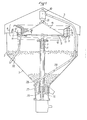
- FIG. 1 is intended to schematically illustrate a seed drill comprising a dispensing device according to the invention and more specifically a dispensing device mounted in a central hopper 1 of substantially pyramidal shape and of large capacity for simultaneously sowing up to twelve rows of seeds beets, corn or the like.
- This hopper has a body 2 for receiving the seeds and a cover 3 for filling the hopper.
- a distributor element 4 In the upper part of the hopper is positioned a distributor element 4.
- This distributor element consists of a rotary plate 5 extending by a peripheral ring 6.
- the plate 5 is mounted for rotation on a vertical axis 7 mounted in a vertical sleeve 8 opening at the lower end of the hopper.
- This axis 7 is rotated by means of a known type of transmission system such as a sprocket and chain system as well as a gearbox from one of the drive wheels so that its speed of rotation is proportional to the forward speed of the seed drill.
- the peripheral ring 6 has, in the embodiment of FIGS. 1 to 3, holes 9 with axes substantially parallel to the axis of rotation which are regularly distributed angularly according to a circle 10 of the ring 6.
- the diameter of the holes 9 and l the thickness of the crown 6 corresponds substantially to the diameter of a seed and the rotary plate 5 is removably mounted on the axis 7 in order to be able to change the rotary plate 5 and adapt it to the seeds to be sown.
- the zone of the peripheral crown 6 comprising the holes 9 is rotated above a fixed crown 11 which is mounted by means of support arms 12 on the vertical sleeve 8.
- the fixed crown 11 comprises at the right of. the path of the holes 9 of the movable ring 6, at least one orifice 13 which communicates with the input of a transport device 14.
- twelve orifices 13 are provided while being regularly angularly spaced on the crown 11, which makes it possible to supply twelve transport devices 14 and consequently be able to sow up to twelve rows.
- two internal and external fixed walls 15, 16 radially delimit the crown 11 at the orifices 13 so as to define distribution stations 17.
- the internal fixed wall 15 comprises, upstream of each distribution station 17, a window 18 formed by a cutout of the lower edge of the internal wall 15. It is possible to provide a shutter device, not shown, which makes it possible to completely or partially close the window 18, and consequently either to put out of service the corresponding distribution station which makes it possible to regulate the number of rows to sow, or to limit the flow of seeds through the window.
- a cone element 19 which causes, due to its rotation, the seeds poured over this part towards the internal fixed wall 15 so as to pass the seeds through gravity through the windows 18.
- the distribution station 17 which is delimited by the internal and external fixed walls and by two perpendicular front and rear walls 20, 21 has a dam plate 22 positioned perpendicular to the crown 6 upstream of the orifice 13.
- This plate 22 has at its lower part a means eliminating duplicates such as a brush 23 or the like. The seeds which have passed through the window 18 accumulate against the barrier wall 22 and against the brush 23.
- the seeds whose volume is limited due to the braking of the flow rate ensured by the window 18, are jostled and roll on the surface of the movable crown 6; on the other hand the speed of rotation of the plate 5 carrying the crown 11 is chosen so as to be sufficiently slow to promote the fall of a seed in each hole 9 of the crown 6 in the area upstream of the dam 22-13.
- the seeds are brought in excess above the rotary table 1 .. 5 and they fall on the periphery of the rotary table at 24 directly in the hopper.
- the seeds are fed from the hopper on the turntable 35 by a device for feeding the seeds which is pneumatic.
- a device for feeding the seeds which is pneumatic.
- a rotary disc 25 In the bottom part of the hopper 1 is mounted on the axis 7, a rotary disc 25.
- This rotary disc 25 is provided on its upper surface with a circular groove 26 having a diameter and a depth substantially equal to the diameter of a seed. The disc is rotated below the mass of the seeds filling the bottom of the hopper 1 and the seeds are consequently entrained in the groove 26.
- Above the groove 26 is placed a vertical tube element 27 in which the seeds in the groove 26 are sucked in.
- the vertical tube element 27 opens into a chamber for taking care of the seed and the seed is propelled by pressurized air through a transfer pipe 29 into a cyclone 30 positioned above the central part of the turntable 5.
- the seeds then fall by gravity onto a distributor formed by a sphere 31 positioned at the top of the cone element 19 to improve the distribution of the seeds to the various devices of distribution.
- an air intake tube 32 comprising a nozzle 33 is mounted in each station distribution at said orifice 13.
- a groove 34 of progressively increasing depth is produced on the upper face of the fixed ring 11 between a point downstream of the barrier plate 22 and the orifice 13 communicating with the transport device.
- the transport device consists of a tube element 35 into which the seed is expelled by the air sent by the nozzle 33.
- This tube element 35 ends at the neck of a Venturi 36 coaxial with said tube element, Venturi which is connected to an air inlet pipe 37 which propels the seed into a pipe 38 going to a ploughshare of the seed drill.
- an upstream wall 39 which carries a brush or the like 40 is substituted for the window 18 to limit the flow of seeds which arrive at the dam 22 'for eliminating duplicates.
- This element 39 which is disposed above the crown 6 between the walls 15 and 16 is inclined to repel the seeds in the centripetal direction and avoid an accumulation of seeds upstream of this element.
- a dam constituted by a wall 22 and a brush 23 is provided downstream of this first dam and upstream of the dispensing station 17, the active edge 41 of the brush being substantially at the level of the upper surface of the crown 6 and can in practice rub on it.
- this barrier means is arranged obliquely to drive the seeds towards the periphery of the distributor so as to drop them back into the hopper through a window 42 produced by an interruption of the external peripheral wall 16 .
- the holes 9 have a diameter slightly greater than the largest dimension of the seed g and if the rotary plate 6 has a thickness equal to this diameter, the fixed plate being flat, a seed coated ge or two naked seeds gn can be housed in practice in this hole without protruding above the turntable and they will escape in practice at the lower edge 41 of the dam 22-23 ( Figures 4 and 5).
- the superimposed seeds ge 'and gn' which have passed under the first element for braking the flow of seeds 39-40 will be hooked by the lower edge 41 of the second dam 22-23 but in the case illustrated in FIGS.
- a concentric groove 43 is produced in the upper face of the fixed plate 11.
- the section of this groove is such that a seed can only partially engage therein and the distance d ( Figure 7) between the outer edge of this groove and the most central generatrix of the hole 9 is less than the maximum dimension (largest diameter) of a seed but greater than its minimum dimension.
- the second seed gn 'des FIGS. 5c and 6d will be supported on the upper surface of the plate 11 or on the seed gn occupying the groove and will project sufficiently above the upper surface of the plate 6 to be ejected by the lower edge 41 of the barrier element . It is the same for an ovoid seed g '( Figure 6a) or for a seed gn' ( Figure 6b) superimposed on a seed gn engaged flat in the hole 9 'of the plate 6 without practically entering the groove 43. This ejection will be facilitated if the hole 9 'opens in the direction of the periphery of the turntable or if it has a folded edge forming an inclined plane 44 in said direction.
- the peripheral part 45 of the crown 6 has a frustoconical shape convex downwards and the holes 9 'are replaced by notches 46 with a cylindrical bottom opening out at the periphery of the crown , the width of these notches being, like the diameter of a hole 9, slightly greater than the largest dimension of a seed.
- the peripheral wall 47 delimiting the groove 43 has a concave frustoconical upper edge 44 to cooperate with the lower surface of the peripheral part 45.
- a single seed g, ge or gn whether it is ovoid ( Figure 9a), spheroid ( Figure 9b) or hemispheroid ( Figures 9c to 9f) can engage in a notch 46 and possibly the groove 43 without protruding above the upper surface. Consequently, the seeds likely to form doubles will be ejected the seeds g 1 and gn 1 (FIGS. 9a and 9d) by the braking element 39, 40 and the seeds g ', ge' and gn 'by the edge 41 dam 22, 23.
- the dispensing station at the right of which the seeds are brought to the orifice 13 of the inlet of the transport device consists of a solid part 48 which delimits by its internal surface the tray of the rotary crown and in which a bore 13 'is made in coincidence with the orifice 13 to constitute the suction orifice of the Venturi of the transport device.
- the part 48 Upstream, the part 48 has a cut plane 49 which returns inward the seeds which have not found passage through the neck or tunnel which will be discussed below and a left surface in ploughshare 50 directed outwards and which drives out notches 46 the seeds forming doubles as will be explained below.
- a radial partition 51 which goes from the peripheral wall 16 to the edge of the cutaway 49 of the piece 48.
- the lower corner next to the cutaway 49 of this partition 51 is cut, to the right notches 46 and groove 43, at 52 to allow the free passage of seeds.
- the edge of the fixed plate 11 is notched at 53 as clearly visible in the drawing to form an inclined plane 54 ending at the top of the external wall 43 of the socket of the rotary plate 6 in the fixed plate 11.
- the seeds which have passed through the tunnel 52 while being supported on the concave frustoconical surface 44 without being engaged in the space delimited by the notch 46 and the wall 43 below the upper edge of the latter will no longer be supported and fall, along the inclined plane 54, into the hopper which is located below the dispenser. If a seed that is not engaged in the space above is trapped by the seed engaged behind the wall 43 against the wall of the notch 46 while projecting above the upper edge of the crown 6, it comes into contact of the surface 50 which causes it to tilt outwards on the inclined plane 54. The position of these seeds being unstable, they are not likely to be sheared by the lower edge of the. surface 50.
Priority Applications (1)
| Application Number | Priority Date | Filing Date | Title |
|---|---|---|---|
| AT81400498T ATE13795T1 (de) | 1980-03-31 | 1981-03-27 | Verteilervorrichtung fuer praezisionssaemaschine. |
Applications Claiming Priority (6)
| Application Number | Priority Date | Filing Date | Title |
|---|---|---|---|
| FR8007190 | 1980-03-31 | ||
| FR8007190A FR2478941A1 (fr) | 1980-03-31 | 1980-03-31 | Dispositif distributeur pour semoir dit " monograine " et semoir comportant un tel dispositif |
| FR8017894A FR2488480A1 (fr) | 1980-08-13 | 1980-08-13 | Dispositif distributeur pour semoir dit " monograine " et semoir comportant un tel dispositif |
| FR8017894 | 1980-08-13 | ||
| FR8103317A FR2499816B2 (fr) | 1981-02-19 | 1981-02-19 | Dispositif distributeur pour semoir dit " monograine " et semoir comportant un tel dispositif |
| FR8103317 | 1981-02-19 |
Publications (3)
| Publication Number | Publication Date |
|---|---|
| EP0037337A2 true EP0037337A2 (de) | 1981-10-07 |
| EP0037337A3 EP0037337A3 (en) | 1982-11-17 |
| EP0037337B1 EP0037337B1 (de) | 1985-06-19 |
Family
ID=27250996
Family Applications (1)
| Application Number | Title | Priority Date | Filing Date |
|---|---|---|---|
| EP81400498A Expired EP0037337B1 (de) | 1980-03-31 | 1981-03-27 | Verteilervorrichtung für Präzisionssämaschine |
Country Status (4)
| Country | Link |
|---|---|
| US (1) | US4403713A (de) |
| EP (1) | EP0037337B1 (de) |
| AU (1) | AU541820B2 (de) |
| DE (1) | DE3170996D1 (de) |
Cited By (8)
| Publication number | Priority date | Publication date | Assignee | Title |
|---|---|---|---|---|
| FR2524762A1 (fr) * | 1982-04-09 | 1983-10-14 | Sogefina | Dispositif selecteur pour distributeur de semoir dit " monograine " |
| FR2574243A1 (fr) * | 1984-12-11 | 1986-06-13 | Gras Jean | Machine a semer des graines par exemple des graines d'ail |
| FR2583256A1 (fr) * | 1985-06-18 | 1986-12-19 | Limagrain | Appareil d'epandage de capsules d'oeufs d'insectes en lutte biologique |
| EP0338647A1 (de) * | 1988-04-21 | 1989-10-25 | C. van der Lely N.V. | Düngerstreuer |
| FR2649282A1 (fr) * | 1989-07-06 | 1991-01-11 | Morisseau Jean Paul | Appareil pour la distribution d'elements en forme de graines ou similaires, et semoir equipe d'un tel appareil |
| WO1994026090A2 (en) * | 1993-05-19 | 1994-11-24 | British Technology Group Limited | Dibber drills |
| FR2713437A1 (fr) * | 1993-12-10 | 1995-06-16 | Gerplant Automation | Semoir perfectionné. |
| WO2016135174A1 (de) * | 2015-02-26 | 2016-09-01 | Gerald Funck | Vereinzelungsaggregat für körniges gut |
Families Citing this family (7)
| Publication number | Priority date | Publication date | Assignee | Title |
|---|---|---|---|---|
| CA2194016C (en) * | 1994-07-04 | 2005-05-31 | Donald Harry Sandbrook | Vertical axis metering device for a particulate material dispenser |
| US6109193A (en) | 1995-12-29 | 2000-08-29 | Case Corporation | Seed planter apparatus and method |
| US6564730B2 (en) | 1995-12-29 | 2003-05-20 | Case Corporation | Seed planter apparatus and method |
| US6044779A (en) * | 1998-04-15 | 2000-04-04 | Case Corporation | Multiple drop seed disc |
| SE520798C2 (sv) * | 2001-02-22 | 2003-08-26 | Vaederstad Verken Ab | Granulatfördelaranordning |
| SE524649C2 (sv) * | 2002-07-05 | 2004-09-14 | Vaederstad Verken Ab | Anordning för åtskild fördelning av granuler |
| GB0217297D0 (en) * | 2002-07-26 | 2002-09-04 | Cnh Belgium Nv | Methods of optimising stochastic processing parameters in crop harvesting machines |
Family Cites Families (4)
| Publication number | Priority date | Publication date | Assignee | Title |
|---|---|---|---|---|
| US658450A (en) * | 1900-04-26 | 1900-09-25 | Henry C Kettler | Seed-planter. |
| US2665005A (en) * | 1948-12-02 | 1954-01-05 | C T Small Mfg Company | Feeding device for caps and the like |
| US2777561A (en) * | 1952-07-09 | 1957-01-15 | Rose Brothers Ltd | Feeding of articles in wrapping or packaging machines |
| US3322080A (en) * | 1965-05-19 | 1967-05-30 | Harold E Gatzke | Method and apparatus for hydraulic seed metering and planting |
-
1981
- 1981-03-27 DE DE8181400498T patent/DE3170996D1/de not_active Expired
- 1981-03-27 EP EP81400498A patent/EP0037337B1/de not_active Expired
- 1981-03-31 AU AU68923/81A patent/AU541820B2/en not_active Ceased
- 1981-03-31 US US06/249,367 patent/US4403713A/en not_active Expired - Lifetime
Non-Patent Citations (2)
| Title |
|---|
| "Eléments de la technique relevés: Néant" * |
| Néant * |
Cited By (11)
| Publication number | Priority date | Publication date | Assignee | Title |
|---|---|---|---|---|
| FR2524762A1 (fr) * | 1982-04-09 | 1983-10-14 | Sogefina | Dispositif selecteur pour distributeur de semoir dit " monograine " |
| EP0091863A1 (de) * | 1982-04-09 | 1983-10-19 | Société SOGEFINA Société de Gestion Financière Armoricaine (Société Anonyme) | Auslesevorrichtung für den Verteiler einer Einzelkornsämaschine |
| US4646939A (en) * | 1982-04-09 | 1987-03-03 | Societe Sogefina, Societe De Gestion Financiere Armoricaine (Societe Anonyme) | Selector device for the distributor of a so-called "single seed" seed drill |
| FR2574243A1 (fr) * | 1984-12-11 | 1986-06-13 | Gras Jean | Machine a semer des graines par exemple des graines d'ail |
| FR2583256A1 (fr) * | 1985-06-18 | 1986-12-19 | Limagrain | Appareil d'epandage de capsules d'oeufs d'insectes en lutte biologique |
| EP0338647A1 (de) * | 1988-04-21 | 1989-10-25 | C. van der Lely N.V. | Düngerstreuer |
| FR2649282A1 (fr) * | 1989-07-06 | 1991-01-11 | Morisseau Jean Paul | Appareil pour la distribution d'elements en forme de graines ou similaires, et semoir equipe d'un tel appareil |
| WO1994026090A2 (en) * | 1993-05-19 | 1994-11-24 | British Technology Group Limited | Dibber drills |
| WO1994026090A3 (en) * | 1993-05-19 | 1995-01-05 | British Tech Group | Dibber drills |
| FR2713437A1 (fr) * | 1993-12-10 | 1995-06-16 | Gerplant Automation | Semoir perfectionné. |
| WO2016135174A1 (de) * | 2015-02-26 | 2016-09-01 | Gerald Funck | Vereinzelungsaggregat für körniges gut |
Also Published As
| Publication number | Publication date |
|---|---|
| AU6892381A (en) | 1982-01-21 |
| DE3170996D1 (en) | 1985-07-25 |
| EP0037337B1 (de) | 1985-06-19 |
| EP0037337A3 (en) | 1982-11-17 |
| AU541820B2 (en) | 1985-01-24 |
| US4403713A (en) | 1983-09-13 |
Similar Documents
| Publication | Publication Date | Title |
|---|---|---|
| EP0037337B1 (de) | Verteilervorrichtung für Präzisionssämaschine | |
| EP2854499B1 (de) | Einzelkornsämaschine und kornvereinzelungsscheibe mit offenen rillen | |
| EP0536768B1 (de) | Verteiler für eine Einzelkörnersämaschine | |
| EP0598636B1 (de) | Einzelkornsämaschine | |
| EP2953443B1 (de) | Einzelkornsämaschine mit wenigstens einer verbesserten säelement | |
| EP3238519B1 (de) | Reguliervorrichtung der verteilung von samen für sämaschine, und entsprechende sämaschine | |
| FR2464017A1 (fr) | Semeuse de precision | |
| EP3238518B1 (de) | Sämaschine, die mit einer vorrichtung zur regulierung der samenverteilung ausgestattet ist, und entsprechende reguliervorrichtung | |
| EP2672804B1 (de) | Verteilerkasten für einzelsämaschine mit rührklingen und sämaschine mit einem solchen kasten | |
| EP0091863B1 (de) | Auslesevorrichtung für den Verteiler einer Einzelkornsämaschine | |
| EP0636306B1 (de) | Verteilungskasten für eine mechanische Einzelkörnersämaschine | |
| FR2574243A1 (fr) | Machine a semer des graines par exemple des graines d'ail | |
| FR2478941A1 (fr) | Dispositif distributeur pour semoir dit " monograine " et semoir comportant un tel dispositif | |
| EP1488674B1 (de) | Pneumatischer Saatgutverteiler | |
| FR2488480A1 (fr) | Dispositif distributeur pour semoir dit " monograine " et semoir comportant un tel dispositif | |
| EP0060753B1 (de) | Dosiergeräte zum Abfüllen von Füllgut in Behälter | |
| FR2643212A1 (fr) | Dispositif de reglage d'un distributeur pour semoir monograine | |
| EP3476192B1 (de) | Dosiervorrichtung der verteilung von saatkörnern für eine sämaschine, und entsprechende sämaschine | |
| FR3134947A1 (fr) | Dispositif d’accélération d’au moins un élément granulaire de préférence une graine | |
| BE524576A (de) | ||
| BE694678A (de) | ||
| FR2607778A1 (fr) | Distributeur tangentiel de bouchons ou analogues | |
| BE554060A (de) | ||
| FR2496389A3 (fr) | Semoir | |
| FR2500993A1 (fr) | Dispositif de ramassage et de chargement de plantes, telles que des betteraves, des pommes de terre,... |
Legal Events
| Date | Code | Title | Description |
|---|---|---|---|
| PUAI | Public reference made under article 153(3) epc to a published international application that has entered the european phase |
Free format text: ORIGINAL CODE: 0009012 |
|
| AK | Designated contracting states |
Designated state(s): AT BE CH DE GB IT LU NL SE |
|
| PUAL | Search report despatched |
Free format text: ORIGINAL CODE: 0009013 |
|
| AK | Designated contracting states |
Designated state(s): AT BE CH DE GB IT LU NL SE |
|
| 17P | Request for examination filed |
Effective date: 19830328 |
|
| GRAA | (expected) grant |
Free format text: ORIGINAL CODE: 0009210 |
|
| AK | Designated contracting states |
Designated state(s): AT BE CH DE GB IT LI LU NL SE |
|
| PG25 | Lapsed in a contracting state [announced via postgrant information from national office to epo] |
Ref country code: SE Effective date: 19850619 Ref country code: NL Effective date: 19850619 Ref country code: IT Free format text: LAPSE BECAUSE OF FAILURE TO SUBMIT A TRANSLATION OF THE DESCRIPTION OR TO PAY THE FEE WITHIN THE PRESCRIBED TIME-LIMIT;WARNING: LAPSES OF ITALIAN PATENTS WITH EFFECTIVE DATE BEFORE 2007 MAY HAVE OCCURRED AT ANY TIME BEFORE 2007. THE CORRECT EFFECTIVE DATE MAY BE DIFFERENT FROM THE ONE RECORDED. Effective date: 19850619 Ref country code: AT Effective date: 19850619 |
|
| REF | Corresponds to: |
Ref document number: 13795 Country of ref document: AT Date of ref document: 19850715 Kind code of ref document: T |
|
| REF | Corresponds to: |
Ref document number: 3170996 Country of ref document: DE Date of ref document: 19850725 |
|
| NLV1 | Nl: lapsed or annulled due to failure to fulfill the requirements of art. 29p and 29m of the patents act | ||
| PG25 | Lapsed in a contracting state [announced via postgrant information from national office to epo] |
Ref country code: LU Free format text: LAPSE BECAUSE OF NON-PAYMENT OF DUE FEES Effective date: 19860331 Ref country code: LI Effective date: 19860331 Ref country code: CH Effective date: 19860331 |
|
| PLBE | No opposition filed within time limit |
Free format text: ORIGINAL CODE: 0009261 |
|
| STAA | Information on the status of an ep patent application or granted ep patent |
Free format text: STATUS: NO OPPOSITION FILED WITHIN TIME LIMIT |
|
| 26N | No opposition filed | ||
| REG | Reference to a national code |
Ref country code: CH Ref legal event code: PL |
|
| PGFP | Annual fee paid to national office [announced via postgrant information from national office to epo] |
Ref country code: GB Payment date: 20000322 Year of fee payment: 20 |
|
| PGFP | Annual fee paid to national office [announced via postgrant information from national office to epo] |
Ref country code: BE Payment date: 20000403 Year of fee payment: 20 |
|
| PGFP | Annual fee paid to national office [announced via postgrant information from national office to epo] |
Ref country code: DE Payment date: 20000415 Year of fee payment: 20 |
|
| BE20 | Be: patent expired |
Free format text: 20010327 *SOC. SOGEFINA SOC. DE GESTION FINANCIERE ARMORICAINE |
|
| PG25 | Lapsed in a contracting state [announced via postgrant information from national office to epo] |
Ref country code: GB Free format text: LAPSE BECAUSE OF EXPIRATION OF PROTECTION Effective date: 20010326 |
|
| REG | Reference to a national code |
Ref country code: GB Ref legal event code: PE20 Effective date: 20010326 |