EP3476192B1 - Dosiervorrichtung der verteilung von saatkörnern für eine sämaschine, und entsprechende sämaschine - Google Patents
Dosiervorrichtung der verteilung von saatkörnern für eine sämaschine, und entsprechende sämaschine Download PDFInfo
- Publication number
- EP3476192B1 EP3476192B1 EP18197691.1A EP18197691A EP3476192B1 EP 3476192 B1 EP3476192 B1 EP 3476192B1 EP 18197691 A EP18197691 A EP 18197691A EP 3476192 B1 EP3476192 B1 EP 3476192B1
- Authority
- EP
- European Patent Office
- Prior art keywords
- seed
- seeds
- tooth
- wheel
- regulating device
- Prior art date
- Legal status (The legal status is an assumption and is not a legal conclusion. Google has not performed a legal analysis and makes no representation as to the accuracy of the status listed.)
- Active
Links
- 238000009331 sowing Methods 0.000 claims description 46
- 230000001105 regulatory effect Effects 0.000 claims description 39
- 238000011144 upstream manufacturing Methods 0.000 claims description 8
- 238000010899 nucleation Methods 0.000 claims description 3
- 230000007704 transition Effects 0.000 claims description 2
- 230000001276 controlling effect Effects 0.000 claims 1
- 230000032258 transport Effects 0.000 description 16
- 244000007853 Sarothamnus scoparius Species 0.000 description 13
- 240000008042 Zea mays Species 0.000 description 9
- 235000002017 Zea mays subsp mays Nutrition 0.000 description 9
- 238000013459 approach Methods 0.000 description 9
- 210000003323 beak Anatomy 0.000 description 9
- 235000005824 Zea mays ssp. parviglumis Nutrition 0.000 description 8
- 235000005822 corn Nutrition 0.000 description 8
- 230000005484 gravity Effects 0.000 description 8
- 240000002791 Brassica napus Species 0.000 description 6
- 235000004977 Brassica sinapistrum Nutrition 0.000 description 5
- 241000209140 Triticum Species 0.000 description 5
- 235000021307 Triticum Nutrition 0.000 description 5
- 230000000717 retained effect Effects 0.000 description 5
- 230000008901 benefit Effects 0.000 description 4
- 230000000694 effects Effects 0.000 description 4
- 238000012423 maintenance Methods 0.000 description 4
- 239000000047 product Substances 0.000 description 4
- 230000003111 delayed effect Effects 0.000 description 3
- 239000000463 material Substances 0.000 description 3
- 241000201976 Polycarpon Species 0.000 description 2
- 230000009471 action Effects 0.000 description 2
- 235000013339 cereals Nutrition 0.000 description 2
- 230000001934 delay Effects 0.000 description 2
- 230000002452 interceptive effect Effects 0.000 description 2
- 230000001788 irregular Effects 0.000 description 2
- 230000007246 mechanism Effects 0.000 description 2
- 239000002245 particle Substances 0.000 description 2
- 230000001739 rebound effect Effects 0.000 description 2
- 239000002689 soil Substances 0.000 description 2
- 244000075850 Avena orientalis Species 0.000 description 1
- 235000007319 Avena orientalis Nutrition 0.000 description 1
- 235000021537 Beetroot Nutrition 0.000 description 1
- 235000016068 Berberis vulgaris Nutrition 0.000 description 1
- 241000335053 Beta vulgaris Species 0.000 description 1
- 235000011293 Brassica napus Nutrition 0.000 description 1
- 241000196324 Embryophyta Species 0.000 description 1
- 241000209082 Lolium Species 0.000 description 1
- 235000010582 Pisum sativum Nutrition 0.000 description 1
- 240000004713 Pisum sativum Species 0.000 description 1
- 229920000297 Rayon Polymers 0.000 description 1
- 235000016383 Zea mays subsp huehuetenangensis Nutrition 0.000 description 1
- 230000000903 blocking effect Effects 0.000 description 1
- 238000009933 burial Methods 0.000 description 1
- 230000005465 channeling Effects 0.000 description 1
- 230000000295 complement effect Effects 0.000 description 1
- 238000013016 damping Methods 0.000 description 1
- 230000006837 decompression Effects 0.000 description 1
- 239000000428 dust Substances 0.000 description 1
- 229920001971 elastomer Polymers 0.000 description 1
- 230000005611 electricity Effects 0.000 description 1
- 239000003337 fertilizer Substances 0.000 description 1
- 230000006872 improvement Effects 0.000 description 1
- 235000021374 legumes Nutrition 0.000 description 1
- 235000009973 maize Nutrition 0.000 description 1
- 239000004033 plastic Substances 0.000 description 1
- 229920003023 plastic Polymers 0.000 description 1
- 229920002635 polyurethane Polymers 0.000 description 1
- 239000004814 polyurethane Substances 0.000 description 1
- 239000002964 rayon Substances 0.000 description 1
- 239000010902 straw Substances 0.000 description 1
- 239000013589 supplement Substances 0.000 description 1
Images


Classifications
-
- A—HUMAN NECESSITIES
- A01—AGRICULTURE; FORESTRY; ANIMAL HUSBANDRY; HUNTING; TRAPPING; FISHING
- A01C—PLANTING; SOWING; FERTILISING
- A01C7/00—Sowing
- A01C7/04—Single-grain seeders with or without suction devices
-
- A—HUMAN NECESSITIES
- A01—AGRICULTURE; FORESTRY; ANIMAL HUSBANDRY; HUNTING; TRAPPING; FISHING
- A01C—PLANTING; SOWING; FERTILISING
- A01C7/00—Sowing
- A01C7/08—Broadcast seeders; Seeders depositing seeds in rows
- A01C7/12—Seeders with feeding wheels
- A01C7/14—Seeders with spoon or bucket wheels
Definitions
- the field of the invention is that of row seeders, in particular for sowing cereals or legumes.
- the invention relates more precisely to the improvement of the distribution on the ground of the seeds at the time of their distribution, and relates in particular to the regulation of the distribution, downstream of a distribution and metering device of a sowing element.
- seeds is understood here to mean seeds, and more generally any particles capable of being distributed in the same way, for example particles of fertilizer or seedling protection (anti-slug, for example).
- precision seed drills have been developed, often called precision seed drills. These precision seed drills are designed to specifically sow a predetermined type of seed (corn, beet, etc.). They are used for inter-row crops greater than 25 cm. Each row is generally supplied with seeds by an individual hopper connected to its own distribution, burial and reconsolidation members. These seeders are efficient, but at the cost of relatively high complexity. They have specific means, suitable for seizing seeds They are bulky, require many adjustments, an energy supply (in particular pneumatic, to provide a vacuum allowing to maintain the seeds one by one) adapted, and require seeds used to be precisely calibrated. The Precision seed drills are consequently expensive, and reserved for certain specific situations.
- single-grain seeders lack versatility, and in particular have a size such that they do not allow the sowing of certain seeds, for example wheat, for which an inter-row spacing of less than 25 cm is desired.
- multigrain seeders used in particular for cereals, such as wheat or oats. They also make it possible to carry out direct sowing, the seeds being distributed to each sowing unit by means of a metering and transport device, fed by a hopper containing the seeds and directing the seeds towards the ground via a transfer duct. .
- a metering device is generally placed under the hopper, and is equipped with one or more wheels provided with cells or teeth forming lugs, capable of receiving a determined volume of seeds (the wheels being adapted to the type of seed to be sow).
- the applicant has proposed, in order to distribute the seeds more homogeneously, to regulate the distribution of the seeds by adding a buffer tank arranged on the path of the seeds, between the metering and transport device. and the end of the duct, close to the ground.
- This approach is described in particular in the patent document FR2691040 , which thus presents a regulation system implementing a plurality of diabolos arranged at the outlet of the metering device.
- the diabolos seize the seeds as soon as they come out of the metering unit through a supply chute which serves as a buffer reserve, for cushion the effect of packet arrivals and seed gaps.
- the V-shape of the diabolo makes it possible to collect and trap the seeds to align them one after the other, with better precision.
- the regulator is sensitive to jolts. It must be placed immediately following the metering unit, and therefore remains away from the ground. As a result, a large part of the gain in seed distribution regularity is here also canceled out during the transport of the seed between the outlet of the regulator and the soil. Additionally, seed blockages may appear in a dolly, reintroducing shortages, followed by bundles upon release.
- the applicant has proposed to regulate the distribution of the seeds by associating with a buffer tank placed on the seed path, a wheel capable of collecting seeds. in a reserve zone, by means of at least one row of teeth, each ensuring the removal of a seed in the reserve zone, each tooth having a housing suitable for receiving a seed (approach described for example in the documents of patent EP3238518 and EP3238519 , not published at the priority date of the present application).
- the invention responds to this need by proposing a regulation device for a seed drill, intended to supply seeds with a sowing element of a seed drill and intended to be mounted downstream of the seed metering and transport means, said control device comprising a reserve zone, supplied with seeds via a supply input connected to said metering and transport means.
- the regulating device comprises an inlet connected to said metering and transport means and an outlet connected to said sowing element.
- a guide portion also called a slide
- a guide groove ensures precise maintenance and guidance of each seed, which moves progressively in the groove, to be released at the desired time, so as to ensure simple and efficient regulation of seed distribution.
- the edges of the groove prevent the seed from falling accidentally on one side of the wheel, and ensure that this seed is effectively directed towards the beak of the tooth, before being released.
- the bottom of the groove is below the level of the housing exit zone, i.e. the distance between the center of the wheel and the bottom of the groove is less than the distance between this center and the exit area.
- This slide of relatively long length L, according to the invention has many advantages.
- the seed is not held strongly in the housing (at the risk of a possible blockage), but can quickly reach the slide, which forms a "relaxation” or “decompression” zone, gradually guiding the seed, for better control the moment of his release.
- the groove has a shape, in particular a section (for example in V or U), adapted to prevent any fall of the seed during its transport, for example by tilting of the seed on one side or the other of the back of the tooth.
- the seed is thus guided and centered within the tooth, its path being precisely defined along the slide.
- the tooth may have, in the extension of the slide, a point forming a beak, the upper part of said beak being curved towards said wheel (for example by substantially defining a portion of ellipse), and the lower part of said corresponding beak. to an upper portion of said housing.
- This spout corresponds to the exit zone of the slide and its throat, or of release of the seed, and can in this sense be likened to a pouring spout.
- said housing substantially defines, in the plane of the wheel, a semicircle with a radius Ri of between 1 and 10 mm, and said length L is at least three times said radius Ri.
- the radius Ri of the housing is chosen so that the housing can receive a single seed, i.e. it is slightly greater than the radius of a reference sphere representing the type of seed (corn, wheat, rapeseed , ...) for which the wheel is intended.
- a single seed can be placed in a housing. It is indeed important that only one seed is present in each housing, to ensure the desired regular distribution.
- the tines are not intended to contain several seeds: the regulation device is not intended for sowing in pockets, but seed by seed.
- the spout has an upper surface defining a portion of ellipse makes it possible in particular to grasp each seed in the reserve zone without damaging it.
- the substantially semi-circular shape of the housing makes it possible to maintain the single seed taken in the reserve zone, within the tooth even in the event of jolts or vibrations, without risking to block it (which could happen for example if the shape of the housing differed from the shape of the seed, and created areas of friction between the housing and the seed).
- the shape of the housing is thus adapted to the shape of the seeds to be sown. Its dimensions vary according to the type of seeds to be sown (a given wheel is therefore adapted to a type of seed).
- said groove may comprise a first transition portion, adjacent to the housing of the following tooth, forming a ramp directed towards a second portion of the groove, called a gutter, ensuring the guidance of the seed towards the tip of the tooth.
- the seed leaving the housing is thus gradually guided towards the back of the throat, smoothly and risk of rebound.
- the surface of the ramp may in particular substantially form a triangle.
- said gutter can extend in a substantially rectilinear fashion.
- the slide defines a substantially rectilinear path.
- the depth of said groove represents substantially half of the radius Ri.
- said groove may comprise a third portion, called a release portion, at the level of the beak of the tooth, in which the upper edges of the second portion approach one another.
- said wheel comprises at least two rows of teeth separated by a central space.
- the presence of at least two rows of teeth makes it possible to produce a compact regulating device, since it makes it possible to transport at least twice as many seeds as a device comprising a single row.
- the presence of at least two rows of teeth can act as a seed agitator in the reserve zone: in fact, when a row of teeth takes a seed from the reserve zone, the other seeds of the area may be naturally pushed towards the other row (s) of teeth.
- the teeth of a first row can in particular be arranged staggered with respect to the teeth of a second row.
- the wheel comprises several rows of teeth
- the latter are advantageously angularly offset with respect to each other, in order to regularly and alternately release the seeds of each of the rows.
- said at least one row of teeth can be arranged at a distance from a wall of said device less than or equal to 1 mm.
- each row of teeth is placed as close as possible to the wall of the housing, so as not to allow any passage of seeds along this wall.
- each of said teeth has at least one side wall, at least on a portion of said housing.
- Such a wall can make it possible to keep the seed inside the housing, without it being able to escape laterally, then, if necessary, to guide it towards the slide.
- said wheel can be driven in rotation by a motor located at least partly inside said wheel.
- the regulating device forms a consolidated module capable of being fixed on mobile elements such as sowing elements of the seeder.
- a motor can in particular be electric, and the speed of the motor can be controlled by the dose which distribution and dosage means arrive, in order to have a complete filling of the teeth. This speed can be proportional to the forward speed of the seed drill.
- said wheel is selected from among a plurality of wheels each adapted to a type, a size and / or a dose of seeds to be transported.
- the wheels used can be interchanged when the variety and / or the dose of seeds to be sown varies.
- Said mobile retaining means may for example comprise at least one brush comprising an assembly of bristles of which at least the free part extends substantially tangentially to the wheel and substantially vertically.
- the bristles of the broom hold the seed against the back of the tine, until they pass into the release position, in which they are moved away from the wheel.
- said supply inlet to said reserve comprises an inclined plane, directing the seeds towards a step formed substantially at mid-height of said regulating device, so as to slow down the seeds arriving in said reserve zone.
- the invention also relates to a seed drill implementing at least one control device as described above.
- FIG. 1A An example of a disc seed drill implementing the invention is illustrated on figure 1A .
- a planter structure of this type is in particular described in the patent document EP1212932 or EP2060163 .
- sowing elements 12 This seeder is supported on the ground by means of the sowing elements 12.
- sowing elements 12 In the side view of the figure 1A , only one sowing unit is shown. In reality, several similar sowing elements are implemented in parallel.
- the seeder is equipped with a hopper 13, fixed on a frame 11 and intended to contain the seeds of seeds.
- the seeds are distributed mechanically.
- Metering devices 17a, 17b remove the seeds from the bottom of the hopper 13, for example using a rotating metering wheel.
- the distribution can also be pneumatic.
- a compressed air generator supplies a stream of compressed air to a distribution and distribution head, and the seeds picked up by the metering device are inserted into the air stream.
- the invention can also be implemented on a coulter seeder, as described for example in the patent document FR2658380 .
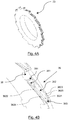
- the figure 1B illustrates a coulter of such a seed drill, conventional in itself, comprising a body 2 at the base of which is mounted a profiled and arched wearing part 3. The front part of the share points to the left in this figure.
- the share is equipped with a regulating device 4 (described in more detail below), receiving seeds from the hopper, in the same way as explained above, via the duct 5.
- the device for regulation 4 delivers the seeds regularly in the body of the share 2, which directs them towards the wearing part 3 which forms a groove.
- the invention proposes an effective and simple solution to implement to allow a more homogeneous distribution of seeds, in particular for seeds requiring to be deposited one by one in a furrow on the ground, in a aligned manner and at regular intervals, such as seeds of wheat, rapeseed, corn, beetroot, peas, etc.
- the general principle of the invention is thus based on the implementation of a mechanically driven regulation device (without pneumatic means, at the level of this regulation device, as opposed to precision seed drills), in addition to a control device.
- metering and transport hereinafter called metering device
- metering device conventionally used in a seed drill.
- a seeder according to the invention comprises both a conventional metering device, placed at the outlet of the hopper, and a regulating device according to the invention, placed at the output of the metering device, near the ground.
- This regulation device is placed on the path of the seeds between the metering device and the means for planting the seeds, or sowing means.
- the regulation device is placed "in cut”, or “in series”, by analogy to the vocabulary of electricity, on the transfer conduit (151a, 151b or 5) which usually directly connects the metering device to the means. of planting.
- This transfer duct is therefore broken down into two parts, an upstream part connecting the outlet of the metering device to the inlet of the regulation device, and a downstream part connecting the outlet of the regulation device to the earthing means.
- this “cutting” of the transfer duct can be performed not only on a new sowing unit, but also on an existing sowing unit, to improve the precision thereof. It suffices to mount a regulating device according to the invention on the existing transfer duct.
- the regulation device therefore receives the seeds delivered by the metering device. Despite the efforts made for the effectiveness of such devices, it happens that the seeds are delivered "in packets", and that there are times without seed delivered.
- the control device receives these seeds, keeps a “buffer” reserve, and delivers them to the planting means as regularly as possible, one by one and at regular intervals, as much as possible.
- the regulation device is brought closer to the ground, relative to the position of the metering device which is located at the level of the base of the hopper (and preferably placed as close as possible to the ground). It can in particular be fixed to the sowing element, at the inlet of the cannula or of the share which directs the seeds towards the ground: the gain in regularity offered by the system is thus preserved when the seeds are deposited on the ground. The seeds are thus sown one after the other, in a regular and unitary manner or practically unitary.
- the treatment of the seeds is therefore gravity, for the setting and for the release of the seeds. It is purely mechanical, and does not require the presence of pneumatic means.
- the control device should not be confused with a dosing device, which it supplements, but does not replace.
- the two devices do not have the same functions.
- the metering device is placed directly under the hopper, and therefore receives the seeds directly from the latter, which assumes a strong pressure, due to the mass of seeds present in the hopper.
- the regulation device is on the other hand an element of reduced size, for example having a lateral face of the order of 10 cm x 10 cm, and a width of 3 to 5 cm. It has a buffer seed reserve, which contains only a few tens or hundreds of seeds (depending on the size of these), which are therefore not subjected to strong pressure.
- the output precision (i.e. adherence to one-to-one seed distribution with a desired time, or space, interval at ground level) of the metering device is generally of the order of 40%, that of a regulation device according to the invention can reach of the order of 75% to 80%, or even more under certain conditions.
- the device of the invention makes it possible to obtain a precision close to that of a precision seeder, without the complexity of the latter, and while offering versatility on the different types of seeds.
- Such a regulating device comprises a wheel provided with at least one row of teeth forming buckets (each capable of carrying a single seed inside the housing formed by this bucket), driven in rotation.
- This wheel housed in a housing, draws the seeds from a seed reserve supplied by the metering device, via an upstream part of a transfer duct, and transports them, in its buckets, to a downstream part of a transfer duct (for example the aforementioned cannula).
- each tooth has a tooth back of considerable length, having a groove forming means for maintaining and guiding the seed in which the seed moves progressively to control, in particular to delay, the release of the seed. .
- the back of the tooth forms a slide for the seed, and the groove with which it is provided makes it possible to guide, or channel, the seed along the tooth and to prevent it from falling, during its movement, by for example by tilting by one or the other of the sides of the tine, which would risk causing position shifts and / or delays in the deposit of seeds on the ground.
- Such a phenomenon of seed drop may for example take place when the surface of the back of the tine is full, and is accentuated when the seeds are round, as is the case in particular with rapeseed or corn.
- This groove also allows the role of temporally separating possible duplicates of seeds, which would have been taken and kept in the housing.
- the seeds of a duplicate will be delivered close to each other (too close, relative to the rate of the desired regulation), but still one after the other.
- This tooth profile if necessary combined with additional retaining means, for example a broom, allows the seed to be released (at the earliest) only after it has passed a horizontal straight line passing through the axis of the wheel. In this way, the seed is subjected, in its fall, only to the effect of gravity, and falls substantially vertically as far as possible. It is not subjected to deviations or to centrifugal force, coming out of the tooth early, which could cause rebounds on the edges of the cannula, and therefore also position shifts and / or delays.
- figure 2 represents the current seed distribution system.
- This small-footprint regulating device can easily be fitted to a traditional sowing unit fitted with a conventional metering device, so as to improve the precision and efficiency of the sowing operation.
- the regulation device is formed by a housing 22 comprising two communicating compartments 22a, 22b.
- the first compartment 22a forms a reserve of seeds, called a “buffer reserve”, where seeds 100 from the metering device (not shown) accumulate, while the second compartment 22b houses a wheel 23 with buckets, from which collect the seeds 100. one by one in the buffer reserve.
- the seeds 100 arrive, in this first embodiment, from the metering unit to the first compartment 22a of the housing 22 via a downstream part of the transfer duct 24a, secured to the top of the housing 22, and connected to an upstream part of the duct. transfer 24b (or connected directly to an upper part of the cannula or the share).
- the downstream part 24a is here oriented (in the vicinity of the housing) in a direction opposite to the direction of rotation of the wheel 23, for example according to an angle ⁇ between 15 ° and 35 ° from the vertical. This makes it possible to slow down and guide the seeds, in cooperation with a wall 25, extending the downstream part firstly with the angle a, then vertically. This wall 25 isolates the seed arrival zone from the wheel 23, the compartment 22a therefore comprising a seed arrival zone and a seed gripping zone.
- the seeds are thus directed towards the gripping zone without interfering with the filling of the buckets of the wheel 23. It is indeed desirable to avoid, or at the very least to limit, the rebounds of seeds arriving in the buffer reserve, and in particular that seeds are lodged in duplicate in a tooth, or come to strike and eject a seed present in a tooth.
- An opening 29 may be provided, in the upper part of the housing, to allow the air to escape, in particular in the event of a pneumatic supply. Additional means (not shown) forming a “sock” can make it possible to direct the air, possibly charged with dust, towards the ground.
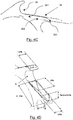
- the upstream part 51 of the conduit bringing the seeds delivered by the metering device is substantially vertical.
- the seeds arrive on an inclined plane 52, for example forming an angle of the order of 35 to 50 ° with the vertical axis defined by the upstream part 51 of the duct.
- This inclined plane 52 directs the seeds towards a step 53, substantially horizontal, which is extended downwards by a second inclined plane 54, also forming an angle ⁇ of the order of 35 ° to 50 ° with the vertical (the two planes inclined 52 and 54 forming between them an angle of between 80 and 100 °).
- the step 53 and the second inclined plane 54 can be formed in the same part, and be extended by a bottom part 55, extending if necessary under the wheel 23, and substantially defining the buffer reserve, including the filling level optimal corresponds substantially to the position of step 53.
- the inclined plane 52 then the step 53, absorb a significant part of the energy accumulated by the seed during its fall. There are thus few rebound effects, and the seizure of the seeds by the wheel 23 is not, or only slightly, disturbed.
- This step (and possibly other elements) can be made of, or can carry, a damping material.
- an end portion 56 of the upstream part 51 of the duct has a grid provided with openings making it possible to expel the air, in particular if the seeds are transferred pneumatically.
- the pressurized air is ejected before the regulating device, and does not disturb the operation of the latter, nor the circulation of seeds in the downstream part of the duct. This is especially important for small seeds, especially rapeseed.
- the inclined plane 52 can extend in the extension of this portion 56.
- An arrival 58 of a complementary product can be provided (in the various embodiments). It is for example mounted on the housing so that this product is delivered above the upstream part of the transfer duct 24b. To prevent this additional product from interfering with the released seeds, the inlet 58 can be mounted opposite the hub of the wheel 23, in the event that the latter carries two rows of teeth.
- An emptying hatch 40 ( figure 3B ) can also be provided to empty the device, and for example to rid the housing 22 of seeds damaged or not having been collected by the wheel 23.
- this hatch 40 (or, where appropriate, another hatch) can open directly or indirectly into the cannula.
- This allows the regulation device to be bypassed, the seeds passing through the reserve zone and opening directly into the cannula (the upper part of which is adapted to extend under the hatch), without passing through the wheel, without it being it is necessary to remove this control device.
- This can in particular be suitable for certain types of seeds which do not require, or are unsuitable, for distribution via the wheel of the regulating device (“ryegrass” for example) and / or for high flow rates which do not require regulation.
- the hatch 40 may cooperate with a movable valve, extending substantially vertically when the hatch 40 is closed, to form an upper portion of the conventional wall of the cannula, and moving and tilting when the hatch 40 is. open, to form, with the extended cheeks of the cannula, a funnel receiving the seeds directly from the reserve zone.
- a movable valve extending substantially vertically when the hatch 40 is closed, to form an upper portion of the conventional wall of the cannula, and moving and tilting when the hatch 40 is. open, to form, with the extended cheeks of the cannula, a funnel receiving the seeds directly from the reserve zone.
- FIG. 3A An example of a wheel 23, suitable in particular for corn seeds, is shown, alone, in three dimensions on the figure 3A . It is also shown in place in the second compartment 22b of the housing 22 on the figure 3B .
- This wheel 23 comprises at least one row of teeth forming buckets.
- the wheel 23 comprises two rows of teeth 31, 32 forming buckets positioned on either side of a central part, or hub, 33.
- This hub 33 has a width for example greater than or equal to 1.5 times the size of a seed, so that such a seed entering the space defined by this hub cannot get stuck there and be entrained and distributed in a supernumerary manner. This large width allows the seed to be redirected towards the reserve, and not carried along.
- the presence of two rows 31, 32 of teeth enables a compact regulating device to be produced, without the speed of rotation of the wheel being too high, the regulating device being able to transport twice as many seeds as a device comprising a single row.
- the presence of two rows of teeth 31, 32 forming cups acts as a seed agitator in the reserve zone: in fact, when a row of teeth takes a seed from the reserve zone, the other seeds of the area are naturally pushed towards the other row of teeth.
- the rows of teeth 31, 32 forming a cup are angularly offset with respect to each other, in other words positioned staggered, so as not to interfere with the regularity of the distribution of the seeds.
- the angular offset can be 360 / total number of buckets.
- the teeth of the wheel 23 each have a cavity, or housing 35, forming a cup, or receptacle, thus allowing them to collect a seed in the seed reserve.
- Each housing 35 forming a cup has a curved shape substantially in a half-cylinder, or bowl, hollowed out in the tooth and which ensures that the seed remains "trapped" in the housing 35, during its rise, even in the event of shaking or vibrations (unlike existing diabolo or centrifugal type systems, from which the seeds can be ejected in the presence of shaking and / or vibrations).
- the housing 35 forming a cup substantially matches the shape of the seed, which makes it possible, on the one hand, to effectively hold the seed, and on the other hand, not to hinder the movement of the seed by jamming the latter in the housing 35. at the time of release. It is noted that the lowest point of the housing 35 may be slightly lower than the exit edge 351 (junction zone between the housing and the groove described below), so as to control this moment of release of the housing.
- This housing 35 substantially forms, in the plane of the wheel, an arc of a circle of radius Ri, and more precisely substantially by a semi-circle of radius Ri, visible on the figures 4D and 4F .
- This internal radius Ri is generally between 1 and 10 mm, and defined as a function of the type of seeds sown. For example, for a rapeseed, a suitable dimension of the internal radius Ri is of the order of 1.9 mm, and of the order of 5 mm for a corn seed.
- the back of the tooth extends along a plane P substantially tangent to the edge of the housing 35, as illustrated in figure 4C .
- the back of the tooth has means for maintaining and guiding, or channeling, the seed, forming a slide having a groove, on which the seed will be guided and will move gradually, once 'it leaves the housing 35 forming a bucket.
- This groove is hollowed out in the tooth so that the bottom of the groove is below the level (that is to say closer to the center of the wheel) of the exit zone of the housing 35 of the following tooth.
- These holding and guiding means take the form of a groove 36 extending for example over a length L of 15 to 25 mm.
- the groove 36 of the slide has a relatively large length L, equal to at least three times the radius Ri of the housing 35.
- this ratio L / Ri is of the order of 4, L being 20 mm.
- the groove 36 comprises, in this embodiment, three portions 361, 362 and 363.
- a first portion 361 has a ramp extending gently sloping from the housing 35 towards the tip of the tooth, and from the plane P tangent to the surface of the back of the tooth, up to a plane P 'offset towards the interior of the tooth and substantially parallel to the plane P.
- This particular shape of the first portion 361, sloping and "funnel”, makes it possible to prevent two seeds from being guided at the same time in the second portion 362 (in the event that two seeds have been taken from the reserve zone) and / or to avoid any rebounds which could eject the seed.
- the second portion 362 substantially rectilinear and of V-section, related to a channel or to a gutter, extends along the plane P 'from the narrowest end of the first portion 361 and to the point of the tooth. It has a narrow bottom 3621, and two outer edges 3622, 2623, walls 3624, 3625 respectively connecting the bottom to these outer edges (see figure 4B ).
- the third portion 363 is an end, or release, portion formed at the beak of the tooth.
- the outer edges 3622, 3623 approach each other substantially. This third portion thus ends in a “pouring spout” formed in the “spout”.
- tooth proportions are shown on the figure 4D . These proportions are expressed as a function of the internal radius Ri of the housing 35.
- the first portion 361 thus has a total length, reported on the plane P, of approximately 2xRi.
- the total width of the groove 36, at the widest area of the first portion 361 is approximately 1.3xRi.
- the depth of the groove 36, corresponding to the offset between the planes P and P ′, is approximately 0.3 to 0.5 ⁇ Ri.
- the tip of the tooth has the shape of a beak, curved - defining a portion of an ellipse - towards the center of the wheel 23.
- the lower surface of the tooth beak is formed by the upper part of the housing 35 forming a cup. .
- This point, or nozzle is particularly suitable for facilitating the grasping of a seed and / or for retaining the seed in the housing 35, during the rise of the tooth from the reserve zone.
- the surface defining a portion of an ellipse bent towards the wheel 23 can be considered as the upper (or external) part of the tip, and has an external radius Re.
- the external radius Re of the tip is equal to its height H, while its internal radius Ri is equivalent to 0.6 times its height H.
- the inner radius is 5 mm
- the bucket height is 9.3 mm.
- the length L of the slide is here 25 mm.
- each tooth may also have, over all or part of its length, at least one side wall 37, 38, for example having a height of between 1 and 3 mm, participating in the maintenance of the seed.
- a single side wall may be provided, on the side of the hub of the wheel.
- walls can be implemented on either side of the tooth.
- the dimensions, height and thickness of the walls can be adapted to different types of seeds.
- the wheel 23 is preferably made of a flexible material which is not very aggressive for fragile seeds (for example rapeseeds), for example polyurethane.
- Wheels of different shapes and / or sizes, varying number of buckets, or made of other materials, may be used depending on the type and size of the seeds to distribute.
- the housing 22 can for this purpose include a flange capable of opening without tools so as to easily replace the wheels.
- the wheel 23 is positioned in the second compartment 22b of the housing 22 so that each row of teeth forming cups 31, 32 is placed as close as possible to the walls 221 of the housing (for example with a space of the order of 1 mm) , in order to prevent seeds from passing and / or getting stuck along these walls.
- the space under the wheel 23 is reduced (for example, no more than 2 mm) so as to prevent the passage of seeds to the transfer duct 24b, as well as the jamming of debris, bits of straw, etc.
- a brush (not visible in the figures) can also be provided at the bottom of the housing.
- a motor 39 for example of the electric type, drives the wheel 23 in rotation. It can be housed fully or partially inside the wheel 23 forming with the housing 22 a compact module that can be easily mounted on sowing units.
- the metering device rotates at relatively low speeds, for example between 10 and 100 revolutions per minute.
- This speed can be controlled by the dose of seeds distributed by the metering device so that the cups are always full.
- the level of seeds in the buffer reserve could be equal to approximately 4 to 8 times the number of cups.
- the reserve contains, for example, on average, about a hundred seeds.
- the regulation device even if it is designed to distribute the seeds one by one regularly, can accept situations of duplicates (seeds grouped in two or more) or shortages (missing seed) if necessary. It is thus very tolerant to load variations, and does not block either in the event of an overload or in the event of an underload of the reserve. Tests show that such a regulation device can accept strong overdoses, 1.5 or even 2 times the planned dose. In such situation, a high number of duplicates will be issued, but the device will not hang.
- the drive of the wheel 23 can be linked to the progress of the seeder, in a proportional manner. This gives the farmer the possibility of modulating or automatically and instantly cutting the distribution if necessary (this can be the case at the ends of plots, or in bends, etc.).
- the residual seeds transported in the transfer channel 24b are then blocked in the buffer reserve and are only selected when the seed drill (and therefore the wheel) starts up again.
- seeds 100 are driven by the wheel 23 without however being placed in one of the teeth forming the cup.
- a seed can be lodged and be driven between the two rows of teeth 31, 32 at the level of the hub 33.
- a central ejector 26 called a “scraper”, taking for example the form of 'a flat blade, extending above the hub 33. In contact with or near this hub, between the two rows of teeth 31, 32, it allows the seeds not to be distributed to be returned to the buffer reserve.
- a flexible brush 27 is placed at the top of the housing 22, for example in an area where the wheel 23 has approximately performed between 1/4 and 2/3 of its rotation after grasping a seed.
- This brush 27 is designed to hold and / or guide the seed along the groove 36 forming the slide of the tooth of the wheel 23 until it escapes by gravity.
- the combination of the groove 36 and a broom 27 makes it possible to optimize the control of the fall of the seed, which is delayed at least until 'at a point of rotation of the wheel where gravity allows the seed to escape vertically into the transfer duct 24b (the seed having therefore crossed the horizontal axis passing through the axis of rotation of the wheel) .
- the brush 27 is in contact with the wheel 23, in a so-called “retained” position which is its default position.
- a suitable mechanism can ensure the temporary removal of the broom 27 in a so-called "release" position, so that it deviates sufficiently from the wheel to release the seed at the desired release time, to optimally synchronize the releases of seeds.
- this temporary distance is ensured by a tooth (the one that contained the seed or a following tooth, depending on the direction of rotation), including the upper part (part furthest from the axis of rotation of the wheel) pushes and moves the bristles of the broom. It is thus the teeth which control the movement of the brush bristles.
- the device comprises a second brush 57 which is substantially horizontal, flexible, and in contact with the hub 33 and the series of teeth 31, 32 of the wheel.
- This brush 57 has the advantage of limiting the risks of the seeds tipping over, while avoiding the blocking of the system, due to potential seed debris getting stuck under a more rigid element.
- the scraper of the first embodiment is omitted.
- These brushes 27, 57 are relatively flexible, but however have sufficient stiffness allowing them to keep the part of their bristles in contact with the wheel substantially vertically, or more precisely substantially radially to the wheel, to hold a seed 100 in place. in the tooth despite the rotation of the wheel 23, at least until this seed exceeds a horizontal axis AH passing through the axis of rotation of the wheel. Thus, the seed is released only after having passed this horizontal axis AH, and falls vertically, being subjected to the effect of gravity.
- the flexibility of the brushes 27, 57 can allow them to adapt to all types of wheels and / or seeds.
- These brushes 27, 57 could if necessary be replaced by one or more flexible blades, for example made of plastic or rubber.
- This regulating device can be placed near the ground, for example on the sowing element itself.
- the transfer conduit 24b from the seeds to the ground has a moderate length (for example 30 to 40 cm) making it possible to accompany the seeds without disturbing the regular spacing between them. It can have a smooth surface without roughness that does not disturb the gravitational descent of the seeds.
- a control device can be provided to control the exact dose of seeds sown for each row.
- control devices will be used on certain rows only (for example 1 in 5), or a pair of rows, the other rows being closed (without seed).
- conventional seed drills deliver a row of seeds every 12.5 cm
- a precision seed drill delivers a row of seeds every 75 cm.
- the seeds 100 are finally deposited at regular intervals on the ground, the moderate length (of the order of 30 cm for example) of the transfer channel 24b not disturbing their transport.
- the seeds 100 present in the hopper are therefore metered and distributed by a metering device (not shown). They arrive more or less irregularly at the level of the zone 22a of the housing 22 of the regulating device via the downstream part of the duct 24a. The seeds 100 are collected, continuously, at the level of the buffer reserve where they accumulate (66).
- a tooth 61 of the wheel when in the lower part of the housing 22, passes through the seed set 66 and selects (or catches) a seed 6, as shown in figure figure 6A .
- tooth 61 passes through a first angular sector SA1, lying substantially between 0 ° and 90 ° (0 ° corresponds to a radius of the wheel extending vertically downwards), in which the tip of tooth 61 guides a seed 6 present in the buffer reserve towards the housing for receiving the seed.
- SA1 lying substantially between 0 ° and 90 ° (0 ° corresponds to a radius of the wheel extending vertically downwards
- the shape of the tip is adapted to grip, as far as possible, a single seed, without damaging it (rounded end).
- the tooth covers a second angular sector SA2, lying substantially between 90 ° and 180 °, in which the seed is received and held in the housing 35 (the sectors SA1 and SA2 overlap, some seeds being able to be seized early (and therefore kept in the housing early), and other seeds later, without the functioning being affected).
- This housing defines a cavity or a cup, adapted to the size of the seed, maintaining it effectively, to prevent it from escaping during the rise of the tine (despite, for example, vibrations and shaking).
- the tooth covers a third angular sector SA3 ( figure 6C ), substantially between 180 ° and 310 °, in which the seed, subjected to gravity, comes out of the housing, "descends" into the groove 36 formed by the back of the previous tooth 64, then gradually slides along it. This.
- the seed is in particular guided by the bristles of the broom 57, extending above the latter and laterally.
- the seed 6 continues to slide in the groove 36, coming into contact with the second broom, called a “vertical” broom 27, without forcing, still under the effect of gravity.
- the seed therefore leaves the housing 35 and then moves gradually along the groove forming a slide, being retained (and therefore its fall delayed) by the specific profile of the tooth, in cooperation with the action of the second brush 27 forming a tunnel (or cavity) for the seed.
- the groove thus forms a “relaxation zone”, which allows the earliest possible exit from the housing of the tooth, the shape of which is adapted accordingly. Seed blockages in this housing are thus avoided, in particular when several seeds have been entered at the same time.
- the seed thus remains held on the back of the previous tooth 64, until the desired moment for release, that is to say a point of the rotation of the wheel where the broom is pushed back by the tooth which had taken the seed in the reserve, the force of gravity allowing the seed to escape vertically in the downstream transfer duct 24b, in the fourth angular sector SA4, substantially between 310 and 360 °.
- the offset of the bristles can be ensured, at least in part, by the action of the following tooth 61, the point of which comes to bear on the bristles, and pushes them back, facilitating the fall of the seed 6.
- This mechanism controls the synchronization of the release of the seeds, each release being actuated by a tooth (by the next tooth, and more precisely by the tip forming the upper part of the housing of the seed considered, in the illustrated embodiment).
- the bristles are sufficiently flexible and independent to ensure differentiated treatment of each row (part of the bristles being associated with a given row).
- a regulating device can do without the presence of retaining means.
- it is the specific shape of the teeth, and in particular the back of the tooth of great length, essentially flat, comprising a groove providing a slide function, which ensures the control of the release of each seed, this release being delayed by the movement of the seed along this slide.
Claims (14)
- Regelvorrichtung (18a, 18b, 22) für eine Sämaschine, die dazu bestimmt ist, einem Säaggregat (12) einer Sämaschine Samenkörner zuzuführen, und dazu bestimmt ist, stromabwärts von Mitteln zur Dosierung und zum Transport der Samenkörner angebracht zu werden,
wobei die Regelvorrichtung (18a, 18b, 22) einen Vorratsbereich (22a) umfasst, dem über einen Zuführungseingang, der mit den Mitteln zur Dosierung und zum Transport verbunden ist, Samenkörner (100) zugeführt werden,
wobei die Vorrichtung ein Rad (23) umfasst, das geeignet ist, Samenkörner (100) im Vorratsbereich (22a) mittels wenigstens einer Reihe von Zähnen zu entnehmen, wobei jeder Zahn dafür ausgelegt ist, eine Entnahme eines einzigen Samenkorns aus dem Vorratsbereich sicherzustellen, und aufweist:- einen Aufnahmeraum (35), der geeignet ist, ein Samenkorn aufzunehmen;- einen Abschnitt zur Führung eines Samenkorns, der eine Rutsche bildet und eine Auskehlung (36) zur Führung eines Samenkorns aufweist, wobei die Auskehlung in den Zahn eingearbeitet ist und der Boden der Auskehlung sich unter der Höhe des Ausgangsbereichs des Aufnahmeraumes (35) des folgenden Zahns befindet,derart, dass ein aus dem Vorratsbereich entnommenes Samenkorn zunächst im Aufnahmeraum (35) eines Zahns gehalten wird und anschließend nach und nach in die Auskehlung (36) des vorangehenden Zahns geführt wird. - Regelvorrichtung (18a, 18b, 22) für eine Sämaschine nach Anspruch 1, dadurch gekennzeichnet, dass der Aufnahmeraum (35) im Wesentlichen in der Ebene des Rades einen Halbkreis mit einem Radius Ri zwischen 1 und 10 mm definiert, und dadurch, dass die Länge L der Rutsche mindestens das Dreifache des Radius Ri beträgt.
- Regelvorrichtung (18a, 18b, 22) für eine Sämaschine nach Anspruch 1, dadurch gekennzeichnet, dass die Auskehlung (36) einen ersten Übergangsabschnitt (361) umfasst, der dem Aufnahmeraum (35) des folgenden Zahns benachbart ist und eine Rampe bildet, die zu einem zweiten Auskehlungsabschnitt (362), Rinne genannt, gerichtet ist, der die Führung des Samenkorns zur Spitze des Zahns hin sicherstellt.
- Regelvorrichtung (18a, 18b, 22) für eine Sämaschine nach Anspruch 3, dadurch gekennzeichnet, dass sich die Rinne (362) im Wesentlichen geradlinig erstreckt.
- Regelvorrichtung (18a, 18b, 22) für eine Sämaschine nach den Ansprüchen 1 und 2, dadurch gekennzeichnet, dass die Tiefe der Auskehlung (36) im Wesentlichen der Hälfte des Radius Ri entspricht.
- Regelvorrichtung (18a, 18b, 22) für eine Sämaschine nach Anspruch 3, dadurch gekennzeichnet, dass die Auskehlung einen dritten Abschnitt (363), Freigabeabschnitt genannt, am Horn des Zahns umfasst, in welchem sich die oberen Ränder des zweiten Abschnitts (362) einander nähern.
- Regelvorrichtung (18a, 18b, 22) für eine Sämaschine nach Anspruch 1, dadurch gekennzeichnet, dass das Rad (23) wenigstens zwei Reihen von Zähnen (31, 32) umfasst, die durch einen zentralen Zwischenraum (33) getrennt sind.
- Regelvorrichtung (18a, 18b, 22) für eine Sämaschine nach Anspruch 7, dadurch gekennzeichnet, dass die Zähne einer ersten Reihe (31) versetzt in Bezug auf die Zähne einer zweiten Reihe (32) angeordnet sind.
- Regelvorrichtung (18a, 18b, 22) für eine Sämaschine nach einem der Ansprüche 1 bis 8, dadurch gekennzeichnet, dass jeder der Zähne wenigstens eine Seitenwand (37, 38) wenigstens auf einem Abschnitt des Aufnahmeraums (35) aufweist.
- Regelvorrichtung (18a, 18b, 22) für eine Sämaschine nach einem der Ansprüche 1 bis 9, dadurch gekennzeichnet, dass das Rad (23) von einem Motor (39), der sich wenigstens teilweise im Inneren des Rades (23) befindet, drehend angetrieben wird.
- Regelvorrichtung (18a, 18b, 22) für eine Sämaschine nach einem der Ansprüche 1 bis 10, dadurch gekennzeichnet, dass das Rad (23) aus mehreren Rädern ausgewählt ist, die jeweils für einen Typ, eine Größe und/oder eine Dosis von zu transportierenden Samenkörnern ausgelegt sind.
- Regelvorrichtung (18a, 18b, 22) für eine Sämaschine nach einem der Ansprüche 1 bis 11, dadurch gekennzeichnet, dass sie bewegliche Mittel zum Halten der Samenkörner im Inneren der Aufnahmeräume (35) der Zähne umfasst, welche die Freigabe jedes Samenkorns verzögern und zwei Positionen einnehmen können:- eine Position zum Halten eines Samenkorns, als Standardposition; und- eine Position der Freigabe eines Samenkorns, wobei die Haltemittel vorübergehend verlagert werden, um von dem Rad (23) entfernt zu werden.
- Regelvorrichtung (18a, 18b, 22) für eine Sämaschine nach Anspruch 12, dadurch gekennzeichnet, dass die beweglichen Haltemittel wenigstens eine Bürste (27) umfassen, die eine Anordnung von Borsten umfasst, von denen sich wenigstens der freie Teil im Wesentlichen tangential zu dem Rad erstreckt.
- Sämaschine, welche mehrere Säaggregate (12) umfasst,
wobei jedes Säaggregat (12) Mittel zur Dosierung und zum Transport umfasst, welche den Durchsatz der Samenkörner am Ausgang eines Trichters (13) steuern und die Samenkörner in eine Transferleitung (5) befördern, um sie Mitteln zum Aussäen der Samenkörner zuzuführen,
wobei jedes Säaggregat (12) weiterhin eine Regelvorrichtung (18a, 18b, 22) umfasst, die zwischen den Mitteln zur Dosierung und zum Transport und den Mitteln zum Aussäen, in der Nähe dieser Letzteren, angebracht ist,
wobei die Regelvorrichtung (18a, 18b, 22) einen Vorratsbereich (22a) umfasst, dem über einen Zuführungseingang, der mit den Mitteln zur Dosierung und zum Transport über einen stromaufwärtige Teil (24a) der Transferleitung verbunden ist, Samenkörner (100) zugeführt werden,
wobei die Regelvorrichtung einen Eingang, der mit den Mitteln zur Dosierung verbunden ist, und einen Ausgang, der mit dem Säaggregat verbunden ist, umfasst,
und dadurch, dass die Regelvorrichtung ein Rad (23) umfasst, das geeignet ist, Samenkörner im Vorratsbereich (22a) mittels wenigstens einer Reihe von Zähnen zu entnehmen, wobei jeder Zahn dafür ausgelegt ist, eine Entnahme eines einzigen Samenkorns aus dem Vorratsbereich sicherzustellen, und aufweist:- einen Aufnahmeraum (35), der geeignet ist, ein Samenkorn aufzunehmen;- einen Abschnitt zur Führung eines Samenkorns, der eine Rutsche bildet und eine Auskehlung (36) zur Führung eines Samenkorns aufweist, wobei die Auskehlung in den Zahn eingearbeitet ist und der Boden der Auskehlung sich unter der Höhe des Ausgangsbereichs des Aufnahmeraumes (35) des folgenden Zahns befindet,derart, dass ein aus dem Vorratsbereich entnommenes Samenkorn zunächst im Aufnahmeraum (35) eines Zahns gehalten wird und anschließend nach und nach in die Auskehlung (36) des vorangehenden Zahns geführt wird.
Applications Claiming Priority (1)
| Application Number | Priority Date | Filing Date | Title |
|---|---|---|---|
| FR1760172A FR3072855B1 (fr) | 2017-10-27 | 2017-10-27 | Dispositif de regulation de la distribution de graines pour semoir, et semoir correspondant. |
Publications (2)
| Publication Number | Publication Date |
|---|---|
| EP3476192A1 EP3476192A1 (de) | 2019-05-01 |
| EP3476192B1 true EP3476192B1 (de) | 2020-08-19 |
Family
ID=60627883
Family Applications (1)
| Application Number | Title | Priority Date | Filing Date |
|---|---|---|---|
| EP18197691.1A Active EP3476192B1 (de) | 2017-10-27 | 2018-09-28 | Dosiervorrichtung der verteilung von saatkörnern für eine sämaschine, und entsprechende sämaschine |
Country Status (2)
| Country | Link |
|---|---|
| EP (1) | EP3476192B1 (de) |
| FR (1) | FR3072855B1 (de) |
Family Cites Families (7)
| Publication number | Priority date | Publication date | Assignee | Title |
|---|---|---|---|---|
| DE242583C (de) * | ||||
| DE421000C (de) * | 1924-08-06 | 1925-11-05 | Otto Wodke | Schoepfer fuer Schoepfradsaeemaschinen |
| DE1051047B (de) * | 1956-08-10 | 1959-02-19 | Martin Schmidt | Einzelkornsaemaschine mit am Bodenauslauf des Saatkastens angeordnetem Saerad |
| DE9300439U1 (de) * | 1993-01-15 | 1993-03-18 | Rabewerk Bernburg Gmbh + Co, O-4350 Bernburg, De | |
| US5549060A (en) * | 1995-08-02 | 1996-08-27 | Deere & Company | Mechanical seed meter |
| FR3050608B1 (fr) * | 2016-04-28 | 2018-11-16 | Sulky Burel | Dispositif de regulation de la distribution de graines pour semoir, et semoir correspondant. |
| FR3050607B1 (fr) * | 2016-04-28 | 2018-11-30 | Sulky Burel | Semoir equipe d'un dispositif de regulation de la distribution de graines, et dispositif de regulation correspondant |
-
2017
- 2017-10-27 FR FR1760172A patent/FR3072855B1/fr not_active Expired - Fee Related
-
2018
- 2018-09-28 EP EP18197691.1A patent/EP3476192B1/de active Active
Non-Patent Citations (1)
| Title |
|---|
| None * |
Also Published As
| Publication number | Publication date |
|---|---|
| EP3476192A1 (de) | 2019-05-01 |
| FR3072855A1 (fr) | 2019-05-03 |
| FR3072855B1 (fr) | 2019-12-20 |
Similar Documents
| Publication | Publication Date | Title |
|---|---|---|
| EP3238519B1 (de) | Reguliervorrichtung der verteilung von samen für sämaschine, und entsprechende sämaschine | |
| EP3238518B1 (de) | Sämaschine, die mit einer vorrichtung zur regulierung der samenverteilung ausgestattet ist, und entsprechende reguliervorrichtung | |
| US11849665B2 (en) | Seeding machine with seed delivery system | |
| EP2854499B1 (de) | Einzelkornsämaschine und kornvereinzelungsscheibe mit offenen rillen | |
| EP0598636B1 (de) | Einzelkornsämaschine | |
| EP0037337B1 (de) | Verteilervorrichtung für Präzisionssämaschine | |
| EP2672804A1 (de) | Verteilerkasten für einzelsämaschine mit rührklingen und sämaschine mit einem solchen kasten | |
| EP3476192B1 (de) | Dosiervorrichtung der verteilung von saatkörnern für eine sämaschine, und entsprechende sämaschine | |
| FR2478941A1 (fr) | Dispositif distributeur pour semoir dit " monograine " et semoir comportant un tel dispositif | |
| EP1537768B1 (de) | Sämaschine ausgestattet mit einer Zähleinrichtung | |
| EP3031312A1 (de) | Verteilungsgehäuse mit druckbeaufschlagtem bereich für einzelkornsämaschine | |
| BE543355A (de) | ||
| BR132015013582E2 (pt) | Seeder | |
| FR2480064A1 (fr) | Appareil distributeur de semence | |
| BR132015013585E2 (pt) | A sowing machine for a ramp unit, and, a method for dispensing a seed of a seeder for a subsoil | |
| BR132015013588E2 (pt) | Rowing unit for a seeding machine, and, method for dispensing a seed of a member of seed dosing for a sulco | |
| BE558309A (de) |
Legal Events
| Date | Code | Title | Description |
|---|---|---|---|
| PUAI | Public reference made under article 153(3) epc to a published international application that has entered the european phase |
Free format text: ORIGINAL CODE: 0009012 |
|
| STAA | Information on the status of an ep patent application or granted ep patent |
Free format text: STATUS: THE APPLICATION HAS BEEN PUBLISHED |
|
| AK | Designated contracting states |
Kind code of ref document: A1 Designated state(s): AL AT BE BG CH CY CZ DE DK EE ES FI FR GB GR HR HU IE IS IT LI LT LU LV MC MK MT NL NO PL PT RO RS SE SI SK SM TR |
|
| AX | Request for extension of the european patent |
Extension state: BA ME |
|
| RIN1 | Information on inventor provided before grant (corrected) |
Inventor name: CLOCHARD, DANIEL |
|
| STAA | Information on the status of an ep patent application or granted ep patent |
Free format text: STATUS: REQUEST FOR EXAMINATION WAS MADE |
|
| 17P | Request for examination filed |
Effective date: 20191018 |
|
| RBV | Designated contracting states (corrected) |
Designated state(s): AL AT BE BG CH CY CZ DE DK EE ES FI FR GB GR HR HU IE IS IT LI LT LU LV MC MK MT NL NO PL PT RO RS SE SI SK SM TR |
|
| REG | Reference to a national code |
Ref country code: DE Ref legal event code: R079 Ref document number: 602018007051 Country of ref document: DE Free format text: PREVIOUS MAIN CLASS: A01C0007120000 Ipc: A01C0007140000 |
|
| RIC1 | Information provided on ipc code assigned before grant |
Ipc: A01C 7/04 20060101ALI20200113BHEP Ipc: A01C 7/14 20060101AFI20200113BHEP |
|
| GRAP | Despatch of communication of intention to grant a patent |
Free format text: ORIGINAL CODE: EPIDOSNIGR1 |
|
| STAA | Information on the status of an ep patent application or granted ep patent |
Free format text: STATUS: GRANT OF PATENT IS INTENDED |
|
| INTG | Intention to grant announced |
Effective date: 20200226 |
|
| GRAS | Grant fee paid |
Free format text: ORIGINAL CODE: EPIDOSNIGR3 |
|
| GRAJ | Information related to disapproval of communication of intention to grant by the applicant or resumption of examination proceedings by the epo deleted |
Free format text: ORIGINAL CODE: EPIDOSDIGR1 |
|
| GRAL | Information related to payment of fee for publishing/printing deleted |
Free format text: ORIGINAL CODE: EPIDOSDIGR3 |
|
| STAA | Information on the status of an ep patent application or granted ep patent |
Free format text: STATUS: REQUEST FOR EXAMINATION WAS MADE |
|
| GRAR | Information related to intention to grant a patent recorded |
Free format text: ORIGINAL CODE: EPIDOSNIGR71 |
|
| STAA | Information on the status of an ep patent application or granted ep patent |
Free format text: STATUS: GRANT OF PATENT IS INTENDED |
|
| GRAA | (expected) grant |
Free format text: ORIGINAL CODE: 0009210 |
|
| STAA | Information on the status of an ep patent application or granted ep patent |
Free format text: STATUS: THE PATENT HAS BEEN GRANTED |
|
| INTC | Intention to grant announced (deleted) | ||
| INTG | Intention to grant announced |
Effective date: 20200709 |
|
| AK | Designated contracting states |
Kind code of ref document: B1 Designated state(s): AL AT BE BG CH CY CZ DE DK EE ES FI FR GB GR HR HU IE IS IT LI LT LU LV MC MK MT NL NO PL PT RO RS SE SI SK SM TR |
|
| REG | Reference to a national code |
Ref country code: CH Ref legal event code: EP |
|
| REG | Reference to a national code |
Ref country code: DE Ref legal event code: R096 Ref document number: 602018007051 Country of ref document: DE |
|
| REG | Reference to a national code |
Ref country code: AT Ref legal event code: REF Ref document number: 1302897 Country of ref document: AT Kind code of ref document: T Effective date: 20200915 |
|
| REG | Reference to a national code |
Ref country code: IE Ref legal event code: FG4D Free format text: LANGUAGE OF EP DOCUMENT: FRENCH |
|
| REG | Reference to a national code |
Ref country code: LT Ref legal event code: MG4D |
|
| REG | Reference to a national code |
Ref country code: NL Ref legal event code: MP Effective date: 20200819 |
|
| PG25 | Lapsed in a contracting state [announced via postgrant information from national office to epo] |
Ref country code: LT Free format text: LAPSE BECAUSE OF FAILURE TO SUBMIT A TRANSLATION OF THE DESCRIPTION OR TO PAY THE FEE WITHIN THE PRESCRIBED TIME-LIMIT Effective date: 20200819 Ref country code: GR Free format text: LAPSE BECAUSE OF FAILURE TO SUBMIT A TRANSLATION OF THE DESCRIPTION OR TO PAY THE FEE WITHIN THE PRESCRIBED TIME-LIMIT Effective date: 20201120 Ref country code: FI Free format text: LAPSE BECAUSE OF FAILURE TO SUBMIT A TRANSLATION OF THE DESCRIPTION OR TO PAY THE FEE WITHIN THE PRESCRIBED TIME-LIMIT Effective date: 20200819 Ref country code: SE Free format text: LAPSE BECAUSE OF FAILURE TO SUBMIT A TRANSLATION OF THE DESCRIPTION OR TO PAY THE FEE WITHIN THE PRESCRIBED TIME-LIMIT Effective date: 20200819 Ref country code: BG Free format text: LAPSE BECAUSE OF FAILURE TO SUBMIT A TRANSLATION OF THE DESCRIPTION OR TO PAY THE FEE WITHIN THE PRESCRIBED TIME-LIMIT Effective date: 20201119 Ref country code: HR Free format text: LAPSE BECAUSE OF FAILURE TO SUBMIT A TRANSLATION OF THE DESCRIPTION OR TO PAY THE FEE WITHIN THE PRESCRIBED TIME-LIMIT Effective date: 20200819 Ref country code: NO Free format text: LAPSE BECAUSE OF FAILURE TO SUBMIT A TRANSLATION OF THE DESCRIPTION OR TO PAY THE FEE WITHIN THE PRESCRIBED TIME-LIMIT Effective date: 20201119 Ref country code: PT Free format text: LAPSE BECAUSE OF FAILURE TO SUBMIT A TRANSLATION OF THE DESCRIPTION OR TO PAY THE FEE WITHIN THE PRESCRIBED TIME-LIMIT Effective date: 20201221 |
|
| REG | Reference to a national code |
Ref country code: AT Ref legal event code: MK05 Ref document number: 1302897 Country of ref document: AT Kind code of ref document: T Effective date: 20200819 |
|
| PG25 | Lapsed in a contracting state [announced via postgrant information from national office to epo] |
Ref country code: RS Free format text: LAPSE BECAUSE OF FAILURE TO SUBMIT A TRANSLATION OF THE DESCRIPTION OR TO PAY THE FEE WITHIN THE PRESCRIBED TIME-LIMIT Effective date: 20200819 Ref country code: PL Free format text: LAPSE BECAUSE OF FAILURE TO SUBMIT A TRANSLATION OF THE DESCRIPTION OR TO PAY THE FEE WITHIN THE PRESCRIBED TIME-LIMIT Effective date: 20200819 Ref country code: NL Free format text: LAPSE BECAUSE OF FAILURE TO SUBMIT A TRANSLATION OF THE DESCRIPTION OR TO PAY THE FEE WITHIN THE PRESCRIBED TIME-LIMIT Effective date: 20200819 Ref country code: LV Free format text: LAPSE BECAUSE OF FAILURE TO SUBMIT A TRANSLATION OF THE DESCRIPTION OR TO PAY THE FEE WITHIN THE PRESCRIBED TIME-LIMIT Effective date: 20200819 Ref country code: IS Free format text: LAPSE BECAUSE OF FAILURE TO SUBMIT A TRANSLATION OF THE DESCRIPTION OR TO PAY THE FEE WITHIN THE PRESCRIBED TIME-LIMIT Effective date: 20201219 |
|
| PG25 | Lapsed in a contracting state [announced via postgrant information from national office to epo] |
Ref country code: CZ Free format text: LAPSE BECAUSE OF FAILURE TO SUBMIT A TRANSLATION OF THE DESCRIPTION OR TO PAY THE FEE WITHIN THE PRESCRIBED TIME-LIMIT Effective date: 20200819 Ref country code: DK Free format text: LAPSE BECAUSE OF FAILURE TO SUBMIT A TRANSLATION OF THE DESCRIPTION OR TO PAY THE FEE WITHIN THE PRESCRIBED TIME-LIMIT Effective date: 20200819 Ref country code: RO Free format text: LAPSE BECAUSE OF FAILURE TO SUBMIT A TRANSLATION OF THE DESCRIPTION OR TO PAY THE FEE WITHIN THE PRESCRIBED TIME-LIMIT Effective date: 20200819 Ref country code: EE Free format text: LAPSE BECAUSE OF FAILURE TO SUBMIT A TRANSLATION OF THE DESCRIPTION OR TO PAY THE FEE WITHIN THE PRESCRIBED TIME-LIMIT Effective date: 20200819 Ref country code: SM Free format text: LAPSE BECAUSE OF FAILURE TO SUBMIT A TRANSLATION OF THE DESCRIPTION OR TO PAY THE FEE WITHIN THE PRESCRIBED TIME-LIMIT Effective date: 20200819 |
|
| RAP4 | Party data changed (patent owner data changed or rights of a patent transferred) |
Owner name: BUREL PRODUCTION |
|
| REG | Reference to a national code |
Ref country code: DE Ref legal event code: R097 Ref document number: 602018007051 Country of ref document: DE |
|
| PG25 | Lapsed in a contracting state [announced via postgrant information from national office to epo] |
Ref country code: MC Free format text: LAPSE BECAUSE OF FAILURE TO SUBMIT A TRANSLATION OF THE DESCRIPTION OR TO PAY THE FEE WITHIN THE PRESCRIBED TIME-LIMIT Effective date: 20200819 Ref country code: ES Free format text: LAPSE BECAUSE OF FAILURE TO SUBMIT A TRANSLATION OF THE DESCRIPTION OR TO PAY THE FEE WITHIN THE PRESCRIBED TIME-LIMIT Effective date: 20200819 Ref country code: AL Free format text: LAPSE BECAUSE OF FAILURE TO SUBMIT A TRANSLATION OF THE DESCRIPTION OR TO PAY THE FEE WITHIN THE PRESCRIBED TIME-LIMIT Effective date: 20200819 Ref country code: AT Free format text: LAPSE BECAUSE OF FAILURE TO SUBMIT A TRANSLATION OF THE DESCRIPTION OR TO PAY THE FEE WITHIN THE PRESCRIBED TIME-LIMIT Effective date: 20200819 |
|
| REG | Reference to a national code |
Ref country code: BE Ref legal event code: MM Effective date: 20200930 |
|
| PLBE | No opposition filed within time limit |
Free format text: ORIGINAL CODE: 0009261 |
|
| STAA | Information on the status of an ep patent application or granted ep patent |
Free format text: STATUS: NO OPPOSITION FILED WITHIN TIME LIMIT |
|
| PG25 | Lapsed in a contracting state [announced via postgrant information from national office to epo] |
Ref country code: LU Free format text: LAPSE BECAUSE OF NON-PAYMENT OF DUE FEES Effective date: 20200928 Ref country code: SK Free format text: LAPSE BECAUSE OF FAILURE TO SUBMIT A TRANSLATION OF THE DESCRIPTION OR TO PAY THE FEE WITHIN THE PRESCRIBED TIME-LIMIT Effective date: 20200819 |
|
| 26N | No opposition filed |
Effective date: 20210520 |
|
| PG25 | Lapsed in a contracting state [announced via postgrant information from national office to epo] |
Ref country code: IT Free format text: LAPSE BECAUSE OF FAILURE TO SUBMIT A TRANSLATION OF THE DESCRIPTION OR TO PAY THE FEE WITHIN THE PRESCRIBED TIME-LIMIT Effective date: 20200819 |
|
| PG25 | Lapsed in a contracting state [announced via postgrant information from national office to epo] |
Ref country code: BE Free format text: LAPSE BECAUSE OF NON-PAYMENT OF DUE FEES Effective date: 20200930 Ref country code: SI Free format text: LAPSE BECAUSE OF FAILURE TO SUBMIT A TRANSLATION OF THE DESCRIPTION OR TO PAY THE FEE WITHIN THE PRESCRIBED TIME-LIMIT Effective date: 20200819 Ref country code: IE Free format text: LAPSE BECAUSE OF NON-PAYMENT OF DUE FEES Effective date: 20200928 |
|
| REG | Reference to a national code |
Ref country code: CH Ref legal event code: PL |
|
| PG25 | Lapsed in a contracting state [announced via postgrant information from national office to epo] |
Ref country code: TR Free format text: LAPSE BECAUSE OF FAILURE TO SUBMIT A TRANSLATION OF THE DESCRIPTION OR TO PAY THE FEE WITHIN THE PRESCRIBED TIME-LIMIT Effective date: 20200819 Ref country code: MT Free format text: LAPSE BECAUSE OF FAILURE TO SUBMIT A TRANSLATION OF THE DESCRIPTION OR TO PAY THE FEE WITHIN THE PRESCRIBED TIME-LIMIT Effective date: 20200819 Ref country code: CY Free format text: LAPSE BECAUSE OF FAILURE TO SUBMIT A TRANSLATION OF THE DESCRIPTION OR TO PAY THE FEE WITHIN THE PRESCRIBED TIME-LIMIT Effective date: 20200819 |
|
| PG25 | Lapsed in a contracting state [announced via postgrant information from national office to epo] |
Ref country code: MK Free format text: LAPSE BECAUSE OF FAILURE TO SUBMIT A TRANSLATION OF THE DESCRIPTION OR TO PAY THE FEE WITHIN THE PRESCRIBED TIME-LIMIT Effective date: 20200819 |
|
| PG25 | Lapsed in a contracting state [announced via postgrant information from national office to epo] |
Ref country code: LI Free format text: LAPSE BECAUSE OF NON-PAYMENT OF DUE FEES Effective date: 20210930 Ref country code: CH Free format text: LAPSE BECAUSE OF NON-PAYMENT OF DUE FEES Effective date: 20210930 |
|
| GBPC | Gb: european patent ceased through non-payment of renewal fee |
Effective date: 20220928 |
|
| PG25 | Lapsed in a contracting state [announced via postgrant information from national office to epo] |
Ref country code: GB Free format text: LAPSE BECAUSE OF NON-PAYMENT OF DUE FEES Effective date: 20220928 |
|
| PGFP | Annual fee paid to national office [announced via postgrant information from national office to epo] |
Ref country code: FR Payment date: 20230926 Year of fee payment: 6 Ref country code: DE Payment date: 20230927 Year of fee payment: 6 |