EP0338362B1 - Sonnenschutzeinrichtung - Google Patents
Sonnenschutzeinrichtung Download PDFInfo
- Publication number
- EP0338362B1 EP0338362B1 EP89106276A EP89106276A EP0338362B1 EP 0338362 B1 EP0338362 B1 EP 0338362B1 EP 89106276 A EP89106276 A EP 89106276A EP 89106276 A EP89106276 A EP 89106276A EP 0338362 B1 EP0338362 B1 EP 0338362B1
- Authority
- EP
- European Patent Office
- Prior art keywords
- spindle
- guide rail
- gearing
- slats
- web
- Prior art date
- Legal status (The legal status is an assumption and is not a legal conclusion. Google has not performed a legal analysis and makes no representation as to the accuracy of the status listed.)
- Expired - Lifetime
Links
- 230000037072 sun protection Effects 0.000 title description 10
- 230000008878 coupling Effects 0.000 claims description 13
- 238000010168 coupling process Methods 0.000 claims description 13
- 238000005859 coupling reaction Methods 0.000 claims description 13
- 125000006850 spacer group Chemical group 0.000 claims description 5
- 239000000463 material Substances 0.000 claims description 3
- 239000004033 plastic Substances 0.000 claims description 2
- 230000003014 reinforcing effect Effects 0.000 claims 2
- 238000006073 displacement reaction Methods 0.000 claims 1
- 230000000694 effects Effects 0.000 claims 1
- 230000004313 glare Effects 0.000 claims 1
- 241000446313 Lamella Species 0.000 description 14
- 238000010438 heat treatment Methods 0.000 description 3
- 238000013459 approach Methods 0.000 description 2
- 230000002238 attenuated effect Effects 0.000 description 2
- 238000000034 method Methods 0.000 description 2
- 239000004952 Polyamide Substances 0.000 description 1
- 230000005540 biological transmission Effects 0.000 description 1
- 238000004140 cleaning Methods 0.000 description 1
- 238000003780 insertion Methods 0.000 description 1
- 230000037431 insertion Effects 0.000 description 1
- 229920002647 polyamide Polymers 0.000 description 1
- 230000005855 radiation Effects 0.000 description 1
- 238000007665 sagging Methods 0.000 description 1
Images

Classifications
-
- E—FIXED CONSTRUCTIONS
- E06—DOORS, WINDOWS, SHUTTERS, OR ROLLER BLINDS IN GENERAL; LADDERS
- E06B—FIXED OR MOVABLE CLOSURES FOR OPENINGS IN BUILDINGS, VEHICLES, FENCES OR LIKE ENCLOSURES IN GENERAL, e.g. DOORS, WINDOWS, BLINDS, GATES
- E06B9/00—Screening or protective devices for wall or similar openings, with or without operating or securing mechanisms; Closures of similar construction
- E06B9/24—Screens or other constructions affording protection against light, especially against sunshine; Similar screens for privacy or appearance; Slat blinds
- E06B9/26—Lamellar or like blinds, e.g. venetian blinds
- E06B9/36—Lamellar or like blinds, e.g. venetian blinds with vertical lamellae ; Supporting rails therefor
- E06B9/361—Transmissions located at the end of the supporting rail
-
- E—FIXED CONSTRUCTIONS
- E06—DOORS, WINDOWS, SHUTTERS, OR ROLLER BLINDS IN GENERAL; LADDERS
- E06B—FIXED OR MOVABLE CLOSURES FOR OPENINGS IN BUILDINGS, VEHICLES, FENCES OR LIKE ENCLOSURES IN GENERAL, e.g. DOORS, WINDOWS, BLINDS, GATES
- E06B9/00—Screening or protective devices for wall or similar openings, with or without operating or securing mechanisms; Closures of similar construction
- E06B9/24—Screens or other constructions affording protection against light, especially against sunshine; Similar screens for privacy or appearance; Slat blinds
- E06B9/26—Lamellar or like blinds, e.g. venetian blinds
- E06B9/28—Lamellar or like blinds, e.g. venetian blinds with horizontal lamellae, e.g. non-liftable
- E06B9/30—Lamellar or like blinds, e.g. venetian blinds with horizontal lamellae, e.g. non-liftable liftable
- E06B9/32—Operating, guiding, or securing devices therefor
-
- E—FIXED CONSTRUCTIONS
- E06—DOORS, WINDOWS, SHUTTERS, OR ROLLER BLINDS IN GENERAL; LADDERS
- E06B—FIXED OR MOVABLE CLOSURES FOR OPENINGS IN BUILDINGS, VEHICLES, FENCES OR LIKE ENCLOSURES IN GENERAL, e.g. DOORS, WINDOWS, BLINDS, GATES
- E06B9/00—Screening or protective devices for wall or similar openings, with or without operating or securing mechanisms; Closures of similar construction
- E06B9/24—Screens or other constructions affording protection against light, especially against sunshine; Similar screens for privacy or appearance; Slat blinds
- E06B9/26—Lamellar or like blinds, e.g. venetian blinds
- E06B9/36—Lamellar or like blinds, e.g. venetian blinds with vertical lamellae ; Supporting rails therefor
- E06B9/362—Travellers; Lamellae suspension stems
- E06B9/365—Distance pieces therefor
-
- E—FIXED CONSTRUCTIONS
- E06—DOORS, WINDOWS, SHUTTERS, OR ROLLER BLINDS IN GENERAL; LADDERS
- E06B—FIXED OR MOVABLE CLOSURES FOR OPENINGS IN BUILDINGS, VEHICLES, FENCES OR LIKE ENCLOSURES IN GENERAL, e.g. DOORS, WINDOWS, BLINDS, GATES
- E06B9/00—Screening or protective devices for wall or similar openings, with or without operating or securing mechanisms; Closures of similar construction
- E06B9/24—Screens or other constructions affording protection against light, especially against sunshine; Similar screens for privacy or appearance; Slat blinds
- E06B9/26—Lamellar or like blinds, e.g. venetian blinds
- E06B9/36—Lamellar or like blinds, e.g. venetian blinds with vertical lamellae ; Supporting rails therefor
- E06B9/368—Driving means other than pulling cords
-
- Y—GENERAL TAGGING OF NEW TECHNOLOGICAL DEVELOPMENTS; GENERAL TAGGING OF CROSS-SECTIONAL TECHNOLOGIES SPANNING OVER SEVERAL SECTIONS OF THE IPC; TECHNICAL SUBJECTS COVERED BY FORMER USPC CROSS-REFERENCE ART COLLECTIONS [XRACs] AND DIGESTS
- Y02—TECHNOLOGIES OR APPLICATIONS FOR MITIGATION OR ADAPTATION AGAINST CLIMATE CHANGE
- Y02A—TECHNOLOGIES FOR ADAPTATION TO CLIMATE CHANGE
- Y02A30/00—Adapting or protecting infrastructure or their operation
- Y02A30/24—Structural elements or technologies for improving thermal insulation
-
- Y—GENERAL TAGGING OF NEW TECHNOLOGICAL DEVELOPMENTS; GENERAL TAGGING OF CROSS-SECTIONAL TECHNOLOGIES SPANNING OVER SEVERAL SECTIONS OF THE IPC; TECHNICAL SUBJECTS COVERED BY FORMER USPC CROSS-REFERENCE ART COLLECTIONS [XRACs] AND DIGESTS
- Y02—TECHNOLOGIES OR APPLICATIONS FOR MITIGATION OR ADAPTATION AGAINST CLIMATE CHANGE
- Y02B—CLIMATE CHANGE MITIGATION TECHNOLOGIES RELATED TO BUILDINGS, e.g. HOUSING, HOUSE APPLIANCES OR RELATED END-USER APPLICATIONS
- Y02B80/00—Architectural or constructional elements improving the thermal performance of buildings
-
- Y—GENERAL TAGGING OF NEW TECHNOLOGICAL DEVELOPMENTS; GENERAL TAGGING OF CROSS-SECTIONAL TECHNOLOGIES SPANNING OVER SEVERAL SECTIONS OF THE IPC; TECHNICAL SUBJECTS COVERED BY FORMER USPC CROSS-REFERENCE ART COLLECTIONS [XRACs] AND DIGESTS
- Y10—TECHNICAL SUBJECTS COVERED BY FORMER USPC
- Y10S—TECHNICAL SUBJECTS COVERED BY FORMER USPC CROSS-REFERENCE ART COLLECTIONS [XRACs] AND DIGESTS
- Y10S160/00—Flexible or portable closure, partition, or panel
- Y10S160/17—Venetian blinds, motor driven
-
- Y—GENERAL TAGGING OF NEW TECHNOLOGICAL DEVELOPMENTS; GENERAL TAGGING OF CROSS-SECTIONAL TECHNOLOGIES SPANNING OVER SEVERAL SECTIONS OF THE IPC; TECHNICAL SUBJECTS COVERED BY FORMER USPC CROSS-REFERENCE ART COLLECTIONS [XRACs] AND DIGESTS
- Y10—TECHNICAL SUBJECTS COVERED BY FORMER USPC
- Y10S—TECHNICAL SUBJECTS COVERED BY FORMER USPC CROSS-REFERENCE ART COLLECTIONS [XRACs] AND DIGESTS
- Y10S160/00—Flexible or portable closure, partition, or panel
- Y10S160/90—Vertical type venetian blind
Definitions
- the invention relates to a sun protection device in the manner of a Venetian curtain according to the preamble of claim 1.
- a sun protection device of this type - with the exception of the electric drive instead of a manual adjustment of the slats - is known from US-A-2 848 045.
- Sun protection devices of this type are also known from EP-A2-0 261 304. You have like everyone Sun protection devices of this type have the disadvantage that they darken the space to be shielded from direct sunlight to a considerable extent. In addition, if such slat curtains are attached to the inside of the room in front of the window, the heating of the room caused by direct sunlight is practically not prevented.
- the invention has for its object to provide a further solution for a sun protection device of the type mentioned, which largely prevents heating of the room by direct sunlight even when the slat curtain is arranged on the inside of the room in front of the window and furthermore that through the window in the The light that enters the room is only slightly attenuated.
- Sun protection devices making use of prism plates with retroreflective properties are known, for example, from EP-A1-0 199 931 or also from EP-A1-0 251 311.
- the invention is based on the knowledge that such a sun protection device making use of retroreflective properties can also be implemented in the form of a design which can be attached to the inside of the room in front of the window and is designed in the manner of a Venetian curtain, provided that this is ensured by special measures relating to the mechanics will that the opening and closing of this slat curtain is carried out with such precision that on the one hand, the slat guide, which is common to all slats, ensures an always exact alignment of the slats to the direction of incidence of the sun's rays depending on the movement of the sun, and on the other hand the slats are always in the closed state of the slat curtain have the exact same mutual distance.
- the high degree of reflection of the prism plates reflecting the directly incident solar radiation largely prevents the heating of the room due to this direct sunlight, even if the sun protection device is arranged on the inside of the room, without the daylight entering the room being noticeably attenuated.
- the lamella curtain according to the invention in contrast to previously known ones, makes use of retroreflection Sun protection devices have the extraordinarily great advantage that it can be opened and closed, that is, even when it is arranged on the inside of a window, it gives the possibility of opening or cleaning the then released window, if necessary, in the opened state.
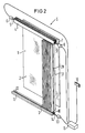
- a window 1 in the form of a pane, in front of which a slat curtain 2 with vertically oriented slats 3 is arranged on the inside of the room.
- a guide rail 4 is provided on the upper side of the window 1, which can be fastened in the usual way to a room ceiling, not shown, and in which a gear element (not shown here) is movably arranged for each lamella 3.
- a spindle 5 with an electric drive 6 is provided for moving the gear elements along the guide rail.
- the slats 3 themselves are fastened to the axes of rotation 9 of the gear elements assigned to them, which project vertically downward from the guide rail 4.
- a drive shaft 7 with an electric drive 8 is assigned to all the gear elements, by means of which the rotary position of the slats can be adjusted.
- a pipe rail 11 assigned to the guide rail 4 is provided with a longitudinal slot 12 on the top, into which guide pins 10 provided on the underside of the slats 3 engage.
- the guide pins 10 are arranged with their axis in the axis of rotation of the slats 3. Due to the ends of the guide pins 10 projecting into the longitudinal slot 12 of the tubular rail 11, the slats 3 can be adjusted and at the same time fixed in the closed state of the slat curtain 2 with regard to their desired positions.
- the adjusting fixing means which is arranged for this purpose in the pipe rail 11 and is to be described in more detail, is actuated by the electric drive 13 via the axis of rotation 14.
- the lamellae 3 made of light-refractive material with retroreflective properties, must each be oriented perpendicular to the plane of the sun rays S incident through the window 1 in order to be able to effectively reflect them.
- a control device 15 is provided for this purpose in conjunction with a stationary light sensor 16 adjusts the target rotational position of the slats 3 of the sun movement.
- the control device 15 also controls the opening and closing of the lamella process 2 via the electric drive 6 for the spindle 5 and the adjustment and fixing of the guide pins 10 via the electric drive 13.
- the control device 15 To open the lamella curtain 2 according to FIG. 1, the control device 15 first releases the fixation of the guide pins 10 in the tubular rail 11 via the electric drive 13. The slats 3 are then turned with their narrow side by the control device 15 via the electric drive 8 by approximately 90 ° into a position perpendicular to the direction of travel and then all the slats 3 are pushed together to the left by means of the spindle drive 5/6.
- Fig. 2 shows the lamella curtain 2 in the open end position.
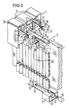
- the slats 3 on their smooth front side 37 facing the window 1 in the closed state of the slatted curtain have a stiffening rib 39 which is oriented parallel to their long sides and serves their torsional rigidity.
- the box-shaped gear elements 17 have flange-like projections 18 on the upper side on opposite sides, which are used to guide them in lateral grooves 34 of the guide rail 4. Furthermore, the gear elements 17 each have two mutually parallel slots 19 on their upper sides. One slot 19 of a pair of slots serves to rotatably mount a flat lever 21 anchored here in a pin 20. The other slot of a pair of slots, which is also bridged by the pin 20 is used to engage the free end of a flat lever 21, which is rotatably mounted on an adjacent gear element 17 in the pin 20 of one of its predetermined slots 19.
- Each gear element 17 for a lamella 3 represents a 90 ° deflection gear.
- This 90 ° deflection gear has a worm 22, which is aligned in its axis parallel to the axis of the guide rail and is designed as a hollow cylinder and which engages with a worm wheel anchored on the axis of rotation 9 23 stands.
- the drive shaft 7 common to all the gear elements 17 has a hexagonal profile here and is in engagement with the worm wheel 23 of all the gear elements 17.
- the gear element 17 shown in FIG. 3 is assigned to the first lamella 3 of the lamella curtain 2 and is in engagement with the spindle 5.
- a 1/3 threaded nut segment 24 is provided in the center on the upper side of the gear element 17.
- the spindle 5 itself, in order to prevent sagging over its length, is held in the guide rail 4 in a spindle bearing 25 which extends over the length of the guide rail 4 and which is a 2/3 bearing and can be, for example, a polyamide plastic part .
- the rectangular profile of the guide rail 4 has a web arrangement 26 which extends from above to the level of the lateral grooves 34.
- This web arrangement 26 consists of two mutually parallel inner webs 27, which are connected to one another at approximately half the height by a transverse web 28.
- a longitudinal web 29 continues to extend downward from the center of the transverse web 28, but ends above the free ends of the inner webs.
- the free ends of the inner webs 27 have a strip profile 30 on their opposite sides, which serves to hold the spindle bearing 25 inserted between the inner webs from below into the web arrangement 26.
- the guide rail On the top, has holding grooves 31 for its attachment, for example on a ceiling rail, and a lateral insertion groove 32.
- the slats 3 made of light-refracting material have a rear side, which consists of isosceles prisms 38 running alongside one another without gaps and parallel to the longitudinal sides of the slats. These prisms help align the slats 3 with its smooth front 37 perpendicular to the plane of incidence of the sun rays S totally reflects them.
- the axes of rotation 9 have at their lower edge a locking shoe 9 ', each comprising the stiffening rib 39 of a slat 3 at the upper edge and engaging in an undercut 39' of the stiffening rib.
- FIG. 3 there is a fixing rail 40 in the form of an angular rail in the tubular rail 11, which is connected to the electric drive 13 via the axis of rotation 14, in the upwardly oriented angular plate of which the desired positions of the guide pins 10 of the slats 3 with the slat curtain 2 closed Marking V-shaped slots 41 are embedded.
- the fixing rail 40 is folded forward by 90 °, the guide pins 10 of the slats 3 are both adjusted with respect to their desired position and fixed there.
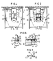
- FIG. 4 shows a preferred embodiment of the cross-sectional profile of the guide rail 4 with the lateral grooves 34 for guiding the gear elements 17 and the web arrangement 26.
- the 2/3 spindle bearing 25 is here molded directly onto the free ends of the longitudinal webs 27 and the inner web 29 , is therefore an integral part of the guide rail 4.
- the guide rail 4 for the passage of the axes of rotation 9 of the gear elements 17 has a continuous center slot 35.
- FIG. 4 shows an alternative to the 2/3 spindle bearing 25 corresponding to the embodiments according to FIGS. 3 and 4.
- this 2/3 spindle bearing 25 here in the web arrangement 26, specifically in the strip profile 30 Longitudinal webs 27 and in the free lower end of the inner web 29
- the driver coupling element 46 is rotatably mounted on the top of a spindle drag bearing 45 or 45 'in one of the slots 52 in a pin 51 and has a bore 50 for this purpose.
- a spring 49 engages the coupling hook arm, which the driver coupling element in a desired rotational position on the spindle drag bearing 45 or 45 'stops.
- the 1/1 threaded nut 24 used in this embodiment of the spindle holder in the guide rail 4 has a drive coupling pin 55 oriented perpendicular to the spindle axis, onto which the coupling hook with its front edge runs up when the threaded nut 24 approaches the spindle drag bearing 45 and finally by reaching behind it Driver coupling pin causes the desired coupling.
- the two spindle drag bearings are coupled to one another when the spindle drag bearing 45 approaches the spindle drag bearing 45 '.
- the drag bearings 45 and 45 'provided over the length of the guide rail are taken one behind the other when the lamella curtain is pulled up by the threaded nut 24 and combined with the threaded nut 24 to form a drag bearing assembly.
- this drag bearing assembly is by successively uncoupling the spindle drag bearings 45 and 45 'at the points where the stop fingers 48' and 48 of the driving coupling element 46 runs onto the stop pin 36 'or 36 assigned to it, dissolved again.
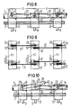
- FIGS. 8 and 9 three successive gear elements 17, which are connected to one another via flat levers 21, are shown in a side view and in a top view, as is the case when the lamella curtain 2 in FIG. 1 is closed.
- the top view in FIG. 9 shows that two flat levers 21 are rotatably mounted in journals 20 in one of two mutually adjacent slots 19 on the top of each gear element 17 at the same distance from the center. While in the gear element shown on the left, the flat levers 21, which are always aligned to the right, are each stored in the outer slot 19 of a pair of slots, the flat levers 21 are rotatably mounted in the pin 20 in the inner slot 19 of a pair of slots in the next gear element 17 following to the right.
- This sequence of pairs of flat levers in the manner of chain links of a bicycle chain makes it possible to use a pin 20 in each case simultaneously as a bearing of a flat lever at one end and as a counter bearing for another flat lever at its other end designed as a hook head 42.
- the flat levers 21 have at their free hook head end on the underside a sliding cam contour 21 '. Furthermore, they are connected on the side of their journal bearing with a spring 41, by means of which they are each braced downward against the journal 20 of the gear element 17 near them on the hook head side. How Fig. 10 reveals, the sliding cam contour 21 'of such a type that the flat levers 21 with their hook head 42 when pulling the slat curtain against the force of the spring 41 loosen from the pin 20 and lift up. When the slat curtain is closed, this process takes place in the opposite direction and ensures that the flat levers 21 are always securely caught in the pin 20 assigned to them.
- the distance A, with a slat width of 56 mm, is 57 mm.
Landscapes
- Engineering & Computer Science (AREA)
- Structural Engineering (AREA)
- Architecture (AREA)
- Civil Engineering (AREA)
- Blinds (AREA)
- Optical Elements Other Than Lenses (AREA)
- Operating, Guiding And Securing Of Roll- Type Closing Members (AREA)
- Curtains And Furnishings For Windows Or Doors (AREA)
Applications Claiming Priority (2)
| Application Number | Priority Date | Filing Date | Title |
|---|---|---|---|
| DE8805107U DE8805107U1 (de) | 1988-04-18 | 1988-04-18 | Sonnenschutzeinrichtung |
| DE8805107U | 1988-04-18 |
Publications (3)
| Publication Number | Publication Date |
|---|---|
| EP0338362A2 EP0338362A2 (de) | 1989-10-25 |
| EP0338362A3 EP0338362A3 (en) | 1990-08-01 |
| EP0338362B1 true EP0338362B1 (de) | 1992-12-09 |
Family
ID=6823062
Family Applications (1)
| Application Number | Title | Priority Date | Filing Date |
|---|---|---|---|
| EP89106276A Expired - Lifetime EP0338362B1 (de) | 1988-04-18 | 1989-04-10 | Sonnenschutzeinrichtung |
Country Status (4)
| Country | Link |
|---|---|
| US (1) | US4993469A (enExample) |
| EP (1) | EP0338362B1 (enExample) |
| JP (1) | JPH01162595U (enExample) |
| DE (2) | DE8805107U1 (enExample) |
Families Citing this family (32)
| Publication number | Priority date | Publication date | Assignee | Title |
|---|---|---|---|---|
| CA2111500A1 (en) * | 1992-12-22 | 1994-06-23 | Thomas J. Marusak | Vertical blind having honeycomb-shaped vanes |
| US5729103A (en) * | 1993-06-11 | 1998-03-17 | Harmonic Design, Inc. | Head rail-mounted actuator for window coverings |
| US5698958A (en) * | 1993-06-11 | 1997-12-16 | Harmonic Design, Inc. | Head rail-mounted actuator for window coverings |
| US6060852A (en) * | 1993-06-11 | 2000-05-09 | Harmonic Design, Inc. | Head rail-mounted actuator for window covering |
| US5524692A (en) * | 1994-03-07 | 1996-06-11 | Back Tracker, Inc. | Vertical blind retraction apparatus with spacing control |
| US5547008A (en) * | 1995-02-02 | 1996-08-20 | Sullivan; Kenneth J. | Mini blind and vertical blind actuator |
| US5611385A (en) * | 1996-01-29 | 1997-03-18 | Ching Feng Blinds Ind., Co., Ltd. | Distance adjusting structure for a vertical blind |
| US5793174A (en) * | 1996-09-06 | 1998-08-11 | Hunter Douglas Inc. | Electrically powered window covering assembly |
| US5765307A (en) * | 1996-09-20 | 1998-06-16 | Grimes; Ronald R. | Window blind systems |
| GB9710034D0 (en) * | 1997-05-16 | 1997-07-09 | Secretary Trade Ind Brit | Roller blind or curtain |
| SG79942A1 (en) * | 1997-05-20 | 2001-04-17 | Louver Shield Pty Ltd | Emergency release shutter assembly |
| DE10149449C1 (de) * | 2001-10-08 | 2002-11-14 | Bos Gmbh | Lamelle und daraus aufgebauter Lamellenvorhang |
| US7264034B2 (en) * | 2005-01-25 | 2007-09-04 | Ke-Min Lin | Motorized blind |
| US7650922B2 (en) * | 2006-09-14 | 2010-01-26 | Domenic Alberti | Window treatment for arch-shaped window |
| WO2011074862A2 (ko) * | 2009-12-15 | 2011-06-23 | Jung Taerok | 히트파이프형 유로 블라인드 |
| CZ2009846A3 (cs) * | 2009-12-15 | 2011-07-27 | Sehnoutek@Jan | Zarízení k využití solární energie |
| JP5521219B2 (ja) * | 2010-05-27 | 2014-06-11 | 大成建設株式会社 | ルーバー装置 |
| IT1404501B1 (it) * | 2011-02-25 | 2013-11-22 | Turina | Sistema mobile a fisarmonica di pannelli schermanti fotovoltaici a celle solari a colorante organico dssc per le facciate degli edifici preesistenti e di nuova costruzione |
| JP5914185B2 (ja) * | 2012-06-05 | 2016-05-11 | 立川ブラインド工業株式会社 | 縦型ブラインド及び振れ止め |
| JP2014001597A (ja) * | 2012-06-20 | 2014-01-09 | Tachikawa Blind Mfg Co Ltd | 縦型ブラインド |
| US8584730B1 (en) * | 2012-08-30 | 2013-11-19 | Grace F. Aderinto | Easy blinds |
| ES2460490B1 (es) * | 2012-11-13 | 2015-02-17 | Luis Prados Muñoz | Persiana con lamas multifunción de movimiento horizontal plegable |
| US9933761B2 (en) | 2012-11-30 | 2018-04-03 | Lutron Electronics Co., Inc. | Method of controlling a motorized window treatment |
| US10017985B2 (en) | 2013-08-14 | 2018-07-10 | Lutron Electronics Co., Inc. | Window treatment control using bright override |
| NL2013304C2 (nl) * | 2014-02-07 | 2015-08-10 | Solarswing Holding B V | Richtinrichting, zonnevolgsysteem en werkwijze daarvoor. |
| US20220257063A1 (en) * | 2014-10-31 | 2022-08-18 | Systems & Patents 2000, Sociedado Limitada | Enclosure system incorporating a cartridge assembly housing an extendable and retractable enclosure panel |
| WO2016199866A1 (ja) * | 2015-06-09 | 2016-12-15 | シャープ株式会社 | 採光装置、採光システム |
| JPWO2019054410A1 (ja) * | 2017-09-15 | 2020-10-22 | シャープ株式会社 | 採光装置 |
| CN108252639A (zh) * | 2017-12-18 | 2018-07-06 | 苏州市欧贝遮阳科技有限公司 | 自动化遮阳窗 |
| WO2020150755A1 (en) | 2019-01-17 | 2020-07-23 | Navus Consulting (Pty) Ltd | Transmission system for a blind |
| CN110644912A (zh) * | 2019-10-18 | 2020-01-03 | 杨小慧 | 一种适用于智能家居的多终端用户具有高度调节性的窗帘 |
| CN114809894A (zh) * | 2022-03-18 | 2022-07-29 | 绿城装饰工程集团有限公司 | 一种光伏遮阳一体板装置 |
Family Cites Families (15)
| Publication number | Priority date | Publication date | Assignee | Title |
|---|---|---|---|---|
| US2848045A (en) * | 1956-06-13 | 1958-08-19 | Dale L Bennett | Vertical venetian blind |
| US3134428A (en) * | 1960-01-18 | 1964-05-26 | Edgar K Orr | Louver-type window blind |
| US3054446A (en) * | 1960-06-30 | 1962-09-18 | Vertical Blinds Corp Of Americ | Vertical venetian blinds |
| CH410360A (de) * | 1962-07-20 | 1966-03-31 | Vertical Blinds Corp Of Americ | Jalousie mit um vertikalstehende Zapfen verschwenkbaren Lamellen |
| US3190346A (en) * | 1962-11-21 | 1965-06-22 | Verticals Inc | Vertical vane traverse mechanism |
| US3157223A (en) * | 1962-12-21 | 1964-11-17 | Verticals Inc | Vertical blinds |
| US3500896A (en) * | 1967-11-06 | 1970-03-17 | Yokota Kinzoku Kogyo Inc | Vertical venetian blinds |
| US3468360A (en) * | 1968-07-18 | 1969-09-23 | Harold A Payne | Venetian blind |
| US3646985A (en) * | 1970-04-13 | 1972-03-07 | Justin Huppe Kg | Venetian blind with automatic control of room brightness |
| US3789905A (en) * | 1971-08-22 | 1974-02-05 | Nichi Bei Blind Kogyo Kk | Vertical type venetian blind |
| US4350197A (en) * | 1978-08-03 | 1982-09-21 | Berthold Haller | Shutter blind assembly |
| ATE39724T1 (de) * | 1985-04-30 | 1989-01-15 | Siemens Ag | Sonnenschutzeinrichtung. |
| US4688618A (en) * | 1986-02-10 | 1987-08-25 | Saicheck Jr Harvey E | Carrier assembly for vertical blinds |
| US4841672A (en) * | 1986-07-04 | 1989-06-27 | Siemens Aktiengesellschaft | Device for protection from the sun |
| US4773464A (en) * | 1986-09-22 | 1988-09-27 | Kuron Corporation | Actuator for electric blinds |
-
1988
- 1988-04-18 DE DE8805107U patent/DE8805107U1/de not_active Expired
-
1989
- 1989-03-23 US US07/327,679 patent/US4993469A/en not_active Expired - Fee Related
- 1989-04-10 DE DE8989106276T patent/DE58902930D1/de not_active Expired - Fee Related
- 1989-04-10 EP EP89106276A patent/EP0338362B1/de not_active Expired - Lifetime
- 1989-04-18 JP JP1989044568U patent/JPH01162595U/ja active Pending
Also Published As
| Publication number | Publication date |
|---|---|
| EP0338362A2 (de) | 1989-10-25 |
| JPH01162595U (enExample) | 1989-11-13 |
| EP0338362A3 (en) | 1990-08-01 |
| US4993469A (en) | 1991-02-19 |
| DE58902930D1 (de) | 1993-01-21 |
| DE8805107U1 (de) | 1988-06-23 |
Similar Documents
| Publication | Publication Date | Title |
|---|---|---|
| EP0338362B1 (de) | Sonnenschutzeinrichtung | |
| EP0141805A2 (de) | Rolladen | |
| DE2729491A1 (de) | Streifenvorhang | |
| DE69513066T2 (de) | Zurückziehbare Store oder Jalousie | |
| CH653090A5 (de) | Rafflamellenstore. | |
| DE3345503A1 (de) | Rollo fuer fahrzeugscheiben | |
| DE4034614C3 (de) | Vorrichtung zum Verschatten von Fensterflächen | |
| DE69606561T2 (de) | Abschirmvorrichtung | |
| DE19525139A1 (de) | Vertikaljalousie mit einem Kurbelstab zur Betätigung | |
| CH653091A5 (de) | Rafflamellenstore. | |
| DE3225099C2 (enExample) | ||
| WO2017109165A1 (de) | Sonnenschutzsystem | |
| DE2452549B2 (de) | Lamellenjalousie | |
| DE4401056C1 (de) | Rolladen für ein Dachfenster | |
| EP1213439A2 (de) | Abdeckvorrichtung | |
| DE1810014C3 (de) | Lamellenvorhang | |
| CH677259A5 (enExample) | ||
| CH694436A5 (de) | Rolladen. | |
| EP0322355A1 (de) | Rafflamellenstore | |
| DE8516303U1 (de) | Jalousierbarer Rolladen | |
| DE3313467A1 (de) | Lamellen-laden | |
| DE3037703A1 (de) | Rafflamellenstore mit an den lamellenenden angeordneten fuehrungsgliedern | |
| CH653095A5 (en) | Gatherable lamellar blind with an arrangement for approximately horizontal alignment of the lowest lamella | |
| DE20005831U1 (de) | Rolladen für von der Rechteckform abweichende Formen von Gebäudeöffnungen | |
| DE1509807C3 (de) | Lamellenjalousie |
Legal Events
| Date | Code | Title | Description |
|---|---|---|---|
| PUAI | Public reference made under article 153(3) epc to a published international application that has entered the european phase |
Free format text: ORIGINAL CODE: 0009012 |
|
| AK | Designated contracting states |
Kind code of ref document: A2 Designated state(s): CH DE GB IT LI |
|
| PUAL | Search report despatched |
Free format text: ORIGINAL CODE: 0009013 |
|
| AK | Designated contracting states |
Kind code of ref document: A3 Designated state(s): CH DE GB IT LI |
|
| 17P | Request for examination filed |
Effective date: 19901205 |
|
| 17Q | First examination report despatched |
Effective date: 19911112 |
|
| GRAA | (expected) grant |
Free format text: ORIGINAL CODE: 0009210 |
|
| AK | Designated contracting states |
Kind code of ref document: B1 Designated state(s): CH DE GB IT LI |
|
| REF | Corresponds to: |
Ref document number: 58902930 Country of ref document: DE Date of ref document: 19930121 |
|
| ITF | It: translation for a ep patent filed | ||
| GBT | Gb: translation of ep patent filed (gb section 77(6)(a)/1977) |
Effective date: 19930215 |
|
| PLBE | No opposition filed within time limit |
Free format text: ORIGINAL CODE: 0009261 |
|
| 26N | No opposition filed | ||
| PGFP | Annual fee paid to national office [announced via postgrant information from national office to epo] |
Ref country code: DE Payment date: 19960620 Year of fee payment: 8 |
|
| PGFP | Annual fee paid to national office [announced via postgrant information from national office to epo] |
Ref country code: CH Payment date: 19960724 Year of fee payment: 8 |
|
| PGFP | Annual fee paid to national office [announced via postgrant information from national office to epo] |
Ref country code: GB Payment date: 19970321 Year of fee payment: 9 |
|
| PG25 | Lapsed in a contracting state [announced via postgrant information from national office to epo] |
Ref country code: LI Free format text: LAPSE BECAUSE OF NON-PAYMENT OF DUE FEES Effective date: 19970430 Ref country code: CH Free format text: LAPSE BECAUSE OF NON-PAYMENT OF DUE FEES Effective date: 19970430 |
|
| REG | Reference to a national code |
Ref country code: CH Ref legal event code: PL |
|
| PG25 | Lapsed in a contracting state [announced via postgrant information from national office to epo] |
Ref country code: DE Free format text: LAPSE BECAUSE OF NON-PAYMENT OF DUE FEES Effective date: 19980101 |
|
| PG25 | Lapsed in a contracting state [announced via postgrant information from national office to epo] |
Ref country code: GB Free format text: LAPSE BECAUSE OF NON-PAYMENT OF DUE FEES Effective date: 19980410 |
|
| GBPC | Gb: european patent ceased through non-payment of renewal fee |
Effective date: 19980410 |
|
| PG25 | Lapsed in a contracting state [announced via postgrant information from national office to epo] |
Ref country code: IT Free format text: LAPSE BECAUSE OF NON-PAYMENT OF DUE FEES;WARNING: LAPSES OF ITALIAN PATENTS WITH EFFECTIVE DATE BEFORE 2007 MAY HAVE OCCURRED AT ANY TIME BEFORE 2007. THE CORRECT EFFECTIVE DATE MAY BE DIFFERENT FROM THE ONE RECORDED. Effective date: 20050410 |
|
| PLAA | Information modified related to event that no opposition was filed |
Free format text: ORIGINAL CODE: 0009299DELT |
|
| PLBE | No opposition filed within time limit |
Free format text: ORIGINAL CODE: 0009261 |
|
| STAA | Information on the status of an ep patent application or granted ep patent |
Free format text: STATUS: NO OPPOSITION FILED WITHIN TIME LIMIT |
|
| D26N | No opposition filed (deleted) | ||
| RIN2 | Information on inventor provided after grant (corrected) |
Inventor name: SCHELER, WOLFRAM Inventor name: MITTELBACH, INGO Inventor name: MOENCH, JULIUS |
|
| 26N | No opposition filed |
Effective date: 19930910 |