EP0338301A1 - Dispositif d'alimentation en munitions - Google Patents
Dispositif d'alimentation en munitions Download PDFInfo
- Publication number
- EP0338301A1 EP0338301A1 EP89105760A EP89105760A EP0338301A1 EP 0338301 A1 EP0338301 A1 EP 0338301A1 EP 89105760 A EP89105760 A EP 89105760A EP 89105760 A EP89105760 A EP 89105760A EP 0338301 A1 EP0338301 A1 EP 0338301A1
- Authority
- EP
- European Patent Office
- Prior art keywords
- ammunition
- conveyor
- weapon
- feeder
- deflection
- Prior art date
- Legal status (The legal status is an assumption and is not a legal conclusion. Google has not performed a legal analysis and makes no representation as to the accuracy of the status listed.)
- Withdrawn
Links
Images


Classifications
-
- F—MECHANICAL ENGINEERING; LIGHTING; HEATING; WEAPONS; BLASTING
- F41—WEAPONS
- F41A—FUNCTIONAL FEATURES OR DETAILS COMMON TO BOTH SMALLARMS AND ORDNANCE, e.g. CANNONS; MOUNTINGS FOR SMALLARMS OR ORDNANCE
- F41A9/00—Feeding or loading of ammunition; Magazines; Guiding means for the extracting of cartridges
- F41A9/37—Feeding two or more kinds of ammunition to the same gun; Feeding from two sides
-
- F—MECHANICAL ENGINEERING; LIGHTING; HEATING; WEAPONS; BLASTING
- F41—WEAPONS
- F41A—FUNCTIONAL FEATURES OR DETAILS COMMON TO BOTH SMALLARMS AND ORDNANCE, e.g. CANNONS; MOUNTINGS FOR SMALLARMS OR ORDNANCE
- F41A9/00—Feeding or loading of ammunition; Magazines; Guiding means for the extracting of cartridges
- F41A9/01—Feeding of unbelted ammunition
- F41A9/04—Feeding of unbelted ammunition using endless-chain belts carrying a plurality of ammunition
Definitions
- the invention relates to a device for feeding the ammunition to a weapon arranged in the turret of a combat vehicle by means of an elevator, which extends from a ring magazine arranged near the ground to an ammunition feeder on the weapon.
- the ammunition has so far been supplied in such a way that the elevator arranged between a ring magazine arranged near the ground and the feeder of the weapon has a strand which is guided directly from the ring magazine to the weapon.
- the elevator is driven in cycles according to the cadence of the weapon. With each work cycle, a projectile is delivered to the feeder and a projectile is removed from the ring magazine.
- the elevator and the ring magazine must therefore be clocked, accelerated and decelerated with each shot.
- an ammunition buffer in the form of a loop had to be provided between the ring magazine and the elevator.
- the invention has for its object to design a device of the aforementioned construction so that the maximum cadence of the weapon can be exploited while reducing the drive and deceleration forces to be applied in the ammunition conveyor circuit.
- the elevator is designed as an endless circulating conveyor, which is deflected near the ring magazine on a horizontal and near the feeder on a substantially parallel to the weapon, the elevation movement of the weapon following axis and one in the area of the upper deflection the feeder has a common position for the transfer and in the area of the lower deflection has a position for taking over the ammunition with the ring magazine or with a conveyor which removes the ammunition from it.
- the ring magazine is arranged on the tower platform, so that the circulating conveyor bridges the height between the ring magazine and the weapon or feeder.
- the circulation conveyor picks up the ammunition from the ring magazine at the take-over position. It can be ammunitioned from the ring magazine before the battle or during pauses in the battle, so that all positions of the circulation conveyor are occupied by one projectile. In the combat state, the projectiles are delivered from the circulation conveyor to the feeder.
- the circulation conveyor is decoupled from the ring magazine, so that only the circulation conveyor can be accelerated and decelerated in battle according to the cadence.
- the circulation conveyor follows every elevation of the weapon.
- the circulation conveyor expediently has at least as many receiving positions as ammunition is necessary for a combat task, so that the circulation conveyor is completely or partially emptied during the battle.
- the empty positions can then be ammunitioned during a battle break.
- a rotary conveyor is arranged on each side of the vertical plane enclosing the core axis of the weapon.
- each circulation conveyor can be driven in opposite directions, so that it rotates in the opposite direction, for example, for ammunition or re-ammunition as in battle.
- each circulating conveyor has an endless belt receiving the ammunition in open shells, driven by a deflection axis, the belt members of which each have a shell and are connected to one another in an articulated manner and with play, and one the ammunition at their Shell outer surface leading outer shell following the elevation movement of the weapon has, and that the belt is guided on a resilient spring strand which runs over the deflection axes.
- the belt Due to the all-round articulated and playful connection of the belt members with the shells for receiving the ammunition, the belt can be guided in a narrow orbit and follow the elevation of the weapon. The same applies to the spring strand guiding the belt, which due to its flexibility can be compressed and stretched and at the same time ensures safe guidance of the belt along the entire movement path.
- the drive takes place from a deflection axis, for example by having drive elements engaging between the belt members.
- the open design of the belt shells which allows easy transfer and transfer of the ammunition, requires guidance of the ammunition in its orbit on its free outer surface, which is done by the outer guide surface, which must also be designed so that it follows the elevation movement of the weapon .
- the spring strand is advantageously a helical spring on which the belt members are guided by means of sliding pieces.
- the sliders which are advantageously arranged in the form of a three-point bearing, are preferably of spherical design in order to allow the least possible friction with the helical spring and thus the greatest possible freedom of movement of the spring windings.
- each circulation conveyor has an inner guide surface which supports the belt or the spring strand and follows the elevation movement of the weapon on its inner side opposite the ammunition associated with the ammunition.
- the outer and inner guide surfaces are, for example formed in two parts. One part is connected to the upper deflection axis, which follows the movement of the weapon, the other part to the ring magazine.
- the two guide surface parts overlap on part of the guide length and lie in one plane in the overlap area.
- the guide surfaces can be formed by strips that overlap one another or walls that intermesh like a comb in the overlap region.
- a partially circular slide closure is arranged at the take-over position of the circulation conveyor on the ring magazine, which allows the ammunition to be taken over in the open position and leads the ammunition in the region of the deflection on the casing side in the closed position.
- the circulation conveyor In the open position of the partially circular slide closure, the circulation conveyor is ammunitioned or the ammunition is fed directly from the ring magazine into the feeder, while in the closed position, the circulation conveyor is fired at.
- the conveyor taking the ammunition out of the ring magazine is designed as an elevator with the grippers receiving the ammunition and can be driven in opposite directions and on both sides of its upper deflection has a takeover position common to each of a circulation conveyor.
- a flap for manual ammunition of the circulating conveyors is advantageously arranged on the outer guide surfaces near the lower deflection of each circulating conveyor.
- each circulating conveyor can be driven in opposite directions enables on the one hand the filling of the circulating conveyor from the ring magazine, and on the other hand also the release of the ammunition from the circulating conveyor into the ring magazine.
- the circulation conveyor can also serve to fill up the ring magazine.
- the feeder has two star wheels for the ammunition rotating around parallel axes, and that a deflecting element which can be pivoted into the orbit of the ammunition of the circulation conveyor and which transfers the ammunition from a bowl of the circulation conveyor into the star wheel is arranged at the transfer position.
- the deflection elements direct the ammunition from the shells of the circulation conveyor directly into the feeder.
- the deflecting member By swiveling the deflecting member, it can be brought into a position in which it guides the ammunition located in the circulation conveyor on the exposed lateral surface. This position is set in particular when ammunitioning or re-ammunition of the circulating conveyor, so that the shells or the ammunition lying in them is guided past the transfer position at the feeder.
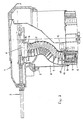
- FIGs 1 and 2 of a combat vehicle only the tower 1 is shown, which is rotatably mounted in the ceiling of the vehicle via a bearing ring 2.
- the weapon 3 and a ring magazine 5, in which the ammunition 6 is inserted in several rows one above the other, are arranged below the ceiling of the tower 1 and on the tower platform 4.
- An elevator 8 extends between the ring magazine 5 and a feeder 7 arranged on the weapon 3 and transports the ammunition from the ring magazine into the feeder.
- the elevator 8 consists of two side-by-side, endless circulating conveyors 9, the strand of which is designed in the manner of a belt which is deflected via lower axes 10 with star wheels and upper axes 11 with star wheels.
- the lower star wheels or their axes 10 are driven by a motor 12 (FIG. 2) with a horizontal axis.
- the upper deflection axes 10 of the circulation conveyor 9 are operatively connected to the feeder in such a way that they follow the elevation movements of the weapon 3.
- Each circulation conveyor 9 has a take-over position 13 in the region of the lower deflection and a transfer position 14 in the region of the upper deflection, these positions being arranged on the mutually facing regions of the deflection.
- An endless conveyor 15 in the form of an elevator with grippers 16 for receiving the ammunition 6 is arranged within the ring magazine.
- a position of the ammunition 6 can be raised from the ring magazine into the area of the takeover position 13 of the circulating conveyor 9.
- a closure 17 is arranged, which releases the take-over position in the open position (see left circulation conveyor in FIG. 1), while it covers the take-over position in the closed position (right circulation conveyor in FIG. 1).
- a deflector 19 is arranged in each case, which, from the position shown in the right circulating conveyor 9, in which it transfers the ammunition from the circulating conveyor into the feeder, into one the position shown on the left-hand circulating conveyor can be swung out, in which it is the Covering the transfer position and the ammunition 6 located in the circulation conveyor 9 on the outer lateral surface.
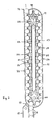
- Each circulating conveyor 9 has a kind of belt 20 as the conveying member (see FIG. 3), the belt members of which each have a shell 21 for receiving one storey each.
- the belt 20 is driven by the motor 12, on the axis 10 of which a star wheel engages in the belt.
- the shells are open to the outside, so that they only carry the ammunition on one side.
- outer guide surfaces 22 are provided which approximately follow the contour of the circulation conveyor.
- inner guide surfaces 23 for the belt 20 are provided on the inside of the belt 20.
- the guide surfaces 22 have an opening in the area of the take-over position 13 on the elevator 15 of the ring magazine and on the transfer station 14 in the area of the feeder 7, which, as already mentioned, can be at least partially covered by the closing slide 17 or the deflection members 19.
- the guide surfaces 22 and 23 can each be formed in two parts and overlap in the region 24 in a tooth-like or comb-like manner, so that the upper part with the deflection axes 11 can follow the elevation movement of the weapon 3.
- a flexible spring strand in the form of a helical spring 28 serves as a guide member for the belt 20, which always ensures undisturbed guidance of the belt 20 by a resilient design regardless of the elevation of the weapon.
- the individual belt members 25, as can be seen in particular from FIGS. 4 and 6, are guided on the coil spring 28 by means of three sliding pieces 29 and 30, the sliding pieces 29, 30 having a curved sliding surface in order to ensure reliable guidance despite the uneven surface of the coil spring 28 to ensure the greatest possible freedom of movement of the coil spring 28.
- the shells 21 can have an annular bead 31 on one end face, which exerts a certain clamping force on the inserted ammunition.
- the device works as follows:
- each circulating conveyor - depending on the direction of rotation of the elevator 15 - can be ammunition, during which the deflection element 19 in the area of the feeder 7 is swung out into the position shown in the left-hand circulating conveyor in FIG. 1, so that it is in the area of the transfer position 14 incoming bullets are guided past the feeder.
- an empty round conveyor can be ammunitioned or an only partially empty round conveyor can be re-ammunition by clocking the empty positions into the takeover position 14.
- the circulation conveyor 9 is ready for battle.
- the deflection member 19 is pivoted into the position shown on the right, so that the ammunition is released at the transfer position 14 to one of the star wheels 18 of the feeder 7 as the circulation conveyor 9 continues to rotate. If necessary, two different types of ammunition can be stored in the ring magazine and the same type of ammunition can be transferred to one or the other circulation conveyor will be given, so that one or the other ammunition can be provided on the weapon.
- the outer guide surface 22 has a swing-out flap 32, via which the circulation conveyor 9 can be loaded manually, be it to manually ammunition it itself or to store ammunition from the vehicle via the circulation conveyor in the ring magazine 5.
Landscapes
- Engineering & Computer Science (AREA)
- General Engineering & Computer Science (AREA)
- Specific Conveyance Elements (AREA)
- Warehouses Or Storage Devices (AREA)
Applications Claiming Priority (2)
| Application Number | Priority Date | Filing Date | Title |
|---|---|---|---|
| DE19883812696 DE3812696A1 (de) | 1988-04-16 | 1988-04-16 | Vorrichtung zur munitionszufuehrung |
| DE3812696 | 1988-04-16 |
Publications (1)
| Publication Number | Publication Date |
|---|---|
| EP0338301A1 true EP0338301A1 (fr) | 1989-10-25 |
Family
ID=6352123
Family Applications (1)
| Application Number | Title | Priority Date | Filing Date |
|---|---|---|---|
| EP89105760A Withdrawn EP0338301A1 (fr) | 1988-04-16 | 1989-04-01 | Dispositif d'alimentation en munitions |
Country Status (2)
| Country | Link |
|---|---|
| EP (1) | EP0338301A1 (fr) |
| DE (1) | DE3812696A1 (fr) |
Cited By (5)
| Publication number | Priority date | Publication date | Assignee | Title |
|---|---|---|---|---|
| FR2715463A1 (fr) * | 1994-01-21 | 1995-07-28 | Giat Ind Sa | Système d'alimentation en munitions pour une arme à feu de moyen calibre. |
| US5675110A (en) * | 1994-07-22 | 1997-10-07 | Cta International | Dual ammunition feeding system for a fire arm and method for feeding different ammunition types using a common transfer mechanism |
| FR2755223A1 (fr) * | 1996-10-26 | 1998-05-01 | Rheinmetall Ind Ag | Tourelle protegee pour vehicules blindes |
| CN114641665A (zh) * | 2019-10-15 | 2022-06-17 | 贝以系统哈格伦斯公司 | 用于向武器供给弹药的设备 |
| WO2023229543A1 (fr) * | 2022-05-24 | 2023-11-30 | Tasyagan Abdullah Oguz | Configuration de chargeur de sangle |
Families Citing this family (1)
| Publication number | Priority date | Publication date | Assignee | Title |
|---|---|---|---|---|
| IL258680A (en) * | 2018-04-12 | 2018-05-31 | Atias Eliran | Ammunition storage and feed system |
Citations (6)
| Publication number | Priority date | Publication date | Assignee | Title |
|---|---|---|---|---|
| US1332060A (en) * | 1918-10-15 | 1920-02-24 | Pacilli Leonardo | Recoll-operated ordnance |
| GB583360A (en) * | 1938-12-10 | 1940-11-25 | Archibald Goodman Frazer Nash | Improvements in and relating to means for supplying ammunition to guns |
| FR2135681A5 (fr) * | 1968-09-03 | 1972-12-22 | Rheinstahl Henschel Ag | |
| US4363397A (en) * | 1981-02-27 | 1982-12-14 | The United States Of America As Represented By The Secretary Of The Army | Z-Transfer device for ammunition |
| DE3342223A1 (de) * | 1982-11-26 | 1984-05-30 | Heckler & Koch Gmbh, 7238 Oberndorf | Patronenzufuehrvorrichtung |
| EP0152549A1 (fr) * | 1983-12-22 | 1985-08-28 | Werkzeugmaschinenfabrik Oerlikon-Bührle AG | Dispositif d'alimentation d'armes à feu en munitions |
-
1988
- 1988-04-16 DE DE19883812696 patent/DE3812696A1/de not_active Withdrawn
-
1989
- 1989-04-01 EP EP89105760A patent/EP0338301A1/fr not_active Withdrawn
Patent Citations (6)
| Publication number | Priority date | Publication date | Assignee | Title |
|---|---|---|---|---|
| US1332060A (en) * | 1918-10-15 | 1920-02-24 | Pacilli Leonardo | Recoll-operated ordnance |
| GB583360A (en) * | 1938-12-10 | 1940-11-25 | Archibald Goodman Frazer Nash | Improvements in and relating to means for supplying ammunition to guns |
| FR2135681A5 (fr) * | 1968-09-03 | 1972-12-22 | Rheinstahl Henschel Ag | |
| US4363397A (en) * | 1981-02-27 | 1982-12-14 | The United States Of America As Represented By The Secretary Of The Army | Z-Transfer device for ammunition |
| DE3342223A1 (de) * | 1982-11-26 | 1984-05-30 | Heckler & Koch Gmbh, 7238 Oberndorf | Patronenzufuehrvorrichtung |
| EP0152549A1 (fr) * | 1983-12-22 | 1985-08-28 | Werkzeugmaschinenfabrik Oerlikon-Bührle AG | Dispositif d'alimentation d'armes à feu en munitions |
Cited By (8)
| Publication number | Priority date | Publication date | Assignee | Title |
|---|---|---|---|---|
| FR2715463A1 (fr) * | 1994-01-21 | 1995-07-28 | Giat Ind Sa | Système d'alimentation en munitions pour une arme à feu de moyen calibre. |
| US5571984A (en) * | 1994-01-21 | 1996-11-05 | Giat Industries | Ammunition feed system for a medium-calibre firearm |
| US5675110A (en) * | 1994-07-22 | 1997-10-07 | Cta International | Dual ammunition feeding system for a fire arm and method for feeding different ammunition types using a common transfer mechanism |
| FR2755223A1 (fr) * | 1996-10-26 | 1998-05-01 | Rheinmetall Ind Ag | Tourelle protegee pour vehicules blindes |
| US5880395A (en) * | 1996-10-26 | 1999-03-09 | Rheinmetall Industrie Ag | Gun turret assembly for an armored vehicle |
| CN114641665A (zh) * | 2019-10-15 | 2022-06-17 | 贝以系统哈格伦斯公司 | 用于向武器供给弹药的设备 |
| CN114641665B (zh) * | 2019-10-15 | 2024-02-27 | 贝以系统哈格伦斯公司 | 用于向武器供给弹药的设备 |
| WO2023229543A1 (fr) * | 2022-05-24 | 2023-11-30 | Tasyagan Abdullah Oguz | Configuration de chargeur de sangle |
Also Published As
| Publication number | Publication date |
|---|---|
| DE3812696A1 (de) | 1989-11-02 |
Similar Documents
| Publication | Publication Date | Title |
|---|---|---|
| DE69834290T2 (de) | Motorangetriebener Paintballzuführmechanismus | |
| DE2222789C2 (de) | Munitionsbeschickungsvorrichtung für eine in einem Flugzeug angeordnete automatische Waffe | |
| DE2501425C2 (de) | Geschoßzuführungsvorrichtung an einem waffentragenden Fahrzeug | |
| DE3807474A1 (de) | Kampffahrzeug, insbesondere panzerhaubitze | |
| CH636190A5 (de) | Vorrichtung fuer den munitionstransport aus einem magazin in eine mit der seelenachse des geschuetzrohres koaxiale ladeposition. | |
| EP0022286A1 (fr) | Dispositif de chargement pour véhicule blindé | |
| EP0178484A1 (fr) | Chargeur pour canons | |
| EP0405177A1 (fr) | Dispositif d'alimentation en cartouches d'une arme à feu se déplaçant en azimut | |
| DE2501424C2 (de) | Munitionsaufnahme- und Ladevorrichtung für eine großkalibrige Feuerwaffe | |
| DE3702603C2 (fr) | ||
| DE69916498T2 (de) | Ladungssystem | |
| DE3642920C2 (de) | Ladevorrichtung für ein Kampffahrzeug, insbesondere eine Panzerhaubitze | |
| WO2004055464A1 (fr) | Module de tir | |
| DE665087C (de) | Munitionsmagazin fuer Handfeuerwaffen | |
| EP0338301A1 (fr) | Dispositif d'alimentation en munitions | |
| EP0361050B1 (fr) | Convoyeur à chaîne sans fin pour chargeur de munitions | |
| EP0231493A1 (fr) | Transporteur à maillons pour l'alimentation en cartouches d'une arme à feu automatique | |
| EP0277478A1 (fr) | Char de combat | |
| EP0754926A2 (fr) | Tourelle pour un véhicule à roues ou à chenilles | |
| EP0184008B1 (fr) | Dispositif de surveillance de mise à feu à retardement pour canon à moteur externe | |
| DE3510308C2 (fr) | ||
| DE3612208A1 (de) | Vorrichtung zum laden einer panzerwaffe | |
| DE3020482A1 (de) | Einrichtung zum automatischen ueberfuehren von geschossen | |
| DE2852704C1 (de) | Munitionstransportvorrichtung fuer ein scheitellafettiertes Geschuetz | |
| EP0111780B1 (fr) | Dispositif pour le transport de munitions à partir d'un magasin à tambour vers un canon |
Legal Events
| Date | Code | Title | Description |
|---|---|---|---|
| PUAI | Public reference made under article 153(3) epc to a published international application that has entered the european phase |
Free format text: ORIGINAL CODE: 0009012 |
|
| AK | Designated contracting states |
Kind code of ref document: A1 Designated state(s): AT BE CH DE ES FR GB GR IT LI LU NL SE |
|
| 17P | Request for examination filed |
Effective date: 19900409 |
|
| 17Q | First examination report despatched |
Effective date: 19910731 |
|
| STAA | Information on the status of an ep patent application or granted ep patent |
Free format text: STATUS: THE APPLICATION IS DEEMED TO BE WITHDRAWN |
|
| 18D | Application deemed to be withdrawn |
Effective date: 19911211 |