EP0337703A2 - Akustisches Oberflächenwellenfilter - Google Patents
Akustisches Oberflächenwellenfilter Download PDFInfo
- Publication number
- EP0337703A2 EP0337703A2 EP89303519A EP89303519A EP0337703A2 EP 0337703 A2 EP0337703 A2 EP 0337703A2 EP 89303519 A EP89303519 A EP 89303519A EP 89303519 A EP89303519 A EP 89303519A EP 0337703 A2 EP0337703 A2 EP 0337703A2
- Authority
- EP
- European Patent Office
- Prior art keywords
- saw
- filter
- resonator
- set forth
- electrode fingers
- Prior art date
- Legal status (The legal status is an assumption and is not a legal conclusion. Google has not performed a legal analysis and makes no representation as to the accuracy of the status listed.)
- Granted
Links
Images


Classifications
-
- H—ELECTRICITY
- H03—ELECTRONIC CIRCUITRY
- H03H—IMPEDANCE NETWORKS, e.g. RESONANT CIRCUITS; RESONATORS
- H03H9/00—Networks comprising electromechanical or electro-acoustic devices; Electromechanical resonators
- H03H9/46—Filters
- H03H9/64—Filters using surface acoustic waves
- H03H9/6423—Means for obtaining a particular transfer characteristic
- H03H9/6433—Coupled resonator filters
- H03H9/6483—Ladder SAW filters
-
- H—ELECTRICITY
- H03—ELECTRONIC CIRCUITRY
- H03H—IMPEDANCE NETWORKS, e.g. RESONANT CIRCUITS; RESONATORS
- H03H9/00—Networks comprising electromechanical or electro-acoustic devices; Electromechanical resonators
- H03H9/02—Details
- H03H9/02535—Details of surface acoustic wave devices
- H03H9/02637—Details concerning reflective or coupling arrays
- H03H9/02685—Grating lines having particular arrangements
- H03H9/0274—Intra-transducers grating lines
- H03H9/02755—Meandering floating or grounded grating lines
-
- H—ELECTRICITY
- H03—ELECTRONIC CIRCUITRY
- H03H—IMPEDANCE NETWORKS, e.g. RESONANT CIRCUITS; RESONATORS
- H03H9/00—Networks comprising electromechanical or electro-acoustic devices; Electromechanical resonators
- H03H9/46—Filters
- H03H9/64—Filters using surface acoustic waves
- H03H9/6423—Means for obtaining a particular transfer characteristic
- H03H9/6433—Coupled resonator filters
- H03H9/644—Coupled resonator filters having two acoustic tracks
- H03H9/6456—Coupled resonator filters having two acoustic tracks being electrically coupled
- H03H9/6459—Coupled resonator filters having two acoustic tracks being electrically coupled via one connecting electrode
- H03H9/6463—Coupled resonator filters having two acoustic tracks being electrically coupled via one connecting electrode the tracks being electrically cascaded
-
- H—ELECTRICITY
- H03—ELECTRONIC CIRCUITRY
- H03H—IMPEDANCE NETWORKS, e.g. RESONANT CIRCUITS; RESONATORS
- H03H9/00—Networks comprising electromechanical or electro-acoustic devices; Electromechanical resonators
- H03H9/46—Filters
- H03H9/64—Filters using surface acoustic waves
- H03H9/6423—Means for obtaining a particular transfer characteristic
- H03H9/6433—Coupled resonator filters
- H03H9/6479—Capacitively coupled SAW resonator filters
-
- H—ELECTRICITY
- H03—ELECTRONIC CIRCUITRY
- H03H—IMPEDANCE NETWORKS, e.g. RESONANT CIRCUITS; RESONATORS
- H03H9/00—Networks comprising electromechanical or electro-acoustic devices; Electromechanical resonators
- H03H9/02—Details
- H03H9/02535—Details of surface acoustic wave devices
- H03H9/02818—Means for compensation or elimination of undesirable effects
- H03H9/02921—Measures for preventing electric discharge due to pyroelectricity
Definitions
- the present invention relates to a filter which utilizes a surface acoustic wave (SAW), and more particularly to a SAW filter which is well suited to transmitters and receivers for mobile communications, especially for cellular radio.
- SAW filter according to the present invention is applied to mobile communication equipments such as a pocket bell, mobile telephone and cordless telephone.
- a conventional SAW filter of the so-called transversal type has had a construction wherein an input interdigital transducer for converting an electric signal into a surface acoustic wave, and an output interdigital transducer for inverting the surface acoustic wave into an electric signal again are arranged on a piezoelectric substrate.
- An example of the SAW filter is stated in, e. g., Proceedings of IEEE, Vol. 67 (1979), pp. 129-146. '
- the principal object of the present invention is to provide an improved SAW filter which solves the technical themes mentioned before.
- a more concrete object of the present invention is to provide a SAW filter which has novel frequency characteristics.
- a SAW filter comprising a plurality of SAW resonators, at least one of which is said SAW resonator having said plurality of SAW transmission spaces.
- a SAW filter wherein among said plurality of SAW resonators, one located on an electric power input side is said SAW resonator having said plurality of SAW transmission spaces.
- a SAW filter comprising a first SAW resonator which is disposed on an electric power input side, and a second SAW resonator which is disposed on an electric power output side, wherein at least one of said SAW resonators is said SAW resonator having said plurality of SAW transmission spaces, and said SAW resonators are electrically connected in series with each other.
- a SAW filter wherein said first and second SAW resonators are electrically connected through a capacitor.
- a gap capacitor is available. Owing to the presence of the capacitor, an attenuation value outside a band can be remarkably increased.
- a SAW filter comprising a third SAW resonator which is connected in cascade with said first SAW resonator or said second SAW resonator as viewed from the input side or output side of said filter.
- the third SAW resonator enlarges the attenuation value of a lower frequency side in the frequency characteristics of the SAW filter.
- a SAW filter wherein the third SAW resonators are respectively disposed on said input side and said output side.
- a SAW filter wherein said SAW resonator having said plurality of SAW transmission spaces includes a third electrode pattern which has a plurality of electrode fingers electrically connected in common, said electrode fingers being respectively interleaved between said first electrode pattern which has the plurality of electrically connected electrode fingers and said second electrode pattern which has the plurality of electrically connected electrode fingers.
- This SAW filter is effective especially as a high impedance filter.
- a SAW filter wherein at least one further SAW resonator is connected electrically in series between said first SAW resonator and said second SAW resonator.
- Such a SAW resonator increases the attenuation value of the higher frequency side of the frequency characteristics of the SAW filter.
- the SAW resonator has still another SAW resonator connected in cascade therewith, the attenuation value of the lower frequency side can be simultaneously increased.
- a SAW filter comprising a SAW resonator including a piezoelectric substrate, and a plurality of SAW excitation portions which are configured of a plurality of pairs of electrode fingers formed on said piezoelectric substrate, said respective SAW excitation portions being spacedly arranged so that phases of SAW excited by them may come into agreement.
- the spacing between the respectively adjacent excitation portions is given by 2m + 1 2 X or nX , depending upon how to construct the SAW resonator.
- the plurality of electrode fingers of the SAW excitation portion are disposed at intervals of ⁇ /2. It is accordingly important that the spacing (electric length) between the SAW excitation portions is greater than x / 2.
- One advantage of the present invention is that a SAW filter having abrupt lower and upper cutoff frequency characteristics can be realized.
- Another advantage of the present invention is that a SAW filter with a structure easy of realizing desired frequency characteristics which are not uniquely determined by the piezoelectric characteristics of a substrate can be realized.
- Fig. 1 is an arrangement diagram of one embodiment of the filter of the present invention.
- the embodiment is an example in which a combined resonator filter is formed in such a way that four one-port SAW (surface acoustic wave) resonators configured of metal electrodes 4-1, 4-2, 4-3, 4-4, 4-5 and 4-6 and a single gap capacitor configured of electrode patterns 5-1 and 5-2 are provided on a piezoelectric substrate 7 capable of transmitting a SAW.
- Symbols 1 and 1 denote terminals for an electric power input, while symbols 2 and 2 denote terminals for an electric power output.
- each of the resonators is constructed of an interdigital transducer which is made up of a large number of pairs of metal electrode fingers interleaved to one another.
- FIG. 3A The electrical equivalent circuit of such a one-port SAW resonator (Fig. 3A) is as shown in Fig. 3B.
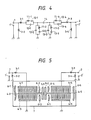
- the filter in Fig. 1 is given by an equivalent circuit shown in Fig. 4, that is, an equivalent circuit arranged such that a series arm resonator which consists of an equivalent inductance 11-1, an equivalent capacitance 12-1 and a capacitance 13-1, and a shunt arm resonator which consists of an equivalent inductance 11-2, an equivalent capacitance 12-2 and a capacitance 13-2, the series and shunt arm resonators being connected in cascade as viewed from the input side, is connected through a gap capacitor 14 with a series arm resonator which consists of an equivalent inductance 11-4, an equivalent capacitance 12-4 and ' a capacitance 13-4, and a shunt arm resonator which consists of an equivalent inductance 11-3, an equivalent capacitance 12-3 and a capacitance 13-3, the
- each of the series arm resonator and shunt arm resonator on the input side includes therein a plurality of transmission spaces each having an electric length not less than the wavelength of a SAW which can be transmitted at the pass-band frequency of the filter. (By the way, in Figs. 1 and 4, inductances 3-1, 3-2, 3-3 and 3-4 indicate external matching circuits.)
- Fig. 5 shows another example of arrangement of a combined resonator filter which has been proposed by the inventors.
- both a series arm resonator and a shunt arm resonator on an input side are constructed of interdigital transducers each being configured of simple electrode fingers in a large number of pairs, similarly to resonators on an output side.
- the resonators on the output sides are the same, but the electrode constructions of the series arm resonators and shunt arm resonators on the input sides are different.
- the filter of the arrangement in Fig. 1 the filter of the arrangement in Fig.
- a SAW filter need not always be constructed of a plurality of SAW resonators.
- the filter may well be constructed of one series arm resonator and one shunt arm resonator. Increases in the number of series arm resonators and the number of shunt arm resonators result in enlarging attenuation values on a higher frequency side and a lower frequency side, respectively.
- it is a favorable aspect to include at least two series arm resonators and at least two shunt arm resonators. In an extreme case, even a SAW filter constructed of only one SAW resonator can be realized.
- Figs. 6A and 6B results obtained by simulating frequency characteristics with a computer as to the filter of the arrangement in Fig. 1 and the filter of the. arrangement in Fig. 5 are illustrated in Figs. 6A and 6B.
- Fig. 6A shows the frequency characteristics. of the filter based on the arrangement of the present invention in Fig. 1
- Fig. 6B shows the frequency characteristics of the filter based on the arrangement in Fig. 5.
- poles f 1 ', f 2 ' on a lower frequency side and poles f 3 ', f 4 ' on a higher frequency side are respectively existent also in Fig. 6B, in correspondence with poles f,, f 2 on a lower frequency side and poles f 3 , f 4 . on a higher frequency side in Fig. 6A.
- f 2 > fz and f 3 ⁇ f3' hold In general, the realization of abrupt lower and upper cutoff frequency characteristics is determined by the extent to which the poles nearest to ihe pass band (the poles f 2 , f 3 in Fig.
- the pole f 2 close to the pass band on the lower frequency side in Fig. 6A is formed by the shunt arm resonator of the input side in Fig. 1 (corresponding to the elements 11-2, 12-2 and 13-2 of the equivalent circuit in Fig. 4). That is, the resonant frequency of the shunt arm resonator agrees with the pole f 2 .
- the pole f 3 close to the pass band on the higher frequency side in Fig. 6A is formed by the series arm resonator in Fig.
- poles f2 and f3 close to the pass band agree with the resonant frequency of the shunt arm resonator and the antiresonant frequency of the series arm resonator of the input side in Fig. 5, respectively, while the other poles f, and f 4 ' agree with the resonant frequency of the shunt arm resonator and the antiresonant frequency of the series arm resonator of the output side, respectively.
- the differences between the filter of the arrangement in Fig. 1 and the filter of the arrangement in Fig. 5 lie in the different constructions of the series arm resonators and shunt arm resonators of the input sides. More specifically, the characterizing feature of the filter of the arrangement of the present invention in Fig. 1 is that the plurality of transmission spaces each having the electric length not less than the wavelength of the SAW which can travel at the pass-band frequency of the filter are included within the one-port SAW resonator. Owing to the use of the one-port SAW resonators of such construction, even when the corresponding poles f 2 and f 3 in Fig.
- the electric length of the SAW transmission space as stated above is given by nx.
- n denotes an integer of at least one
- ⁇ denotes the wavelength of the SAW which is excited in correspondence with the center wavelength of the pass-band frequencies of the filter.
- Essential is that such SAW transmission spaces have electric lengths which match the phases of SAWs to be excited, in other words, electric lengths which transmit the SAWs while keeping the phases.
- the length of each SAW transmission space is ⁇ (where m denotes an integer of at least one).
- the electric length may be approximately equal to nX (or ⁇ ), and n( ⁇ ) (or ( ⁇ )) is available within a range of 0 ⁇ ⁇ 0.2.
- nX or ⁇
- n( ⁇ ) or ( ⁇ )
- the one-port SAW resonators of the conventional structure are employed on the input side as in the arrangement of Fig. 5, even when the corresponding poles f2 and f3 are sufficiently spaced from the pass band of the filter, the pass-band characteristics of the filter are affected, and abrupt lower and upper cutoff frequency characteristics cannot be realized, as seen from Fig. 6B.
- Fig. 3A is a diagram showing the schematic structure of the conventional one-port SAW resonator which is constructed of the interdigital transducer configured of the simple electrode fingers in the large number of pairs.
- the equivalent circuit of this resonator is expressed by a parallel connection consisting of a capacitance 13 which is involved between the electrode fingers and an inductance 11 and a capacitance 12 in series form which are ascribable to elastic vibrations.
- the frequencies fr and fa are determined by the piezoelectric effect of a piezoelectric substrate which is used.
- a substrate of high piezoelectric effect such as LiNb0 3 substrate or LiTa0 3 substrate
- the interval of the frequencies fr and fa is great, so that the leading edge part of the transfer characteristics is gentle and becomes as shown in Fig. 10A.
- a substrate of low piezoelectric effect such as quartz substrate
- the interval of the frequencies fr and fa is very small, so that the leading edge part of the transfer characteristics becomes abrupt to afford the characteristics as shown in Fig. 10B or Fig. 10C.
- the pole f 2 corresponding to the abrupt lower cutoff frequency characteristics may be formed by a resonator having the characteristics illustrated in Fig. 10C
- the pole f, corresponding to wide-band frequency characteristics may be formed by a resonator having the characteristics illustrated in Fig. 10A.
- the combination of the plurality of resonators formed on the different substrates is impractiable in consideration of a manufacturing process, assembly, packaging, etc.
- the present invention has overcome these problems, and has realized resonators which are equivalently endowed with the transfer characteristics corresponding to Figs. 10A, 10B and 10C, by the use of a single piezoelectric substrate and on the basis of the electrode constructions of the resonators.
- a filter having abrupt lower and upper cutoff frequency characteristics as shown in Fig. 6A can be realized in such a way that a plurality of one-port SAW resonators formed on an identical substrate are coupled by electrode patterns etc.
- Figs. 8A - 8C show examples of the series arm resonator and shunt arm resonator on the input side.
- Fig. 8A exemplifies the conventional one-port SAW resonator which is constructed of the interdigital transducer configured of only the simple electrode fingers in a large number of pairs
- Fig. 8B exemplifies the one-port SAW resonator which includes therein a plurality of transmission spaces each having the electric length not less than the wavelength of the SAW, and in which one transmission space is included every fourth pair of electrode fingers
- Fig. 8C exemplifies the one-port SAW resonator which includes a plurality of transmission spaces similarly to the resonator in Fig.
- Figs. 9A, 9B and 9C which correspond to Figs. 8A, 8B and 8C, respectively.
- the intervals between the resonant frequencies (fr) and the antiresonant frequencies (fa) narrow in the order of the examples in Figs. 8A, 8B and 8C, and in cases of employing these resonators as filter elements, it can be anticipated that filters having more abrupt lower and upper cutoff frequency characteristics will be fabricated in the order of the examples in Figs. 8A, 8B and 8C.
- Figs. 10A, 10B and 10C examples of transfer characteristics in the cases of applying these resonators to the resonator portion in Fig. 7A are as shown in Figs. 10A, 10B and 10C, which correspond to the characteristics in Figs. 9A, 9B and 9C, respectively. From the results, it is understood that the lower cutoff frequency characteristics become more abrupt in the order of the characteristics in Figs. 9A, 9B and 9C.
- the frequencies fr and fa of the resonator can be brought nearer than in the conventional one-port SAW resonator by introducing into the resonator the plurality of SAW transmission spaces each of which has the electric length nX (where denotes the wavelength of the SAW, and n denotes an integer).
- nX the electric length of the SAW
- abrupt lower cutoff frequency characteristics are attained as the transfer characteristics of a filter. The reason why the interval between the frequencies fr and fa narrows in the resonator including the plurality of transmission spaces, will be elucidated below.
- the excitation of a SAW is based on the fact that, when plus and minus high-frequency voltages are applied across mutually interleaved electrode fingers formed on a piezoelectric substrate, a strain appears in the surface of the substrate owing to the piezoelectric effect and travels as the SAW along the substrate surface.
- the interval of the frequencies fr and fa is determined by the piezoelectric effect of the piezoelectric substrate as stated before.
- the fr - fa interval is wide with a substrate of high piezoelectric effect such as an LiNb0 3 or LiTaO a substrate, whereas it is narrow with a substrate of low piezoelectric effect such as a quartz substrate. Accordingly, the piezoelectric effect needs to be equivalently lowered by the electrode configuration of the resonator for the purpose of narrowing the fr - fa interval when the substrate of high piezoelectric effect such as the LiNb0 3 or LiTa0 3 substrate is used.
- the piezoelectric effect is equvalently lowered in such a way that the plurality of SAW transmission spaces each having the electric length not less than the wavelength of the SAW are introduced into the resonator.
- this embodiment shows the example in which comparatively broad metal stripes are formed in correspondence with the SAW transmission spaces, they may of course be omitted.
- the reason why the piezoelectric effect is equivalently lowered by introducing the transmission spaces into the resonator can be elucidated as follows: Although the electrode fingers mutually interleaved in the resonator function as excitation electrode fingers for exciting the SAW, the portions of the transmission spaces do not excite the SAW. The density of the excitation electrode fingers in the resonator becomes lower as the number of the transmission spaces is larger, and the lowering of the density of the excitation electrode fingers is equivalent to decrease in the piezoelectric effect of the substrate.
- the piezoelectric effect of the substrate can be virtually weakened by introducing such SAW transmission spaces into the resonator, and any desired value smaller than the inherent piezoelectric effect of the substrate can be equivalently attained by properly selecting the number of the transmission spaces.
- both the resonators whose fr - fa intervals are wide and narrow can be realized by employing the single piezoelectric substrate and changing the constructions of the resonators.
- Fig. 7B the resonator is introduced into the series arm between a power source and a load.
- Figs. 11 A, 11 B and 11 C illustrate the transfer characteristics in the cases of employing the resonators in Figs. 8A, 8B and 8C, respectively. It is understood from these results that, also on this occasion, abrupt lower cutoff frequency characteristics are attained by employing the resonators each having the plurality of SAW transmission spaces, quite similarly to the occasion of Figs. 10A - 10C.
- the combined SAW resonator filter of the arrangement in Fig. 1 and the combined SAW resonator filter of the arrangement in Fig. 5 have the clear differences in characteristics therebetween.
- the filter is endowed with the frequency characteristics as shown in Fig. 6A by employing the resonators each of which includes the plurality of SAW resonators therein, and it is effective as filters for mobile telephone etc. of which very abrupt lower and upper cutoff frequency characteristics are required.
- the frequency characteristics become as shown in Fig. 6B, and the use as the filters of the abrupt frequency character istics cannot be expected.
- This embodiment concerns another example of construction of the one-port SAW resonator of the filter of the present invention.
- Figs. 2A - 2C show interdigital transducers each of which is configured of a large number of pairs of electrode fingers interleaved to one another.
- Each of the figures illustrates a resonator in which some of the large number of SAW transducers laid out in the direction of transmitting a SAW are electrically connected in series or in a combined series and parallel relationship.
- the transducers in Fig. 2A will be referred to.
- a one-port resonator is formed as in the case of Fig. 3A.
- one characterizing feature of this resonator is that the impedance thereof becomes about four times in comparison with the impedance of the resonator of the prior-art construction in Fig. 3A, subject to the same number of electrode fingers. Accordingly, the resonator construction is primising for a high-impedance filter.
- SAWs excited by the transducers which are arrayed in the direction of transmitting the SAWs and which are electrically connected in series come to have phases opposite to each other. Accordingly, a SAW transmission space which has an electric length equal to odd-number times the half of the wavelength of the SAWs 2m + 1 ( 2 X ) needs to be interposed between the transducers connected in series in order that the SAW excited by the adjacent transducers may be added in the same phase in the SAW transmitting direction.
- this resonator need not especially introduce the plurality of transmission spaces each having the electric length not less than the wavelength of the SAW as shown in Fig. 8B or Fig. 8C, for the purpose of approaching the resonant frequency (fr) and the antiresonant frequency (fa).
- the transmission space having the electric length of the half-wavelength of the SAW as interposed between the adjacent series transducers functions similarly.
- the number of pairs of unit transducers to be connected in series may be decreased, and the number of the transducers in the resonator, namely, the number of the SAW transmission spaces may be increased.
- the effect equivalent to lowering the piezoelectric effect of the substrate can be achieved as in the construction of Fig. 8B or Fig. 8C.
- Figs. 2B and 2C show structures which are fundamentally the same as the structure in Fig. 2A, but in which SAW transmission spaces to be interposed between the series-connected transducers have an electric length of 3/2 of the wavelength of SAW and an electric length of 5/2 thereof, respectively. Increase in the electric length of each interposed transmission space brings forth an effect equivalent to increasing the number of the SAW transmission spaces, and the piezoelectric effect of the substrate can be lowered to narrow the fr - fa interval as in the case of Fig. 2A.
- the substrate is not restricted only to the piezoelectric substrate, but a structure in which a piezoelectric thin film or the like is formed on a non-piezoelectric substrate such as of Si may well be used. Contrariwise, even in case of using a structure in which a non-piezoelectric thin film is formed on the piezoelectric substrate, similar effects are achieved as a matter of course.
Applications Claiming Priority (2)
| Application Number | Priority Date | Filing Date | Title |
|---|---|---|---|
| JP63087380A JPH01260911A (ja) | 1988-04-11 | 1988-04-11 | 弾性表面波共振器複合形フィルタ |
| JP87380/88 | 1988-04-11 |
Publications (3)
| Publication Number | Publication Date |
|---|---|
| EP0337703A2 true EP0337703A2 (de) | 1989-10-18 |
| EP0337703A3 EP0337703A3 (en) | 1990-09-05 |
| EP0337703B1 EP0337703B1 (de) | 1994-06-22 |
Family
ID=13913289
Family Applications (1)
| Application Number | Title | Priority Date | Filing Date |
|---|---|---|---|
| EP89303519A Expired - Lifetime EP0337703B1 (de) | 1988-04-11 | 1989-04-10 | Akustisches Oberflächenwellenfilter |
Country Status (4)
| Country | Link |
|---|---|
| US (1) | US5115216A (de) |
| EP (1) | EP0337703B1 (de) |
| JP (1) | JPH01260911A (de) |
| DE (1) | DE68916308T2 (de) |
Cited By (5)
| Publication number | Priority date | Publication date | Assignee | Title |
|---|---|---|---|---|
| GB2238210A (en) * | 1989-11-14 | 1991-05-22 | Racal Mesl Ltd | Transponder with code identification circuit having a surface acoustic wave device filter |
| US5467065A (en) * | 1993-03-03 | 1995-11-14 | Lk-Products Oy | Filter having resonators coupled by a saw filter and a duplex filter formed therefrom |
| EP0732806A2 (de) * | 1991-10-28 | 1996-09-18 | Fujitsu Limited | Akustisches Oberflächenwellenfilter |
| USRE40036E1 (en) | 1991-10-28 | 2008-01-29 | Fujitsu Limited | Surface acoustic wave filter |
| WO2013097794A1 (en) * | 2011-12-29 | 2013-07-04 | Huawei Technologies Co., Ltd. | Acoustic filter and method of acoustic filter manufacture |
Families Citing this family (27)
| Publication number | Priority date | Publication date | Assignee | Title |
|---|---|---|---|---|
| US5374908A (en) * | 1992-11-25 | 1994-12-20 | Rf Monolithics, Inc. | Surface acoustic wave device for generating an output signal with only a symmetric or only an asymmetric vibration mode acoustic wave |
| JPH06338756A (ja) * | 1993-05-27 | 1994-12-06 | Fujitsu Ltd | 共振子型弾性表面波フィルタ |
| JPH06350307A (ja) * | 1993-06-03 | 1994-12-22 | Fuji Elelctrochem Co Ltd | 分波器 |
| JP3139225B2 (ja) * | 1993-07-08 | 2001-02-26 | 株式会社村田製作所 | 弾性表面波フィルタ |
| JP3189508B2 (ja) * | 1993-07-08 | 2001-07-16 | 株式会社村田製作所 | 弾性表面波フィルタ |
| DE4431612C2 (de) * | 1993-09-06 | 1998-07-16 | Sanyo Electric Co | Akustisches Oberflächenwellenfilter |
| FR2714200B1 (fr) * | 1993-11-25 | 1996-12-27 | Fujitsu Ltd | Dispositif à onde acoustique de surface et son procédé de fabrication. |
| US5600287A (en) * | 1994-02-03 | 1997-02-04 | Motorola, Inc. | Acoustic wave filter with reduced bulk-wave scattering loss, ladder filter incorporating same and method |
| US5471178A (en) * | 1994-02-03 | 1995-11-28 | Motorola, Inc. | Ladder filter and method for producing conjugately matched impedance |
| JP3181475B2 (ja) * | 1994-08-12 | 2001-07-03 | ティーディーケイ株式会社 | 弾性表面波装置 |
| US5486800A (en) * | 1994-09-29 | 1996-01-23 | Motorola, Inc. | Surface acoustic wave device |
| US5499003A (en) * | 1994-10-03 | 1996-03-12 | Motorola, Inc. | Differential saw filter including series coupled resonant/antiresonant tracks |
| GB2296614B (en) * | 1994-12-23 | 1999-09-15 | Advanced Saw Prod Sa | Saw filter |
| JP3439289B2 (ja) * | 1995-04-10 | 2003-08-25 | 三洋電機株式会社 | 弾性表面波フィルター |
| US5719537A (en) * | 1995-04-10 | 1998-02-17 | Sanyo Electric Co., Ltd. | Surface acoustic wave filter with range of a frequency difference between resonance frequencies of series and parallel resonators |
| US5632909A (en) * | 1995-06-19 | 1997-05-27 | Motorola, Inc. | Filter |
| JP3068035B2 (ja) * | 1997-05-26 | 2000-07-24 | 日本電気株式会社 | 弾性表面波装置 |
| JPH11251871A (ja) * | 1998-03-06 | 1999-09-17 | Oki Electric Ind Co Ltd | 弾性表面波分波器の受信用フィルタ |
| DE10062847C1 (de) * | 2000-12-11 | 2002-05-23 | Dresden Ev Inst Festkoerper | Transversal gekoppeltes Resonatorfilter |
| JP3780415B2 (ja) * | 2001-06-12 | 2006-05-31 | 株式会社村田製作所 | 縦結合共振子型弾性表面波フィルタ、およびそれを用いた通信機装置 |
| US6943650B2 (en) * | 2003-05-29 | 2005-09-13 | Freescale Semiconductor, Inc. | Electromagnetic band gap microwave filter |
| US7498898B2 (en) * | 2004-02-06 | 2009-03-03 | Panasonic Corporation | Surface acoustic wave filter, and saw duplexer |
| TWI312588B (en) * | 2006-02-24 | 2009-07-21 | Hon Hai Prec Ind Co Ltd | Dual channel band-pass filter |
| JP5776243B2 (ja) * | 2011-03-18 | 2015-09-09 | 日本電波工業株式会社 | 弾性波フィルタ |
| US8681128B2 (en) * | 2011-10-14 | 2014-03-25 | Elo Touch Solutions, Inc. | Acoustic touch apparatus |
| TWI466442B (zh) * | 2011-12-07 | 2014-12-21 | Ind Tech Res Inst | 指叉型耦合共振器 |
| CN107431478B (zh) * | 2015-04-01 | 2020-10-13 | 株式会社村田制作所 | 双工器 |
Citations (2)
| Publication number | Priority date | Publication date | Assignee | Title |
|---|---|---|---|---|
| JPS6174409A (ja) * | 1984-09-20 | 1986-04-16 | Matsushita Electric Ind Co Ltd | 弾性表面波装置 |
| EP0269064A2 (de) * | 1986-11-25 | 1988-06-01 | Hitachi, Ltd. | Akustische Oberflächenwellenresonatoren kombinierendes Filter |
Family Cites Families (8)
| Publication number | Priority date | Publication date | Assignee | Title |
|---|---|---|---|---|
| US4166258A (en) * | 1974-08-29 | 1979-08-28 | International Business Machines Corporation | Thin-film integrated circuit with tank circuit characteristics and applications to thin-film filters and oscillators |
| US4144507A (en) * | 1976-09-29 | 1979-03-13 | Texas Instruments Incorporated | Surface acoustic wave resonator incorporating coupling transducer into reflecting arrays |
| US4249146A (en) * | 1979-02-23 | 1981-02-03 | Trw Inc. | Surface acoustic wave resonators utilizing harmonic frequencies |
| JPS58154917A (ja) * | 1982-03-10 | 1983-09-14 | Hitachi Ltd | 弾性表面波バンドパスフイルタ |
| GB2117992B (en) * | 1982-03-24 | 1985-09-18 | Philips Electronic Associated | Parallel-series acoustic wave device arrangement |
| JPS59131213A (ja) * | 1982-07-26 | 1984-07-28 | Toyo Commun Equip Co Ltd | 高周波狭帯域多重モ−ド・フイルタ |
| JPH0697727B2 (ja) * | 1985-03-27 | 1994-11-30 | 株式会社日立製作所 | 弾性表面波フィルタ |
| JPS632414A (ja) * | 1986-06-21 | 1988-01-07 | Alps Electric Co Ltd | 弾性表面波共振子 |
-
1988
- 1988-04-11 JP JP63087380A patent/JPH01260911A/ja active Pending
-
1989
- 1989-04-07 US US07/335,140 patent/US5115216A/en not_active Expired - Lifetime
- 1989-04-10 DE DE68916308T patent/DE68916308T2/de not_active Expired - Lifetime
- 1989-04-10 EP EP89303519A patent/EP0337703B1/de not_active Expired - Lifetime
Patent Citations (2)
| Publication number | Priority date | Publication date | Assignee | Title |
|---|---|---|---|---|
| JPS6174409A (ja) * | 1984-09-20 | 1986-04-16 | Matsushita Electric Ind Co Ltd | 弾性表面波装置 |
| EP0269064A2 (de) * | 1986-11-25 | 1988-06-01 | Hitachi, Ltd. | Akustische Oberflächenwellenresonatoren kombinierendes Filter |
Non-Patent Citations (2)
| Title |
|---|
| ELECTRONICS LETTERS, vol. 7, no. 22, 4th November 1971, pages 674-675, Hitchen, Herts, GB; P. HARTEMANN: "Synopses of papers recently published in proceedings IEE" * |
| PATENT ABSTRACTS OF JAPAN, vol. 10, no. 244 (E-430)[2300], 22nd August 1986; & JP-A-61 074 409 (MATSUSHITA ELECTRIC IND. CO., LTD) 16-04-1986 * |
Cited By (13)
| Publication number | Priority date | Publication date | Assignee | Title |
|---|---|---|---|---|
| GB2238210A (en) * | 1989-11-14 | 1991-05-22 | Racal Mesl Ltd | Transponder with code identification circuit having a surface acoustic wave device filter |
| GB2238210B (en) * | 1989-11-14 | 1994-03-16 | Racal Mesl Ltd | Electronic identification tag |
| USRE37375E1 (en) | 1991-10-28 | 2001-09-18 | Fujitsu Limited | Surface acoustic wave filter |
| EP0732806A2 (de) * | 1991-10-28 | 1996-09-18 | Fujitsu Limited | Akustisches Oberflächenwellenfilter |
| EP0732806A3 (de) * | 1991-10-28 | 1996-10-23 | Fujitsu Limited | Akustisches Oberflächenwellenfilter |
| US5631612A (en) * | 1991-10-28 | 1997-05-20 | Fujitsu Limited | Surface acoustic wave filter |
| EP1193870A2 (de) * | 1991-10-28 | 2002-04-03 | Fujitsu Limited | Akustisches Oberflächenwellenfilter |
| USRE37790E1 (en) | 1991-10-28 | 2002-07-16 | Fujitsu Limited | Surface acoustic wave filter |
| EP1193870A3 (de) * | 1991-10-28 | 2002-08-07 | Fujitsu Limited | Akustisches Oberflächenwellenfilter |
| USRE40036E1 (en) | 1991-10-28 | 2008-01-29 | Fujitsu Limited | Surface acoustic wave filter |
| US5467065A (en) * | 1993-03-03 | 1995-11-14 | Lk-Products Oy | Filter having resonators coupled by a saw filter and a duplex filter formed therefrom |
| WO2013097794A1 (en) * | 2011-12-29 | 2013-07-04 | Huawei Technologies Co., Ltd. | Acoustic filter and method of acoustic filter manufacture |
| US9077311B2 (en) | 2011-12-29 | 2015-07-07 | Futurewei Technologies, Inc. | Acoustic filter and method of acoustic filter manufacture |
Also Published As
| Publication number | Publication date |
|---|---|
| EP0337703B1 (de) | 1994-06-22 |
| DE68916308D1 (de) | 1994-07-28 |
| DE68916308T2 (de) | 1994-11-03 |
| US5115216A (en) | 1992-05-19 |
| EP0337703A3 (en) | 1990-09-05 |
| JPH01260911A (ja) | 1989-10-18 |
Similar Documents
| Publication | Publication Date | Title |
|---|---|---|
| EP0337703B1 (de) | Akustisches Oberflächenwellenfilter | |
| US7414495B2 (en) | Coupled FBAR filter | |
| EP0269064B1 (de) | Akustische Oberflächenwellenresonatoren kombinierendes Filter | |
| KR100280611B1 (ko) | 탄성표면파장치 | |
| EP0897218A2 (de) | Akustische Oberflächenwellenfilter | |
| JPH0661783A (ja) | 弾性表面波フィルタ | |
| US6265808B1 (en) | Surface acoustic wave filter | |
| EP0316836B1 (de) | Akustische Oberflächenwellenanordnung | |
| US11784633B2 (en) | Ladder-type surface acoustic wave device | |
| EP1005154B1 (de) | Akustisches Oberfächenwellenfilter zur Verbesserung der Flachheit des Durchlassbereichs und Verfahrung zur Herstellung desselben | |
| KR100308220B1 (ko) | 이중 반사 격자를 갖는 음향파 공진기 및 필터 | |
| JPH06177703A (ja) | 縦型3重モードsawフィルタ | |
| JPH098599A (ja) | 縦結合二重モードsawフィルタ | |
| JPH08204502A (ja) | 縦型複合4重モードsawフィルタ | |
| JPH1065481A (ja) | 弾性表面波フィルタ | |
| JP3269806B2 (ja) | 弾性表面波共振器複合形フィルタ | |
| JPH05129872A (ja) | 表面波共振子、表面波フイルタ、分波器および移動無線装置 | |
| JPH08181566A (ja) | 弾性表面波フィルタ装置 | |
| JPH0661782A (ja) | 表面波フィルタ、分波器および移動無線装置 | |
| KR100288972B1 (ko) | 표면탄성파 필터 | |
| JP2001244777A (ja) | ラダー形弾性表面波フィルタ | |
| JPH06350381A (ja) | 弾性表面波フィルタ | |
| JPH10294641A (ja) | 横結合多重モードsawフィルタ |
Legal Events
| Date | Code | Title | Description |
|---|---|---|---|
| PUAI | Public reference made under article 153(3) epc to a published international application that has entered the european phase |
Free format text: ORIGINAL CODE: 0009012 |
|
| AK | Designated contracting states |
Kind code of ref document: A2 Designated state(s): DE GB |
|
| PUAL | Search report despatched |
Free format text: ORIGINAL CODE: 0009013 |
|
| AK | Designated contracting states |
Kind code of ref document: A3 Designated state(s): DE GB |
|
| 17P | Request for examination filed |
Effective date: 19901221 |
|
| 17Q | First examination report despatched |
Effective date: 19930805 |
|
| GRAA | (expected) grant |
Free format text: ORIGINAL CODE: 0009210 |
|
| AK | Designated contracting states |
Kind code of ref document: B1 Designated state(s): DE GB |
|
| REF | Corresponds to: |
Ref document number: 68916308 Country of ref document: DE Date of ref document: 19940728 |
|
| PLBE | No opposition filed within time limit |
Free format text: ORIGINAL CODE: 0009261 |
|
| STAA | Information on the status of an ep patent application or granted ep patent |
Free format text: STATUS: NO OPPOSITION FILED WITHIN TIME LIMIT |
|
| 26N | No opposition filed | ||
| REG | Reference to a national code |
Ref country code: GB Ref legal event code: IF02 |
|
| PGFP | Annual fee paid to national office [announced via postgrant information from national office to epo] |
Ref country code: GB Payment date: 20080328 Year of fee payment: 20 |
|
| PGFP | Annual fee paid to national office [announced via postgrant information from national office to epo] |
Ref country code: DE Payment date: 20080606 Year of fee payment: 20 |
|
| REG | Reference to a national code |
Ref country code: GB Ref legal event code: PE20 Expiry date: 20090409 |
|
| PG25 | Lapsed in a contracting state [announced via postgrant information from national office to epo] |
Ref country code: GB Free format text: LAPSE BECAUSE OF EXPIRATION OF PROTECTION Effective date: 20090409 |