EP0337592A1 - Bewegungsvorrichtung für den Stufenboden einer beweglichen Tribüne - Google Patents
Bewegungsvorrichtung für den Stufenboden einer beweglichen Tribüne Download PDFInfo
- Publication number
- EP0337592A1 EP0337592A1 EP89301016A EP89301016A EP0337592A1 EP 0337592 A1 EP0337592 A1 EP 0337592A1 EP 89301016 A EP89301016 A EP 89301016A EP 89301016 A EP89301016 A EP 89301016A EP 0337592 A1 EP0337592 A1 EP 0337592A1
- Authority
- EP
- European Patent Office
- Prior art keywords
- stepped floor
- stepped
- pair
- sprocket wheel
- floor
- Prior art date
- Legal status (The legal status is an assumption and is not a legal conclusion. Google has not performed a legal analysis and makes no representation as to the accuracy of the status listed.)
- Granted
Links
Images


Classifications
-
- E—FIXED CONSTRUCTIONS
- E04—BUILDING
- E04H—BUILDINGS OR LIKE STRUCTURES FOR PARTICULAR PURPOSES; SWIMMING OR SPLASH BATHS OR POOLS; MASTS; FENCING; TENTS OR CANOPIES, IN GENERAL
- E04H3/00—Buildings or groups of buildings for public or similar purposes; Institutions, e.g. infirmaries or prisons
- E04H3/10—Buildings or groups of buildings for public or similar purposes; Institutions, e.g. infirmaries or prisons for meetings, entertainments, or sports
- E04H3/12—Tribunes, grandstands or terraces for spectators
- E04H3/123—Telescopic grandstands
Definitions
- This invention relates to a stepped floor moving apparatus for a movable stand wherein a plurality of stepped floors can be collapsed in a telescopic manner.
- a movable stand for a multi-purpose hall and so on is already known wherein a plurality of stepped floors are collapsed or accommodated successively below the adjacent rear stepped floors when they are not used, but when they are to be used, they are extended forwardly into a stair-like configuration and then collapsed chairs on each of the stepped seats are pulled up to complete the stand for use.
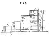
- a mechanism for moving stepped floors of such a telescopic type is disclosed, for example, in Japanese Patent Application No. 61-121000 entitled “Movable Stand” and filed by the applicant of the present patent application. The mechanism is shown in Fig. 5.
- the mechanism includes a wire (c) having a front end secured to a frontmost stepped floor (a) and a rear end secured to and wound around a drum (b).
- a wire (c) having a front end secured to a frontmost stepped floor (a) and a rear end secured to and wound around a drum (b).
- stepped floors are successively accommodated into a rearmost stepped seat (d).
- another wire (g) is taken up onto the drum (b).
- the wire (g) has a front end secured to the frontmost stepped floor (a) and a rear end secured to and wound around the drum (b) and extending past a plurality of fixed pulleys (e) and (f) mounted at rear portions of the stepped floors and at lower faces of the individually adjacent rear stepped floors, respectively.
- Each of the stepped floors is moved on a floor (i) by means of a plurality of wheels (h), and the opposite sides of a rear portion of each of the stepped floors are guided by an adjacent rear one of the stepped floors. Accordingly, there is a drawback that the stepped floors are apt to move in a zigzag direction when they are extended.
- a parallel guide apparatus for a movable stand of the telescopic type wherein a pair of right and left gears which are held in meshing engagement with racks are rotated at the same speed to move each of a plurality of stepped floors straightforwardly.
- Such an apparatus is disclosed, for example, in Japanese Utility Model Laid-Open Pub. No. 61-127255.
- an apparatus for moving a stepped floor straightforwardly with respect to another stepped floor in a movable stand wherein the former stepped floor and the latter stepped floor are associated with each other such that, when the movable stand is not used, the former stepped floor is accommodated in a telescopic manner below the latter stepped floor, but when the movable stand is to be used, the former stepped floor is pulled out of the latter stepped floor and extended forwardly into a stair-like configuration, characterized in that it comprises a pair of sprocket wheel trains mounted at locations on a pair of opposite left- and right-hand side walls adjacent a rear end of the former stepped floor and each including a follower sprocket wheel and a pair of guide sprocket wheels, a connecting shaft having the follower sprocket wheels mounted for integral rotation thereon, and a pair of chains extending substantially in parallel to each other and having one ends secured to the opposite left and right end portions of
- the former stepped floor is guided in a parallel relationship by the left and right chains when it is moved with respect to the latter stepped floor. Accordingly, during movement of the former stepped floor, it can advance or retreat straightforwardly without being oscillated leftwardly or rightwardly, which will prevent collision of the stepped floors with each other and assure smooth movement of the former stepped floor.
- the apparatus according to the present invention may be provided between each adjacent ones of the stepped floors.
- the follower sprocket wheel of each of the sprocket wheel trains is disposed below and between the guide sprocket wheels, and an associated one of the chains extends in a substantially inverted ⁇ -shape along the follower sprocket wheel and the guide sprocket wheels.
- the apparatus can thus be applied even to stepped floors which include a reinforcing beam mounted on a lower face of a central portion thereof and extending in the forward and backward direction.
- a movable stand 1 is composed of a plurality of stepped floors including a first or frontmost stepped floor 2, second and third stepped floors 3 and 4 located rearwardly of the stepped floors 2 and 3, respectively, and a fourth or rearmost stepped floor (not shown) located rearwardly of the third stepped floor 3.
- Each of the stepped floors 2, 3 and 4 is smaller in width and height than an adjacent stepped floor on the rear side thereof.
- the stepped floors 2, 3 and 4 are associated with each other such that, when the movable stand 1 is not used, the stepped floors 2, 3 and 4 are accommodated successively in a telescopic manner under the rearmost stepped floor, but when the movable stand 1 is to be used, the stepped floors 2, 3 and 4 are extended forwardly into a stair-like configuration.
- the stepped floors 2, 3 and 4 are driven to move by driving means (not shown).
- the mechanism for moving the stepped floors 2, 3 and 4 may be similar in construction to the mechanism shown in Fig. 5. Accordingly, description of the mechanism is omitted herein to avoid redundancy, and only a stepped floor moving mechanism according to the present invention will be described herein.
- the frontmost stepped floor 2 has a box-like configuration which is open at the bottom thereof and includes a base plate 2a, a pair of front and rear plates 2b and 2c extending downwardly from the opposite front and rear edges of the base plate 2a, and a pair of left- and right-hand side plates 2d extending downwardly from the opposite left- and right-hand side edges of the base plate 2a.
- the second stepped floor 3 includes a base plate 3a, and a pair of front and rear plates 3b and 3c and a pair of side plates 3d extending downwardly from the base plate 3a while the third stepped floor 4 includes a base plate 4a, and a pair of front and rear plates 4b and 4c and a pair of side plates 4d extending downwardly from the base plate 4a.
- Each of the first and second stepped floors 2 and 3 has a pair of left and right vertical mounting plates 5 provided at and extending rearwardly from upper portions of the opposite side edges of the rear plate 2c or 3c thereof.
- a pair of shafts 6 and 7 are mounted in a predetermined spaced relationship at locations near an upper edge on an inner face of each of the mounting plates 5.
- a pair of guide sprocket wheels 8 and 9 are supported for rotation on the shafts 6 and 7, respectively.
- a horizontal connecting shaft 10 is supported for rotation on and extends between a pair of bearings 10a mounted at locations between and below the front and rear guide sprocket wheels 8 and 9 on the left and right opposing mounting plates 5 of each of the stepped floors 2 and 3.
- a pair of follower sprocket wheels 11 are mounted for integral rotation at locations near the opposite left and right ends of the connecting shaft 10.
- a left-hand side roller chain 12 is shown.
- the roller chain 12 shown has a front end portion 12a secured to a lower portion at the left end of a rear face of the front plate 3b of the stepped floor 3.
- An intermediate portion 12b of the roller chain 12 extends in a substantially inverted R-shape as viewed in side elevation around and between the guide sprocket wheel 8, follower sprocket wheel 11 and guide sprocket wheel 9, and a rear end portion of the roller chain 12 is secured to a front face of the rear plate 3c of the stepped floor 3.
- a right-hand side roller chain 13 is disposed in a symmetrical relationship to the left-hand side roller chain 12 and thus has a rear end portion 13a, an intermediate portion 13b and a rear end portion disposed in a similar manner to the corresponding ones of the left-hand side roller chain 12.
- a similar mechanism is provided for the second stepped floor 3.
- a pair of sprocket wheel trains each including a pair of guide sprocket wheels 8 and 9 and a follower sprocket wheel 11 are mounted on the left and right mounting plates 5 of the second stepped floor 3, and a pair of left- and right-hand side roller chains 12 and 13 are secured at the opposite ends thereof to the third stepped floor 4 and extend in parallel to each other along the sprocket wheel trains on the second stepped floor 3.
- the follower sprocket wheels 11 are mounted for integral rotation on a connecting shaft 10.
- the stepped floors 2, 3 and 4 are positioned in a vertically overlapping relationship, and the sprocket wheel trains on the stepped floors 2, 3 and 4 are also positioned in a vertically overlapping relationship.
- the left- and right-hand side sprocket wheel trains on the stepped floor 2 are moved forwardly while stroking the roller chains 12 and 13.
- the left and right sprocket wheels 11 are rotated in an integral relationship by means of the connecting link 10, a front end portion of the stepped floor 2 is advanced straightforwardly without being oscillated in the leftward or rightward direction.
- the stepped floor 3 is pulled out and advanced straightforwardly with respect to the adjacent stepped floor 4 on the rear side.
Applications Claiming Priority (3)
| Application Number | Priority Date | Filing Date | Title |
|---|---|---|---|
| JP34528/88 | 1988-03-17 | ||
| JP3452888U JPH0427964Y2 (de) | 1988-03-17 | 1988-03-17 | |
| FR9304940A FR2704586B3 (fr) | 1988-03-17 | 1993-04-27 | Dispositif de mouvement d'un plancher à paliers d'un gradin mobile. |
Publications (2)
| Publication Number | Publication Date |
|---|---|
| EP0337592A1 true EP0337592A1 (de) | 1989-10-18 |
| EP0337592B1 EP0337592B1 (de) | 1991-07-31 |
Family
ID=26230280
Family Applications (1)
| Application Number | Title | Priority Date | Filing Date |
|---|---|---|---|
| EP89301016A Expired EP0337592B1 (de) | 1988-03-17 | 1989-02-02 | Bewegungsvorrichtung für den Stufenboden einer beweglichen Tribüne |
Country Status (2)
| Country | Link |
|---|---|
| EP (1) | EP0337592B1 (de) |
| FR (1) | FR2704586B3 (de) |
Cited By (3)
| Publication number | Priority date | Publication date | Assignee | Title |
|---|---|---|---|---|
| US6050366A (en) * | 1996-07-15 | 2000-04-18 | Hydraulic Technical Services (Consultants) Ltd. | Combined stairway and lift installation and a retractable stairway |
| CN107795156A (zh) * | 2016-12-01 | 2018-03-13 | 陕西长恨歌演艺文化有限公司 | 一种可隐藏活动看台系统及其展开和收纳方法 |
| US10584505B2 (en) * | 2017-10-23 | 2020-03-10 | Jimmy D'Joos | Rolling support for bleachers |
Citations (5)
| Publication number | Priority date | Publication date | Assignee | Title |
|---|---|---|---|---|
| US3400502A (en) * | 1966-09-22 | 1968-09-10 | American Seating Co | Telescoping platform structure |
| DE3013493A1 (de) * | 1979-04-12 | 1980-10-30 | Nijha Nv | Ausfahrbare tribuene |
| DE3013530A1 (de) * | 1979-04-12 | 1980-10-30 | Nijha Nv | Ausfahrbare tribuene |
| DE2935440A1 (de) * | 1979-09-01 | 1981-03-19 | Telekon GmbH, 5000 Köln | Antrieb fuer eine teleskoptribuene |
| FR2485602A1 (fr) * | 1980-06-30 | 1981-12-31 | Mayen Sarl | Installation de gradins mobiles |
-
1989
- 1989-02-02 EP EP89301016A patent/EP0337592B1/de not_active Expired
-
1993
- 1993-04-27 FR FR9304940A patent/FR2704586B3/fr not_active Expired - Lifetime
Patent Citations (5)
| Publication number | Priority date | Publication date | Assignee | Title |
|---|---|---|---|---|
| US3400502A (en) * | 1966-09-22 | 1968-09-10 | American Seating Co | Telescoping platform structure |
| DE3013493A1 (de) * | 1979-04-12 | 1980-10-30 | Nijha Nv | Ausfahrbare tribuene |
| DE3013530A1 (de) * | 1979-04-12 | 1980-10-30 | Nijha Nv | Ausfahrbare tribuene |
| DE2935440A1 (de) * | 1979-09-01 | 1981-03-19 | Telekon GmbH, 5000 Köln | Antrieb fuer eine teleskoptribuene |
| FR2485602A1 (fr) * | 1980-06-30 | 1981-12-31 | Mayen Sarl | Installation de gradins mobiles |
Cited By (3)
| Publication number | Priority date | Publication date | Assignee | Title |
|---|---|---|---|---|
| US6050366A (en) * | 1996-07-15 | 2000-04-18 | Hydraulic Technical Services (Consultants) Ltd. | Combined stairway and lift installation and a retractable stairway |
| CN107795156A (zh) * | 2016-12-01 | 2018-03-13 | 陕西长恨歌演艺文化有限公司 | 一种可隐藏活动看台系统及其展开和收纳方法 |
| US10584505B2 (en) * | 2017-10-23 | 2020-03-10 | Jimmy D'Joos | Rolling support for bleachers |
Also Published As
| Publication number | Publication date |
|---|---|
| EP0337592B1 (de) | 1991-07-31 |
| FR2704586A3 (fr) | 1994-11-04 |
| FR2704586B3 (fr) | 1995-03-10 |
Similar Documents
| Publication | Publication Date | Title |
|---|---|---|
| GB2260127A (en) | Computer controlled conveying and storage system | |
| US5406761A (en) | Room-space partition made of movable wall elements | |
| CN110127278B (zh) | 一种翻纸机的翻转输送结构 | |
| GB2243133A (en) | Linear motor driven passenger conveyor and treadboard therefor | |
| EP0337592B1 (de) | Bewegungsvorrichtung für den Stufenboden einer beweglichen Tribüne | |
| US2762515A (en) | Garage structures and similar storage devices | |
| GB2211492A (en) | Storage and retrieval machine for tote pans | |
| EP0958217B1 (de) | Stapelwechselvorrichtung | |
| DE2722320A1 (de) | Foerderer mit schuppen | |
| EP1333001B1 (de) | Fahrtreppe | |
| DE3545298C2 (de) | ||
| EP0430892A1 (de) | Hubstapler zum Entfernen und Einordnen von Kraftfahrzeugen in ein automatisches Parksystem | |
| DE3330620A1 (de) | Normpaletten-foerdersystem fuer laengs- und querfoerderung | |
| JPH10120115A (ja) | 自動倉庫における移動台車の移載装置 | |
| JPH0427964Y2 (de) | ||
| CN212652614U (zh) | 一种用于纵筋绑扎的位置调节机构 | |
| KR910008267B1 (ko) | 승강횡행식 주차 설비 | |
| JPH0572825U (ja) | スクリュ−駆動装置 | |
| JP3079432B2 (ja) | 水平循環式駐車設備 | |
| JPS6238273B2 (de) | ||
| JPH0978876A (ja) | 駐車設備のパレット横送り装置 | |
| JP3800543B2 (ja) | 印刷物搬送装置 | |
| JPS63167555U (de) | ||
| JPH0748895Y2 (ja) | 移動観覧席における段床係留装置 | |
| JP2565745B2 (ja) | 垂直循環式駐車装置 |
Legal Events
| Date | Code | Title | Description |
|---|---|---|---|
| PUAI | Public reference made under article 153(3) epc to a published international application that has entered the european phase |
Free format text: ORIGINAL CODE: 0009012 |
|
| AK | Designated contracting states |
Kind code of ref document: A1 Designated state(s): DE FR GB NL |
|
| 17P | Request for examination filed |
Effective date: 19900109 |
|
| 17Q | First examination report despatched |
Effective date: 19901205 |
|
| GRAA | (expected) grant |
Free format text: ORIGINAL CODE: 0009210 |
|
| AK | Designated contracting states |
Kind code of ref document: B1 Designated state(s): DE FR GB NL |
|
| REF | Corresponds to: |
Ref document number: 68900171 Country of ref document: DE Date of ref document: 19910905 |
|
| EN | Fr: translation not filed | ||
| PG25 | Lapsed in a contracting state [announced via postgrant information from national office to epo] |
Ref country code: FR Effective date: 19911227 |
|
| PLBE | No opposition filed within time limit |
Free format text: ORIGINAL CODE: 0009261 |
|
| STAA | Information on the status of an ep patent application or granted ep patent |
Free format text: STATUS: NO OPPOSITION FILED WITHIN TIME LIMIT |
|
| 26N | No opposition filed | ||
| REG | Reference to a national code |
Ref country code: FR Ref legal event code: ST |
|
| PGFP | Annual fee paid to national office [announced via postgrant information from national office to epo] |
Ref country code: GB Payment date: 19980126 Year of fee payment: 10 |
|
| PGFP | Annual fee paid to national office [announced via postgrant information from national office to epo] |
Ref country code: DE Payment date: 19980206 Year of fee payment: 10 |
|
| PGFP | Annual fee paid to national office [announced via postgrant information from national office to epo] |
Ref country code: NL Payment date: 19980226 Year of fee payment: 10 |
|
| PG25 | Lapsed in a contracting state [announced via postgrant information from national office to epo] |
Ref country code: GB Free format text: LAPSE BECAUSE OF NON-PAYMENT OF DUE FEES Effective date: 19990202 |
|
| PG25 | Lapsed in a contracting state [announced via postgrant information from national office to epo] |
Ref country code: NL Free format text: LAPSE BECAUSE OF NON-PAYMENT OF DUE FEES Effective date: 19990901 |
|
| GBPC | Gb: european patent ceased through non-payment of renewal fee |
Effective date: 19990202 |
|
| PG25 | Lapsed in a contracting state [announced via postgrant information from national office to epo] |
Ref country code: DE Free format text: LAPSE BECAUSE OF NON-PAYMENT OF DUE FEES Effective date: 19991201 |