EP0337080B1 - Verfahren zur Herstellung von Giessformen aus tongebundenem Formsand - Google Patents
Verfahren zur Herstellung von Giessformen aus tongebundenem Formsand Download PDFInfo
- Publication number
- EP0337080B1 EP0337080B1 EP89102826A EP89102826A EP0337080B1 EP 0337080 B1 EP0337080 B1 EP 0337080B1 EP 89102826 A EP89102826 A EP 89102826A EP 89102826 A EP89102826 A EP 89102826A EP 0337080 B1 EP0337080 B1 EP 0337080B1
- Authority
- EP
- European Patent Office
- Prior art keywords
- mold
- cast iron
- clay
- molding sand
- coating agent
- Prior art date
- Legal status (The legal status is an assumption and is not a legal conclusion. Google has not performed a legal analysis and makes no representation as to the accuracy of the status listed.)
- Expired - Lifetime
Links
Images
Classifications
-
- B—PERFORMING OPERATIONS; TRANSPORTING
- B22—CASTING; POWDER METALLURGY
- B22C—FOUNDRY MOULDING
- B22C1/00—Compositions of refractory mould or core materials; Grain structures thereof; Chemical or physical features in the formation or manufacture of moulds
-
- B—PERFORMING OPERATIONS; TRANSPORTING
- B22—CASTING; POWDER METALLURGY
- B22C—FOUNDRY MOULDING
- B22C3/00—Selection of compositions for coating the surfaces of moulds, cores, or patterns
Definitions
- the invention relates to a method for producing casting molds from clay-bound molding sand for gray cast iron, malleable cast iron, spheroidal cast iron and heavy metal castings.
- clay-bound molding sands contain quartz sand, clay and water, mostly also glossy carbon formers, e.g. Coal dust, to improve the casting surface and to condition the molding sand system (molding material).
- glossy carbon is formed in the heat under a reducing atmosphere, which deposits on the mold wall and reduces or prevents penetration of the liquid metal into the sand mold.
- the disadvantage of glossy carbon-containing molding sands is the formation of pyrolysis products during casting.
- An environmentally friendly molding sand system in which no gaseous, liquid or solid pollutants arise during casting, is clay-bound molding sand, which consists only of sand, in particular quartz sand, an inorganic binder such as clay (e.g. bentonite and / or kaolin) and water.
- clay-bound molding sand which consists only of sand, in particular quartz sand, an inorganic binder such as clay (e.g. bentonite and / or kaolin) and water.
- molding sands that are free of shiny carbon formers, especially for gray and malleable cast iron.
- the glossy carbon formers which are usually in the form of coal dusts or synthetic coal dusts, pitches, bitumen, synthetic resins such as polystyrene, etc., are also added to the entire molding sand system, although the desired effect has only a limited effect on the mold surface when the liquid metal is poured in.
- the coating materials contain e.g. Clays, talc, quartz, mica, zirconium silicate, magnesite, aluminum silicate and chamotte.
- coke and graphite can also be used as inorganic raw materials. These raw materials are the intended portion of the form coating; they cover the mold surface and close the sand pores against the penetration of the casting metal.
- the mold coating materials generally contain a carrier liquid, such as water or alcohol, which form a suspension with the base materials so that the mold coating material can be processed.
- the mold coatings generally also contain organic binders, such as celluloses, alginates and stearates. With the help of these substances, the suspensions are thickened and / or stabilized, whereby the settling of the solid particles is inhibited. In addition, they can contribute to the bond between the base material particles and to the adhesion to the molded part surface in the coating.
- the mold coatings contain binders such as starch derivatives, lignin derivatives, resins and plastics. In the coating, these serve to bond between the base material particles and to adhere the coating to the surface of the molded part.
- Both the suspending agents and the binders are decomposed during the casting to form pyrolysis products, so that they represent an environmental impact at the workplace and in the exhaust air.
- Mold coatings which do not contain pyrolytically decomposable organic suspending agents and / or binders are also known for special applications; however, these mold coatings have hitherto only ever been used in conjunction with molding sand systems which contain glossy carbon formers and / or pyrolytically decomposable organic constituents, so that the formation of environmentally harmful pyrolysis products could not be avoided.
- the invention has for its object to avoid the formation of environmentally harmful pyrolysis products in the production of casting molds from clay-bound molding sand, which are provided with coatings from mold coating materials.
- casting molds are obtained which are coated uniformly on the one hand with a mold coating material, while on the other hand no or only a small amount of environmentally harmful pyrolysis products are formed during the casting.
- the molding sand or the coating material is essentially free of pyrolytically decomposable organic constituents does not exclude that small amounts of organic impurities may be present.
- the mold coating materials used according to the invention can contain one or more of the following refractory inorganic constituents: clays, talc, quartz, mica, zirconium silicate, magnesite, aluminum silicate and chamotte.
- clays talc, quartz, mica, zirconium silicate, magnesite, aluminum silicate and chamotte.
- graphite or coke can be used as inorganic constituents. These raw materials do not release any environmentally harmful pyrolysis product when cast.
- Mold coatings are preferably used in which the particle size of the refractory inorganic constituents or base materials is less than about 75 ⁇ m, preferably less than about 60 ⁇ m.
- the particle size of the refractory inorganic constituents or base materials is less than about 75 ⁇ m, preferably less than about 60 ⁇ m.
- the primary particle size of bentonite and kaolin can range down to about 0.1 ⁇ m, e.g. in the case of bentonite, a maximum of the primary particles is in the range of approximately 1 ⁇ m.
- a mold coating material in the form of an aqueous dispersion having a solids content of about 300 to is preferably used 500 g / l, in particular from 450 to 500 g / l.
- a liquefying agent eg 0.5% of a combination of high polymer phosphates
- an inorganic anti-settling agent eg 7.5% of an alkaline activated bentonite; trade name TIXOTON (R)
- the base material eg graphite, kaolin etc.
- a laboratory stirrer can be used to prepare the dispersion.
- the solids content of the dispersions is generally adjusted so that a viscosity which is favorable for processing is obtained. The viscosity can be easily determined using a viscosity measuring cup.
- a DIN viscosity measuring cup that holds 100 ml and that has an outlet diameter of 4 mm can be used for this purpose (Ford cup).
- the dispersion generally has the correct consistency if the flow time in the Ford cup is 15 DIN seconds. is.
- the solids content of the dispersions is generally between about 300 and 500 g / l, preferably about 450 to 500 g / l.
- the most favorable solids concentration depends, among other things, on the type, nature and particle size of the raw materials used. For example, when using swellable clays, the solids concentration of the dispersions is at an expiry time of 15 DIN seconds. lower than the solids concentration when using quartz or graphite.
- VDG leaflet P79 "Testing of mold coating materials", March 1976 edition (published by the Association of German Foundry Experts). This leaflet includes the Determination of bulk density, loss on ignition, volatile constituents, grain size, solids content, chemical composition, viscosity, settling behavior and durability.
- the molding sand mixtures used in the examples are composed of 100 parts by weight of F32 quartz sand (a quartz sand from Frechen quartz sand with an average grain diameter of 0.23 mm), 9 parts by weight of alkaline activated foundry bentonite ( GEKO (R) ) and so much water that the bulk density as a control variable after a total mixing time of 3 minutes in the Eirich swirler R07 was 0.800 kg / l (cf. VDG leaflet P 37, edition March 1976).
- the following mixing sequence was chosen: The quartz sand was mixed with the greater part of the required water (coarse water) for 0.5 min. premixed. After adding the bentonite, 1.5 min. mixed on. The required amount of residual water (amount of fine water) was calculated from the bulk density then determined, and after its addition, 1 min. ready mixed.
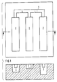
- the molding sand specified above was used to produce molds according to the 3-bar model on a Brunkel-Wagner vibratory press molding machine (APM-0).
- the lower case of this model is shown in plan view and in section in FIG. 1. It contains three bars 1, 2 and 3 of different depths, which are connected to one another by a common casting channel 4.
- the liquid metal is poured through an opening 5 in an upper box, not shown.
- the casting weight including the pouring system (channel 4 and opening 5) is 12.5 kg. With a sand weight of 30 kg per mold, this results in a ratio of metal to sand of 1: 2.4.
- the coating material dispersion was applied with the aid of a water atomizer (nozzle diameter 1.5 mm).
- the amount of coating applied was determined by weighing (difference formation from the weight after and before application, subtraction of the water content).
- a cast iron melted in a medium-frequency induction crucible furnace was cast at a casting temperature of approximately 1420 ° C.
- the castings cooled in the mold overnight and were emptied the next morning.
- the loose sand adhering to the cast grapes was removed by hammer blows. Then the adherent amount of sand, which had to be removed by steel gravel blasting, was measured by weight.
- the surface roughness of the castings was measured on the surfaces in the mold box below.
- the measurements were carried out with a roughness depth measuring device, model M4 from Microtechnik, Liederbach.
- the roughness was measured five times on each casting, and the averaged roughness (Rz) was calculated from the measured values.
- the mold box from which gaseous pollutants are emitted after pouring, was surrounded by a cuboid metal hood, which had an opening at the top for introducing the measuring lines.
- the metal hood was immediately after the Pouring over the molding box. By attaching the hood, the exhaust gases could be measured from a homogeneous, continuously changing gas atmosphere.
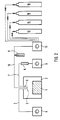
- the measuring arrangement is shown in Fig. 2.
- the cover 2 is slipped over the molding box 1, through the upper opening 3 of which three measuring lines are guided.
- the measuring line 4 leads from a CO measuring probe 5 inside the cover to the CO measuring device 6.
- the measuring line 7 leads via an adsorption tube 8 filled with silica gel for the aromatic hydrocarbons to a suction pump 9.
- the measuring line 10 leads via a bottle 11, in the water vapor is condensed to a flame ionization detector 12 (FID) with built-in suction pump.
- the flame ionization detector is calibrated using a calibration gas (C 3 H 8 ) which is removed from the calibration gas container 13. Further, the fuel gas tank 14 (N 2/0 2) and 15 (H 2) and the inert gas tank 16 (N 2) connected to the flame ionization detector.
- the following gaseous pollutants were determined:
- a flame ionization detector (model RS 5 from Ratfisch, Kunststoff) with connected X, Y recorder was used for the continuous registration of the measured values.
- the measurement curves registered under constant conditions were cut out for evaluation, and the respective areas were weighed and converted to area units.
- the areas determined were compared in relation to the zero sample (clay-bound molding sand without further addition); the maximum occurring hydrocarbon concentrations are given in absolute values.
- the measurement was carried out using an infrared gas analyzer (model EFAW 215, Bosch, Stuttgart). The CO values were measured at 1 min intervals. registered.
- the evaluation of the measured values was carried out as described under a) for the volatile hydrocarbons by determining the area units via the basis weight of the recorded individual values.
- the relative representation was based on clay-bound molding sand as standard and the maximum values were given as absolute values.
- a gas stream was passed over 10 g of granulated silica gel in the adsorption tube 8 using a membrane suction pump 9 (model 3 from Hartmann and Braun, output about 250 l / h) with a gas meter to adsorb the aromatic components.
- the silica gel granules were then eluted with diethyl ether (25 ml) and the eluate was examined by gas chromatography for benzene and phenol; Benzene and phenol were determined in separate steps.
- the gas chromatograph used (Carlo Erba) was equipped with a flame ionization detector (FID) as in the determination of the volatile hydrocarbons.
- compositions of the molding sand systems are shown in Table I, the composition of the molding sand systems and the pollutant emissions during casting are given in Table II.
- An essential feature of this process is that only a fraction of the total amount of glossy carbon former present in the sand system is required to improve the casting surface, but the greater part of the glossy carbon former is only carried along.
- it is absolutely necessary to limit the proportion of pyrolysis products to a minimum, i.e. to reduce possible sources for the formation of pyrolysis products (pyrolytically decomposable carbon-containing substances).
- the pollutant load measured in the casting test can thus be significantly reduced, the roughness depth values of known molding sand systems being reached or even being fallen below.
Landscapes
- Engineering & Computer Science (AREA)
- Mechanical Engineering (AREA)
- Chemical & Material Sciences (AREA)
- Materials Engineering (AREA)
- Mold Materials And Core Materials (AREA)
- Silicates, Zeolites, And Molecular Sieves (AREA)
- Preparation Of Clay, And Manufacture Of Mixtures Containing Clay Or Cement (AREA)
Description
- Die Erfindung betrifft ein Verfahren zur Herstellung von Gießformen aus tongebundenem Formsand für Grauguß, Temperguß, Sphäroguß und Schwermetallguß.
- Bei der Formherstellung für Gußstücke aus Stahl, Grauguß, Temperguß, Sphäroguß und Schwermetallguß hat der tongebundene Formsand nach wie vor mit etwa 95 % des gesamten Formsandbedarfs dominierende Bedeutung (vgl. z.B. R.Weiss und U. Kleinheyer, Gießerei, 74, 1987, Nr. 21, Seite 629).
- Tongebundene Formsande enthalten neben den umweltfreundlichen Bestandteilen Quarzsand, Ton und Wasser, meist noch Glanzkohlenstoffbildner, z.B. Kohlenstaub, zur Verbesserung der Gußoberfläche und zur Konditionierung des Formsandsystems (Formstoff). Beim Abguß bildet sich in der Hitze unter reduzierender Atmosphäre Glanzkohlenstoff, der sich an der Formwand abscheidet und ein Penetrieren des flüssigen Metalls in die Sandform vermindert bzw. verhindert. Der Nachteil glanzkohlenstoffhaltiger Formsande ist die Entstehung von Pyrolyseprodukten beim Abguß. Diese Schadstoffe am Arbeitsplatz, in der Abluft und den Altsanden von Gießereien sind heute nur noch in begrenztem Umfang tolerierbar und werden für viele Gießereien zunehmend zu einem Umweltproblem mit wirtschaftlichen und manchmal existenziellen Konsequenzen. Es ist deshalb ein vordringliche Aufgabe, die beim Abguß entstehenden Schadstoffe zu vermindern oder ganz zu verhindern.
- Ein umweltfreundliches Formsandsystem, bei dem keinerlei gasförmige, flüssige oder feste Schadstoffe beim Abguß entstehen, ist der tongebundene Formsand, der nur aus Sand, insbsondere Quarzsand, einem anorganischen Binder, wie Ton (z.B. Bentonit und/oder Kaolin) und Wasser besteht. Bei Verwendung eines derartigen Formsandsystems müssen allerdings Sandanhaftungen sowie eine schlechtere und rauhere Gußoberfläche in Kauf genommen werden, was in der Praxis aus Qualitätsgründen nicht möglich ist.
- Deshalb ist es bisher auch nicht möglich, insbesondere bei Grau- und Temperguß, mit Formsanden zu arbeiten, die frei von Glanzkohlenstoffbildnern sind. Die Glanzkohlenstoffbildner, die üblicherweise in Form von Kohlenstäuben oder synthetischen Kohlenstäuben, Pechen, Bitumen, Kunstharzen, wie Polystyrol usw., vorliegen, werden darüberhinaus dem gesamten Formsandsystem zugesetzt, obwohl der gewünschte Effekt nur begrenzt an der Formoberfläche beim Eingießen des flüssigen Metalls wirksam wird.
- Andererseits ist es bekannt, die Gießformen mit Formüberzugstoffen zu überziehen. Die Formüberzugstoffe haben den Zweck, die Formteiloberfläche zu beeinflussen, das Gußstückaussehen zu verbessern, das Gußstück metallurgisch zu beeinflussen und/oder Gußfehler zu vermeiden. Die Formüberzugstoffe enthalten als Grundstoffe z.B. Tone, Talkum, Quarz, Glimmer, Zirkonsilicat, Magnesit, Aluminiumsilicat und Schamotte. Im weiteren Sinn kommen als anorganische Grundstoffe auch Koks und Graphit infrage. Diese Grundstoffe sind der zweckbestimmende Anteil des Formüberzugstoffs; sie überdecken die Formoberfläche und schließen die Sandporen gegen das Eindringen des Gießmetalls.
- Weiterhin enthalten die Formüberzugstoffe im allgemeinen eine Trägerflüssigkeit, wie Wasser oder Alkohol, die mit den Grundstoffen eine Suspension bilden, damit der Formüberzugstoff verarbeitbar wird. Weiterhin enthalten die Formüberzugstoffe im allgemeinen organische Bindemittel, wie Cellulosen, Alginate und Stearate. Mit Hilfe dieser Stoffe werden die Suspensionen verdickt und/oder stabilisiert, wodurch das Absetzen der Feststoffteilchen gehemmt wird. Außerdem können sie im Überzug zur Bindung zwischen den Grundstoffteilchen und zur Haftung an der Formteiloberfläche beitragen.
- Schließlich enthalten die Formüberzugstoffe Bindemittel, wie Stärkederivate, Ligninderivate, Harze und Kunststoffe. Diese dienen im Überzug zur Bindung zwischen den Grundstoffteilchen und zur Haftung des Überzugs an der Formteiloberfläche.
- Sowohl die Suspensionsmittel als auch die Bindemittel werden beim Abguß unter Bildung von Pyrolyseprodukten zersetzt, so daß sie ein Umweltbelastung am Arbeitsplatz und in der Abluft darstellen.
- Eine zusammenfassende Darstellung der Formüberzugstoffe findet sich beispielsweise im VDG-Merkblatt R 150, August 1973, herausgegeben vom Verein Deutscher Gießereifachleute.
- Für Spezialanwendungen sind zwar auch Formüberzugstoffe bekannt, die keine pyrolytisch zersetzbaren organischen Suspensionsmittel und/oder Bindemittel enthalten; diese Formüberzugstoffe wurden jedoch bisher immer nur in Verbindung mit Formsandsystemen verwendet, die Glanzkohlenstoffbildner und/oder pyrolytisch zersetzbare organische Bestandteile enthielten, so daß die Bildung von umweltschädlichen Pyrolyseprodukten nicht zu vermeiden war.
- Der Erfindung liegt die Aufgabe zugrunde, bei der Herstellung von Gießformen aus tongebundenem Formsand, die mit Überzügen aus Formüberzugstoffen versehen werden, die Bildung von umweltschädlichen Pyrolyseprodukten zu vermeiden.
- Diese Aufgabe wird bei dem eingangs definierten Verfahren durch die Kombination folgender Schritte gelöst:
- (a) Herstellung einer Form aus einem Formsand, der im wesentlichen frei von Glanzkohlenstoffbildnern und pyrolytisch zersetzbaren organischen Bestandteilen ist, und
- (b) Aufbringung eines die üblichen feuerfesten anorganischen Bestandteile enthaltenden Formüberzugstoffs, der im wesentlichen frei von pyrolytisch zersetzbaren organischen Bestandteilen ist, zumindest auf diejenigen Oberflächen der Form, die mit dem gegossenen Metall in Berührung kommen.
- Mit Hilfe des erfindungsgemäßen Verfahrens erhält man Gießformen, die einerseits mit einem Formüberzugstoff gleichmäßig beschichtet sind, während andererseits beim Abguß keine oder nur geringe Menge an umweltschädlichen Pyrolyseprodukten entstehen.
- Die Angabe, daß der Formsand bzw. der Formüberzugstoff im wesentlichen frei von pyrolytisch zersetzbaren organischen Bestandteilen ist, schließt nicht aus, daß geringe Mengen an organischen Verunreinigungen vorhanden sein können.
- Die erfindungsgemäß verwendeten Formüberzugstoffe können einen oder mehrere der folgenden feuerfesten anorganischen Bestandteile enthalten: Tone, Talkum, Quarz, Glimmer, Zirkonsilicat, Magnesit, Aluminiumsilicat und Schamotte. Im weiteren Sinn können als anorganische Bestandteile Graphit bzw. Koks verwendet werden. Diese Grundstoffe setzen beim Abguß keine umweltschädigenden Pyrolyseprodukt frei.
- Vorzugsweise verwendet man Formüberzugstoffe, in denen die Teilchengröße der feuerfesten anorganischen Bestandteile oder Grundstoffe unter etwa 75 µm, vorzugsweise unter etwa 60 µm liegt. Nach unten ist der Teilchengröße keine Grenze gesetzt. Beispielsweise kann die Primärteilchengröße bei Bentonit und Kaolin bis herab zu etwa 0,1 µm reichen, wobei z.B. bei Bentonit ein Maximum der Primärteilchen im Bereich von etwa 1 µm liegt.
- Vorzugsweise verwendet man einen Formüberzugstoff in Form einer wäßrigen Dispersion mit einem Feststoffgehalt von etwa 300 bis 500 g/l, insbesondere von 450 bis 500 g/l.
- Das erfindungsgemäße Verfahren ist nachstehend erläutert.
- Zunächst wird in das Anmachwasser ein Verflüssigungsmittel (z.B. 0,5 % einer Kombination hochpolymerer Phosphate) eingemischt. Sodann erfolgt das Einrühren eines anorganischen Antiabsetzmittels (z.B. 7,5 % eines alkalisch aktivierten Bentonits; Handelsbezeichnung TIXOTON(R) ) und die Zugabe des Grundstoffes (z.B. Graphit, Kaolin usw.). Zur Herstellung der Dispersion kann man einen Laborrührer verwenden. Der Feststoffgehalt der Dispersionen wird im allgemeinen so eingestellt, daß eine für die Verarbeitung günstige Viskosität erhalten wird. Die Viskosität kann auf einfache Weise mit einem Viskositäts-Meßbecher bestimmt werden. Beispielsweise kann man zu diesem Zweck einen DIN-Viskositätsmeßbecher, der 100 ml faßt und der einen Auslaufdurchmesser von 4 mm hat, verwenden (Ford-Becher). Die Dispersion hat im allgemeinen die richtige Konsistenz, wenn die Auslaufzeit im Ford-Becher 15 DIN-Sek. beträgt. Bei dieser Auslaufzeit liegt der Feststoffgehalt der Dispersionen im allgemeinen zwischen etwa 300 und 500 g/l, vorzugsweise bei etwa 450 bis 500 g/l. Die günstigste Feststoffkonzentration hängt u.a. von der Art, der Beschaffenheit und der Teilchengröße der verwendeten Grundstoffe ab. Beispielsweise liegt die Feststoffkonzentration der Dispersionen bei Verwendung von quellfähigen Tonen bei einer Auslaufzeit von 15 DIN-Sek. niedriger als die Feststoffkonzentration bei Verwendung von Quarz oder Graphit.
- Die Laborprüfungen der Formüberzugstoffe können nach dem VDG-Merkblatt P79 "Prüfung von Formüberzugstoffen", Ausgabe März 1976 (herausgegeben durch den Verein Deutscher Gießereifachleute) durchgeführt werden. Dieses Merkblatt umfaßt die Bestimmung des Schüttgewichts, des Glühverlustes, der flüchtigen Bestandteile, der Korngröße, des Feststoffgehalts, der chemischen Zusammensetzung, der Viskosität, des Absetzverhaltens und der Haltbarkeit.
- Die in den Beispielen verwendeten Formsandmischunge setzen sich aus 100 Gewichtsteilen Quarzsand F32 (einem Quarzsand der Quarzwerke Frechen mit einem mittleren Korndurchmesser von 0,23 mm), 9 Gewichtsteilen alkalisch aktiviertem Gießereibentonit (GEKO(R) ) und so viel Wasser zusammen, daß das Schüttgewicht als Steuergröße nach einer Gesamtmitschzeit von 3 Min. im Eirich-Wirbler R07 0,800 kg/l betrug (vgl. VDG-Merkblatt P 37, Ausgabe März 1976). Es wurde nachstehende Mischfolge gewählt: Der Quarzsand wurde mit dem größeren Teil des erforderlichen Wassers (Grobwasser) 0,5 min. vorgemischt. Nach Zugabe des Bentonits wurde 1,5 min. weitergemischt. Aus dem dann ermittelten Schüttgewicht wurde die erforderliche Restwassermenge (Feinwassermenge) errechnet, und nach deren Zugabe wurde 1 min. fertiggemischt.
- Mit dem vorstehend angegebenen Formsand wurden auf einer Künkel-Wagner-Rüttelpreßformmaschine (APM-0) Formen nach dem 3-Riegel-Modell hergestellt. Der Unterkasten dieses Modells ist in Fig. 1 in der Draufsicht und im Schnitt dargestellt. Es enthält drei unterschiedlich tiefe Riegel 1, 2 und 3, die durch einen gemeinsamen Gußkanal 4 miteinander verbunden sind. Das flüssige Metall wird durch eine Öffnung 5 in einem nicht dargestellten Oberkasten eingegossen. Mit Hilfe dieses Modells wird eine differenzierte Oberflächenbeanspruchung erzielt, derart, daß das flüssige Metall aufgrund seines unterschiedlichen metallostatischen Druckes und des unterschiedlich hohen Wärmestaus unterschiedlich tief in den Formsand eindringt. Das Gußgewicht beträgt einschließlich Eingußsystem (Kanal 4 und Öffnung 5) 12,5 kg. Bei einem Sandgewicht von 30 kg pro Form ergibt sich daraus ein Verhältnis zwischen Metall und Sand von 1 : 2,4.
- Das Ausbringen der Formüberzugstoff-Dispersion erfolgte mit Hilfe eines Wasserzerstäubers (Düsendurchmesser 1,5 mm). Die aufgebrachte Überzugsmenge wurde durch Wiegen ermittelt (Differenzbildung aus dem Gewicht nach und vor dem Aufbringen, Subtraktion des Wassergehalts).
- Es wurde ein in einem Mittelfrequenz-Induktions-Tiegelofen erschmolzenes Gußeisen bei einer Gießtemperatur von etwa 1420°C vergossen. Die Gußstücke kühlten über Nacht in der Form ab und wurden am nächsten Morgen ausgeleert. Der an den Gußtrauben haftende lose Sand wurde durch Hammerschläge entfernt. Dann wurde die festhaftende Sandmenge, die durch Stahlkiesstrahlen entfernt werden mußte, gewichtsmäßig erfaßt.
- Die Rauhtiefen der Gußstücke wurden auf den im Formkasten unten liegenden Flächen gemessen. Die Messungen erfolgten mit einem Rauhtiefenmeßgerät, Modell M4 der Firma Microtechnik, Liederbach. An jedem Gußstück wurde die Rauhtiefe fünfmal gemessen, und aus den Meßwerten wurden die gemittelten Rauhtiefen (Rz) errechnet.
- Der Formkasten, aus dem nach dem Abgießen gasförmige Schadstoffe emittiert werden, wurde mit einer quaderförmigen Metallhaube umgeben, die an ihrer Oberseite eine Öffnung zum Einbringen der Meßleitungen aufwies. Die Metallhaube wurde unmittelbar nach dem Abgießen über den Formkasten gestülpt. Durch das Anbringen der Haube konnte die Messung der Abgase aus einer homogenen, sich kontinuierlich ändernden Gasatmosphäre erfolgen.
- Die Meßanordnung ist in Fig. 2 dargestellt. Über den Formkasten 1 ist die Abdeckhaube 2 gestülpt, durch deren obere Öffnung 3 drei Meßleitungen geführt sind. Die Meßleitung 4 führt von einer CO-Meßsonde 5 im Inneren der Abdeckhaube zum CO-Meßgerät 6. Die Meßleitung 7 führt über ein mit Kieselgel gefülltes Adsorptionsrohr 8 für die aromatischen Kohlenwasserstoffe zu einr Ansaugpumpe 9. Die Meßleitung 10 führt über eine Flasche 11, in der Wasserdampf kondensiert wird, zu einem Flammenionisationsdetektor 12 (FID) mit eingebauter Ansaugpumpe. Der Flammenionisationsdetektor wird mit Hilfe eines Eichgases (C3H8) geeicht, das dem Eichgasbehälter 13 entnommen wird. Ferner sind mit dem Flammenionisationsdetektor die Brenngasbehälter 14 (N2/02) und 15 (H2) sowie der Inertgasbehälter 16 (N2) verbunden. Im einzelnen wurden folgende gasförmige Schadstoffe bestimmt:
- Es wurde ein Flammenionisationsdetektor (Modell RS 5 der Firma Ratfisch, München) mit angeschlossenem X,Y-Schreiber zur kontinuierlichen Registrierung der Meßwerte verwendet.
- Die Messungen erfolgten unter konstanten Bedingungen:

- Die unter konstanten Bedingungen registrierten Meßkurven wurden zur Auswertung ausgeschnitten, und die jeweiligen Flächen wurden gewogen und auf Flächeneinheiten umgerechnet. Die ermittelten Flächen wurden relativ zur Nullprobe (tongebundener Formsand ohne weiteren Zusatz) ins Verhältnis gesetzt; die maximal auftretenden Kohlenwasserstoff-Konzentrationen sind in Absolutwerten angegeben.
- Die Messung erfolgte mit einem Infrarot-Gasanalysator (Modell EFAW 215, Bosch, Stuttgart). Die CO-Werte wurden in Abständen von jeweils 1 min. registriert.
-
- Gaseintrittstemperatur
- 25°C
- Meßbereich
- 0-5 % CO
- Meßzeit
- 25 min.
- Die Auswertung der Meßwerte erfolgte wie unter a) für die flüchtigen Kohlenwasserstoffe beschrieben, durch Bestimmung der Flächeneinheiten über das Flächengewicht der aufgezeichneten Einzelwerte. Auch hier erfolgte die relative Darstellung bezogen auf tongebundenen Formsand als Standard sowie die Angabe der Maximalwerte als Absolutwerte.
- Zur Bestimmung der aromatischen Kohlenwasserstoffe wurde mit einer Membran-Ansaugpumpe 9 (Modell 3 der Firma Hartmann und Braun, Leistung etwa 250 l/h) mit Gaszähler ein Gasstrom über 10 g granuliertes Kieselgel im Adsorptionsrohr 8 zur Adsorption der aromatischen Anteile geleitet. Das Kieselgel-Granulat wurde anschließend mit Diethylether eluiert (25 ml) und das Eluat wurde gaschromatographisch auf Benzol und Phenol untersucht; Benzol und Phenol wurden in getrennten Arbeitsgängen bestimmt. Der verwendete Gaschromatograph (Carlo Erba) war mit einem Flammenionisationsdetektor (FID) wie bei der Bestimmung der flüchtigen Kohlenwasserstoffe ausgerüstet.
-
- Säulenfüllung
- 5 % FFAP (Free Fatty Acid Phase = Mischung aus Polyethylenglykol und Terephthalsäure) auf weitporigem SiO2, behandelt mit Dichlordimethylsilan
(Volaspher A2 (R)) - Temperatur (Benzol)
- Inj. 150°C, Ofen 50°C
- Temperatur (Phenol)
- Inj. 275°C, Ofen 200°C
- Spülgas
- Helium 2 bar.
- Die durch Vergleich mit Standardlösungen erhaltenn Meßwerte für die aromatischen Gasanteile wurden in Gewichtsanteilen Benzol (adsorbiert an 10 g Kieselgel) angegeben; Phenol konnte in keiner der untersuchten Proben gefunden werden.
- Die Zusammensetzunge der Formsandsysteme sind in Tabelle I, die Zusammensetzung der Formsandsysteme sowie die Schadstoffemissionen beim Abguß sind in Tabelle II angegeben.

- Alle Prozentangaben (mit Ausnahme von %VB) beziehen sich auf das Gewicht. Der Glühverlust wurde nach dem VDG-Merkblatt P 33, Ausgabe Januar 1976 (herausgegeben vom Verein Deutscher Gießereifachleute) bestimmt. Die Verdichtbarkeit (% VB) wurde nach dem VDG-Merkblatt P 37, Ausgabe März 1976, bestimmt.

- Wie Tabelle I zeigt, werden mit den üblichen Formsandsystemen, denen als Glanzkohlenstoffbildner pyrolytisch zersetzbare kohlenstoffhaltige Substanzen, wie z.B. Kohlenstaub und Naturasphalte zugegeben wurden (System Nr. 2), gute Gußergebnisse mit glatten Oberflächen der Gußstücke erzielt.
- Ein wesentliches Merkmale dieses Verfahrens besteht darin, daß zur Verbesserung der Gußstückoberfläche nur ein Bruchteil der gesamten Menge an Glanzkohlenstoffbildner, die im Sandsystem vorhanden ist, benötigt wird, der größere Teil des Glanzkohlenstoffbildners jedoch nur mitgeschleppt wird. Zur Einhaltung bestehender Vorschriften zur Luftreinhaltung ist es aber unbedingt erforderlich, den Anteil an Pyrolyseprodukten auf ein Mindestmaß zu begrenzen, d.h. mögliche Quellen für die Entstehung von Pyrolyseprodukten (pyrolytisch zersetzbare kohlenstoffhaltige Substanzen) zu senken.
- Durch den vollständigen Verzicht auf die Verwendung von pyrolytisch zersetzbaren kohlenstoffhaltigen Verbindunge, d.h. durch Einsatz von anorganischen Formüberzugstoffen (wozu erfindungsgemäß auch Graphit und Koksmehl gehören) in wäßrigen Systemen, kann die Bildung von Schadstoffen vermieden werden. Diese Systeme sind in Tabellen I und II unter Nr. 5 bis 10 aufgeführt. Diese Systeme zeigen auch gute Gußoberflächen (geringe Rauhtiefe). Die Formsande ohne Formüberzugstoffe und ohne Glanzkohlenstoffbildner (Systeme Nr. 1 und 4) zeigen verhältnismäßig große Rauhtiefen. Die handelsüblichen Formüberzugstoffe (Systeme 11 und 12) zeigen zwar verhältnismäßig geringe Rauhtiefen, jedoch verhältnismäßig hohe Emissionen an flüchtigen Kohlenwasserstoffen.
- Mit Hilfe des erfindungsgemäßen Verfahrens kann also die im Gießversuch gemessene Schadstoffbelastung deutlich verringert weden, wobei die Rauhtiefewerte von bekannte Formsandsystemen erreicht bzw. sogar unterschritten werden.
Claims (4)
- Verfahren zur Herstellung von Gießformen aus tongebundenem Formsand für Grauguß, Temperguß, Sphäroguß und Schwermetallguß, gekennzeichnet durch die Kombination folgender Schritte:(a) Herstellung einer Form aus einem Formsand, der im wesentlichen frei von Glanzkohlenstoffbildnern und pyrolytisch zersetzbaren organischen Bestandteilen ist, und(b) Aufbringung eines die üblichen feuerfesten anorganischen Bestandteile enthaltenden Formüberzugstoffs, der im wesentlichen frei von pyrolytisch zersetzbaren organischen Bestandteilen ist, zumindest auf diejenigen Oberflächen der Form, die mit dem gegossenen Metall in Berührung kommen.
- Verfahren nach Anspruch 1, dadurch gekennzeichnet, daß man einen Formüberzugstoff mit einem oder mehreren der folgenden feuerfesten anorganischen Bestandteile verwendet: Tone, Talkum, Quarz, Glimmer, Zirkonsilicat, Magnesit, Aluminiumsilicat, Schamotte, Graphit bzw. Koks.
- Verfahren nach Anspruch 1 oder 2, dadurch gekennzeichnet, daß man einen Formüberzugstoff verwendet, in welcher die Teilchengröße der feuerfesten anorganischen Bestandteile unter etwa 75 µm, vorzugsweise unter etwa 60 µm, liegt.
- Verfahren nach einem der Ansprüche 1 bis 3, dadurch gekennzeichnet, daß man einen Formüberzugstoff in Form einer wäßrigen Dispersion mit einm Feststoffgehalt von etwa 300 bis 500 g/l, vorzugsweise von 450 bis 500 g/l verwendet.
Priority Applications (1)
| Application Number | Priority Date | Filing Date | Title |
|---|---|---|---|
| AT89102826T ATE81041T1 (de) | 1988-04-15 | 1989-02-18 | Verfahren zur herstellung von giessformen aus tongebundenem formsand. |
Applications Claiming Priority (2)
| Application Number | Priority Date | Filing Date | Title |
|---|---|---|---|
| DE3812634A DE3812634A1 (de) | 1988-04-15 | 1988-04-15 | Verfahren zur herstellung von giessformen aus tongebundenem formsand |
| DE3812634 | 1988-04-15 |
Publications (3)
| Publication Number | Publication Date |
|---|---|
| EP0337080A2 EP0337080A2 (de) | 1989-10-18 |
| EP0337080A3 EP0337080A3 (en) | 1990-10-17 |
| EP0337080B1 true EP0337080B1 (de) | 1992-09-30 |
Family
ID=6352094
Family Applications (1)
| Application Number | Title | Priority Date | Filing Date |
|---|---|---|---|
| EP89102826A Expired - Lifetime EP0337080B1 (de) | 1988-04-15 | 1989-02-18 | Verfahren zur Herstellung von Giessformen aus tongebundenem Formsand |
Country Status (5)
| Country | Link |
|---|---|
| EP (1) | EP0337080B1 (de) |
| JP (1) | JPH01306040A (de) |
| KR (1) | KR890015799A (de) |
| AT (1) | ATE81041T1 (de) |
| DE (2) | DE3812634A1 (de) |
Families Citing this family (5)
| Publication number | Priority date | Publication date | Assignee | Title |
|---|---|---|---|---|
| DE4331697A1 (de) * | 1993-09-17 | 1995-03-23 | Sued Chemie Ag | Bindemittel für Gießereiformsand |
| DE19906770C2 (de) * | 1998-08-31 | 2003-03-27 | Huettenes Albertus | Verfahren zum Herstellen eines Gußstücks |
| KR100640223B1 (ko) * | 2006-04-04 | 2006-11-01 | 임인호 | 고인쇄 금속활자 주조용 주형조성물 |
| DE602006014422D1 (de) * | 2006-11-24 | 2010-07-01 | Sintercast Ab | Neue Vorrichtung zur thermischen Analyse |
| DE102009041677A1 (de) | 2009-09-16 | 2011-03-24 | Süd-Chemie AG | Gießereiadditiv auf Grafitbasis |
Family Cites Families (4)
| Publication number | Priority date | Publication date | Assignee | Title |
|---|---|---|---|---|
| DE1433944A1 (de) * | 1964-07-18 | 1969-01-02 | Chemoil Corp | Bindemittelmischung fuer Giessereiformsand |
| NL7609076A (nl) * | 1976-08-16 | 1978-02-20 | Hoogovens Ijmuiden Bv | Vuurvast vulmateriaal. |
| DE3519367A1 (de) * | 1985-05-30 | 1986-12-04 | Giulini Chemie Gmbh, 6700 Ludwigshafen | Verfahren zur herstellung von formen, modellen und werkzeugen auf hartgips - und/oder zementbasis |
| DE3704726C3 (de) * | 1987-02-14 | 1998-01-08 | Iko Gmbh & Co Kg | Verfahren zum Beschleunigen der Wasseradsorption von als Zuschlagstoff für Gießereiformsande verwendetem Bentonit |
-
1988
- 1988-04-15 DE DE3812634A patent/DE3812634A1/de not_active Withdrawn
-
1989
- 1989-01-31 KR KR1019890001057A patent/KR890015799A/ko not_active Withdrawn
- 1989-02-18 EP EP89102826A patent/EP0337080B1/de not_active Expired - Lifetime
- 1989-02-18 DE DE8989102826T patent/DE58902349D1/de not_active Expired - Lifetime
- 1989-02-18 AT AT89102826T patent/ATE81041T1/de not_active IP Right Cessation
- 1989-04-14 JP JP1093276A patent/JPH01306040A/ja active Pending
Non-Patent Citations (1)
| Title |
|---|
| GIESSEREI 74, Nr. 21, 12.10.1987, Seiten 629-633, Düsseldorf, DE; R. Weiss et al.: "Aktuelle Anwendungstrends der Form- und Kernherstellverfahren" * |
Also Published As
| Publication number | Publication date |
|---|---|
| JPH01306040A (ja) | 1989-12-11 |
| ATE81041T1 (de) | 1992-10-15 |
| DE3812634A1 (de) | 1989-10-26 |
| KR890015799A (ko) | 1989-11-25 |
| EP0337080A2 (de) | 1989-10-18 |
| DE58902349D1 (de) | 1992-11-05 |
| EP0337080A3 (en) | 1990-10-17 |
Similar Documents
| Publication | Publication Date | Title |
|---|---|---|
| EP1095719B1 (de) | Bindemittelsystem, Kernsandgemisch und Verfahren zu seiner Herstellung | |
| DE2205437A1 (de) | ||
| WO1994026440A1 (de) | Schlichte zur herstellung von formüberzügen | |
| DE102007027577A1 (de) | Formstoffmischung, Formling für Gießereizwecke und Verfahren zur Herstellung eines Formlings | |
| EP3829798A1 (de) | Schlichtezusammensetzung zur reduzierung von formaldehyd-emissionen | |
| DE1947904A1 (de) | Feuerfestes waermeisolierendes Material | |
| US4154894A (en) | Process for treating olivine foundry sand | |
| EP1934001B8 (de) | Borsilikatglashaltige formstoffmischungen | |
| EP0337080B1 (de) | Verfahren zur Herstellung von Giessformen aus tongebundenem Formsand | |
| EP2193858A1 (de) | Gießereikerne mit verbesserten Entkernungseigenschaften II | |
| EP0111616B2 (de) | Verwendung von Zusätzen für umweltfreundliche Giessereiformsande | |
| DE2415731C2 (de) | Grünsandformmasse mit Glanzkohlenstoffbildern | |
| DE102007008104A1 (de) | Verfahren zur Regeneration von Gießereisanden | |
| EP0065034A1 (de) | Verfahren zum Auskleiden von ein Dauerfutter aufweisenden Aggregaten | |
| EP1228128A1 (de) | Aluminium- und borhaltiges bindemittelsystem auf resolbasis | |
| CH641264A5 (de) | Maschinen- apparate- und instrumententeile aus einem gemenge von sand, kies und/oder schotter. | |
| US3763080A (en) | Pressure molded articles and moldable composition | |
| DE69512426T2 (de) | Formen und kerne aus gebrochenem und gradiertem magnetiterz und verfahren zum giessen von metall unter deren verwendung | |
| WO1998045068A1 (de) | Additive für giessereisande | |
| DE2708265C3 (de) | Verfahren zur Herstellung einer selbsthärtenden und wasserlöslichen Form | |
| WO1999048634A1 (de) | Verwendung von eisenglimmer bei der herstellung von gussformen | |
| DE19906770C2 (de) | Verfahren zum Herstellen eines Gußstücks | |
| DE69703966T2 (de) | Verfahren zur Herstellung feuerfester Körper | |
| CH642876A5 (en) | Coating for moulds and cores | |
| EP0078408B1 (de) | Verfahren zur Herstellung von Giessformen für Metallguss |
Legal Events
| Date | Code | Title | Description |
|---|---|---|---|
| PUAI | Public reference made under article 153(3) epc to a published international application that has entered the european phase |
Free format text: ORIGINAL CODE: 0009012 |
|
| AK | Designated contracting states |
Kind code of ref document: A2 Designated state(s): AT BE CH DE FR IT LI SE |
|
| PUAL | Search report despatched |
Free format text: ORIGINAL CODE: 0009013 |
|
| AK | Designated contracting states |
Kind code of ref document: A3 Designated state(s): AT BE CH DE FR IT LI SE |
|
| 17P | Request for examination filed |
Effective date: 19901201 |
|
| 17Q | First examination report despatched |
Effective date: 19911212 |
|
| GRAA | (expected) grant |
Free format text: ORIGINAL CODE: 0009210 |
|
| AK | Designated contracting states |
Kind code of ref document: B1 Designated state(s): AT BE CH DE FR IT LI SE |
|
| PG25 | Lapsed in a contracting state [announced via postgrant information from national office to epo] |
Ref country code: IT Free format text: LAPSE BECAUSE OF FAILURE TO SUBMIT A TRANSLATION OF THE DESCRIPTION OR TO PAY THE FEE WITHIN THE PRESCRIBED TIME-LIMIT;WARNING: LAPSES OF ITALIAN PATENTS WITH EFFECTIVE DATE BEFORE 2007 MAY HAVE OCCURRED AT ANY TIME BEFORE 2007. THE CORRECT EFFECTIVE DATE MAY BE DIFFERENT FROM THE ONE RECORDED. Effective date: 19920930 Ref country code: SE Effective date: 19920930 Ref country code: BE Effective date: 19920930 |
|
| REF | Corresponds to: |
Ref document number: 81041 Country of ref document: AT Date of ref document: 19921015 Kind code of ref document: T |
|
| REF | Corresponds to: |
Ref document number: 58902349 Country of ref document: DE Date of ref document: 19921105 |
|
| PGFP | Annual fee paid to national office [announced via postgrant information from national office to epo] |
Ref country code: AT Payment date: 19930107 Year of fee payment: 5 |
|
| EN | Fr: translation not filed | ||
| PG25 | Lapsed in a contracting state [announced via postgrant information from national office to epo] |
Ref country code: FR Effective date: 19930219 |
|
| PGFP | Annual fee paid to national office [announced via postgrant information from national office to epo] |
Ref country code: CH Payment date: 19930224 Year of fee payment: 5 |
|
| PLBE | No opposition filed within time limit |
Free format text: ORIGINAL CODE: 0009261 |
|
| STAA | Information on the status of an ep patent application or granted ep patent |
Free format text: STATUS: NO OPPOSITION FILED WITHIN TIME LIMIT |
|
| 26N | No opposition filed | ||
| REG | Reference to a national code |
Ref country code: FR Ref legal event code: ST |
|
| PG25 | Lapsed in a contracting state [announced via postgrant information from national office to epo] |
Ref country code: AT Effective date: 19940218 |
|
| PG25 | Lapsed in a contracting state [announced via postgrant information from national office to epo] |
Ref country code: LI Effective date: 19940228 Ref country code: CH Effective date: 19940228 |
|
| REG | Reference to a national code |
Ref country code: CH Ref legal event code: PL |
|
| PGFP | Annual fee paid to national office [announced via postgrant information from national office to epo] |
Ref country code: DE Payment date: 19960102 Year of fee payment: 8 |
|
| PG25 | Lapsed in a contracting state [announced via postgrant information from national office to epo] |
Ref country code: DE Effective date: 19970618 |