EP0336340A2 - Méthode et appareil de contrôle du papillon dans un moteur à combustion interne - Google Patents
Méthode et appareil de contrôle du papillon dans un moteur à combustion interne Download PDFInfo
- Publication number
- EP0336340A2 EP0336340A2 EP89105815A EP89105815A EP0336340A2 EP 0336340 A2 EP0336340 A2 EP 0336340A2 EP 89105815 A EP89105815 A EP 89105815A EP 89105815 A EP89105815 A EP 89105815A EP 0336340 A2 EP0336340 A2 EP 0336340A2
- Authority
- EP
- European Patent Office
- Prior art keywords
- throttle valve
- motor
- value
- angular position
- return spring
- Prior art date
- Legal status (The legal status is an assumption and is not a legal conclusion. Google has not performed a legal analysis and makes no representation as to the accuracy of the status listed.)
- Granted
Links
Images


Classifications
-
- F—MECHANICAL ENGINEERING; LIGHTING; HEATING; WEAPONS; BLASTING
- F02—COMBUSTION ENGINES; HOT-GAS OR COMBUSTION-PRODUCT ENGINE PLANTS
- F02D—CONTROLLING COMBUSTION ENGINES
- F02D11/00—Arrangements for, or adaptations to, non-automatic engine control initiation means, e.g. operator initiated
- F02D11/06—Arrangements for, or adaptations to, non-automatic engine control initiation means, e.g. operator initiated characterised by non-mechanical control linkages, e.g. fluid control linkages or by control linkages with power drive or assistance
- F02D11/10—Arrangements for, or adaptations to, non-automatic engine control initiation means, e.g. operator initiated characterised by non-mechanical control linkages, e.g. fluid control linkages or by control linkages with power drive or assistance of the electric type
-
- F—MECHANICAL ENGINEERING; LIGHTING; HEATING; WEAPONS; BLASTING
- F02—COMBUSTION ENGINES; HOT-GAS OR COMBUSTION-PRODUCT ENGINE PLANTS
- F02D—CONTROLLING COMBUSTION ENGINES
- F02D41/00—Electrical control of supply of combustible mixture or its constituents
- F02D41/20—Output circuits, e.g. for controlling currents in command coils
-
- F—MECHANICAL ENGINEERING; LIGHTING; HEATING; WEAPONS; BLASTING
- F02—COMBUSTION ENGINES; HOT-GAS OR COMBUSTION-PRODUCT ENGINE PLANTS
- F02D—CONTROLLING COMBUSTION ENGINES
- F02D11/00—Arrangements for, or adaptations to, non-automatic engine control initiation means, e.g. operator initiated
- F02D11/06—Arrangements for, or adaptations to, non-automatic engine control initiation means, e.g. operator initiated characterised by non-mechanical control linkages, e.g. fluid control linkages or by control linkages with power drive or assistance
- F02D11/10—Arrangements for, or adaptations to, non-automatic engine control initiation means, e.g. operator initiated characterised by non-mechanical control linkages, e.g. fluid control linkages or by control linkages with power drive or assistance of the electric type
- F02D2011/101—Arrangements for, or adaptations to, non-automatic engine control initiation means, e.g. operator initiated characterised by non-mechanical control linkages, e.g. fluid control linkages or by control linkages with power drive or assistance of the electric type characterised by the means for actuating the throttles
- F02D2011/102—Arrangements for, or adaptations to, non-automatic engine control initiation means, e.g. operator initiated characterised by non-mechanical control linkages, e.g. fluid control linkages or by control linkages with power drive or assistance of the electric type characterised by the means for actuating the throttles at least one throttle being moved only by an electric actuator
-
- F—MECHANICAL ENGINEERING; LIGHTING; HEATING; WEAPONS; BLASTING
- F02—COMBUSTION ENGINES; HOT-GAS OR COMBUSTION-PRODUCT ENGINE PLANTS
- F02D—CONTROLLING COMBUSTION ENGINES
- F02D41/00—Electrical control of supply of combustible mixture or its constituents
- F02D41/20—Output circuits, e.g. for controlling currents in command coils
- F02D2041/202—Output circuits, e.g. for controlling currents in command coils characterised by the control of the circuit
- F02D2041/2058—Output circuits, e.g. for controlling currents in command coils characterised by the control of the circuit using information of the actual current value
Definitions
- This invention relates to a method and apparatus for controlling a throttle valve in an internal combustion engine so that the throttle valve driven by an electric motor can be opened and closed through an angle corresponding to the amount of depression of an accelerator pedal in a vehicle.
- a stepping motor is used to drive the throttle valve.
- a stepping motor for automatically controlling the open-close movement of the throttle valve is preferable in that the angular position of rotation of the throttle valve can be controlled with high accuracy, there is an inevitable tendency that the operation of the throttle valve is insufficient in its high-speed response capability.
- a D.C. motor is preferably used in lieu of the stepping motor so as to ensure the desired high-speed response capability of the throttle valve.
- attainment of the desired high-speed response capability of the throttle valve driven by the D.C. motor tends to be affected by the factors of fluctuation which include: (a) changes in the coefficient of friction of the rotor shaft of the motor; (b) non-uniform spring constants of springs of throttle valves due to non-uniformity of the characteristics of manufactured products; and (c) secular variations (so-called permanent set) of the spring constant.
- the above object of the present invention can be attained by always studying the factors of fluctuation affecting the operational characteristic of the D.C. motor.
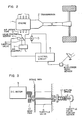
- Fig. 2 shows schematically an internal combustion engine 1 provided with an embodiment of the throttle valve control apparatus according to the present invention and shows also a drive system of a vehicle on which the engine 1 is mounted.
- the output power of the engine 1 is transmitted to wheels through a transmission 2.
- An air cleaner 7 is mounted at the inlet of an air intake pipe 9 of the engine 1, and butterfly type throttle valve 8 is disposed in the air intake pipe 9.
- the throttle valve 8 is driven for open-close movement by a D.C. motor 3 as described later with reference to Fig. 3.
- the opening of the throttle valve 8 is detected by a valve position sensor (an angular position of rotation sensor) 4 whose detection output signal is applied to a control circuit 5.
- the control circuit 5 controls current supplied to the motor 3 so that the output signal of the valve position sensor 4 coincides with an output signal of an accelerator pedal sensor 6 which detects the amount of depression of an accelerator pedal. That is, the output signal of the accelerator pedal sensor 6 is used as a target value, and the control circuit 5 controls the current supplied to the motor 3 so that the output signal of the valve position sensor 4 can follow up the target value.
- Fig. 3 shows schematically the relation between the D.C. motor 3, the throttle valve 8 disposed in a venturi V of the air intake pipe 9, and the valve position sensor 4.
- a return spring 12 is imparted with an initial load so as to normally urge the butterfly type throttle valve 8 in a direction in which the throttle valve 8 is full closed.
- the throttle valve 8 is placed in its most stable state when the movement of the throttle valve 8 urged by the force of the return spring 12 is stopped by being engaged by a stopper (not shown).
- the D.C. motor 3 rotates the throttle valve 8 through a gear pair 10 against the biasing force of the return spring 12.
- T m Torque produced by motor
- T fm Frictional torque of motor shaft
- I m Inertia of motor
- ⁇ m Rotation angle of motor
- G Gear ratio
- I g Inertia of gear pair
- K s Spring constant
- T f Frictional torque of throttle valve shaft
- T v Air resistance of throttle valve
- I Motor drive current
- K m Current/torque proportional constant of motor
- control system When, in order to provide a desired response capability, feedback of state given by is made, the control system is represented by a block diagram as shown in Fig. 1.
- the controlled blocks are surrounded by broken lines, and a balance of forced imparted to the throttle valve 8 is taken into consideration.
- the remaining blocks of the system are processed in the control circuit 5 shown in Fig. 2.
- the dashed symbol K m ′ in Fig. 1 represents the actual current/torque constant of the D.C. motor 3 and differs from the motor current/torque constant K m used as one of the parameters in the arithmetic and logical processing in the control circuit 5 shown in Fig. 2.
- Fig. 4 is a graph in which the horizontal axis represents time, and the vertical axis represents both the actual angular position of rotation of the throttle valve 8 and the actual current value supplied to the D.C. motor 3.
- the maximum value of the current that can be supplied to the D.C. motor 3 is restricted so that an excessively large current may not be supplied at the moment of starting the current supply to the D.C. motor 3.
- the response capability of the control system coincides with the transfer function given by the equation (6) after a period of time of about 0.08 sec on the time axis, because the above restriction is released from that time.
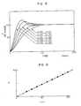
- Fig. 5 is a graph showing the response characteristic of the throttle valve 8 when the value of the parameter b is changed while maintaining the parameter a at a fixed value of 50. It will be seen in Fig. 5 that the parameter b has a value with which the possibility of appearance of an overshoot can be eliminated, and the stabilizing period can be decreased to a minimum.
- Fig. 6 is a graph in which the optimum value of the parameter b relative to a value of the parameter a and the optimum value of the parameter a relative to a value of the parameter b are plotted. It is preferable to determine the values of these parameters a and b on the basis of the graph shown in Fig. 6.
- Fig. 7 is a block diagram corresponding to Fig. 1, and, in the block diagram shown in Fig. 7, the combination of the frictional torque and the hysteresis of the return spring 12 is represented by a symbol T f ′ which is a function of ⁇ , that is, a function of the speed, and the initial position of the throttle valve 8 set by the return spring 12 is represented by a symbol ⁇ o ′.
- the initial load setting K s ′ x ⁇ o ′ of the return spring 12 is compensated in the form of in the control apparatus.
- the parameter T f ′ representing the combination of the frictional torque and the hysteresis of the return spring 12 is compensated in the form of in the control apparatus.
- the parameter T f ′ is the function of the differentiated value ⁇ . That is, the value of T f ′ changes with the speed.
- a force tending to obstruct the movement of the throttle valve 8 in the direction is produced to provide a frictional load given by (T f ′ - T f ).
- Fig. 8 is a graph showing very slight movement of the throttle valve 8 when the current supplied to the D.C. motor 3 is gradually increased and then decreased. In this case, no position control is effected, and the current supplied to the D.C. motor 3 is merely primarily considered and changed.
- Fig. 8 shows that, with the increase in the current supplied to the D.C. motor 3, the throttle valve 8 starts to move at time t1 corresponding to a current value i1, and, with the subsequent decrease in the current, the throttle valve 8 starts to move again at time t2 corresponding to a current value i2.
- Fig. 9 is a graph showing an example of the response characteristics of the embodiment shown in Fig. 7 when the relation between the parameters T f ′ and T f is given by T f ′ - T f > 0.
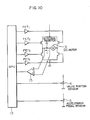
- Fig. 10 shows the internal structure of the control circuit 5 shown in Fig. 2.
- a one-chip microprocessor (MPU) 13 is an essential part of the control circuit 5 and has a program-storing ROM, a RAM and an A/D converter built therein.
- the output signal of the accelerator pedal sensor 6 and that of the throttle valve position sensor 4 are A/D converted by the A/D converter (not shown) to selectively drive four field-effect transistors FET1 to FET4 thereby controlling the current supplied to the D.C. motor 3.
- the value of the motor current of the D.C. motor 3 is detected in the form of a voltage appearing across a detection resistor 14, and, after being amplified by an amplifier 15, the detected voltage is applied to the MPU 13 so as to continuously control the value of the motor current.
- Fig. 11 is a flow chart of a sequence of arithmetic and logical processing and decision steps executed according to a control program stored in the MPU 13. The flow shown in Fig. 11 is run at an interval of a predetermined period of time under control of a time scheduler.
- step 24 the result of decision made in a step 27 as to whether or not the target value ⁇ t is approximately equal to the value of the actual position ⁇ of the throttle valve 8 is "No"
- step 27 is followed by the step 24.
- the flag is referenced in a step 29.
- step 28 is followed by a step 39 in which the flag is cleared, and the studied value of ⁇ o is determined in a step 40.
- ⁇ o is given by This studied value of ⁇ o is used in the later control.
- the current/torque constant of the D.C. motor in the steady state can be studied so that a steady-state error can be easily cancelled. Therefore, the control system can automatically adapt itself to changes in the environmental conditions and secular variations in the state mounted on the vehicle, so that the throttle valve can be highly accurately positioned without sacrificing the high-speed response capability.
- the control method described above can be easily and effectively practised so as to fully exhibit the advantages enumerated above.
Landscapes
- Engineering & Computer Science (AREA)
- Chemical & Material Sciences (AREA)
- Combustion & Propulsion (AREA)
- Mechanical Engineering (AREA)
- General Engineering & Computer Science (AREA)
- Electrical Control Of Air Or Fuel Supplied To Internal-Combustion Engine (AREA)
- Control Of Throttle Valves Provided In The Intake System Or In The Exhaust System (AREA)
Applications Claiming Priority (2)
| Application Number | Priority Date | Filing Date | Title |
|---|---|---|---|
| JP63078197A JP2513776B2 (ja) | 1988-04-01 | 1988-04-01 | スロットル弁制御方法及びその装置 |
| JP78197/88 | 1988-04-01 |
Publications (3)
| Publication Number | Publication Date |
|---|---|
| EP0336340A2 true EP0336340A2 (fr) | 1989-10-11 |
| EP0336340A3 EP0336340A3 (en) | 1990-07-04 |
| EP0336340B1 EP0336340B1 (fr) | 1995-09-27 |
Family
ID=13655286
Family Applications (1)
| Application Number | Title | Priority Date | Filing Date |
|---|---|---|---|
| EP89105815A Expired - Lifetime EP0336340B1 (fr) | 1988-04-01 | 1989-04-03 | Méthode et appareil de contrôle du papillon dans un moteur à combustion interne |
Country Status (5)
| Country | Link |
|---|---|
| US (1) | US4911125A (fr) |
| EP (1) | EP0336340B1 (fr) |
| JP (1) | JP2513776B2 (fr) |
| KR (1) | KR0137942B1 (fr) |
| DE (1) | DE68924364T2 (fr) |
Cited By (4)
| Publication number | Priority date | Publication date | Assignee | Title |
|---|---|---|---|---|
| EP0495295A2 (fr) * | 1991-01-12 | 1992-07-22 | Rover Group Limited | Système de commande de papillon pour moteur à combustion dans un véhicule |
| EP1371830A1 (fr) * | 2000-11-10 | 2003-12-17 | Mikuni Corporation | Corps de papillon a commande electronique |
| US7051615B2 (en) * | 2000-10-10 | 2006-05-30 | Mikuni Corporation | Accelerator pedal device |
| CN100439689C (zh) * | 2005-05-18 | 2008-12-03 | 株式会社日立制作所 | 转角检测装置及其方法 |
Families Citing this family (16)
| Publication number | Priority date | Publication date | Assignee | Title |
|---|---|---|---|---|
| ZA928107B (en) * | 1991-10-23 | 1993-05-07 | Transcom Gas Tech | Boost pressure control. |
| US5445125A (en) * | 1994-03-16 | 1995-08-29 | General Motors Corporation | Electronic throttle control interface |
| CN1096551C (zh) * | 1995-08-04 | 2002-12-18 | 皇家菲利浦电子有限公司 | 带有精密级联控制单元的电拖动装置 |
| JP3155694B2 (ja) * | 1995-11-09 | 2001-04-16 | 株式会社日立製作所 | スロットルバルブの制御装置及び方法 |
| JPH1113518A (ja) * | 1997-06-27 | 1999-01-19 | Aisin Seiki Co Ltd | スロットルバルブ制御装置 |
| DE19739827B4 (de) * | 1997-09-11 | 2007-05-10 | Robert Bosch Gmbh | Verfahren und Vorrichtung zur Steuerung einer Betriebsgröße eines Kraftfahrzeugs |
| US5996553A (en) * | 1998-02-17 | 1999-12-07 | General Motors Corporation | Idle actuator speed control |
| JP3511577B2 (ja) * | 1998-10-06 | 2004-03-29 | 株式会社日立製作所 | 内燃機関のスロットル装置 |
| US6318337B1 (en) * | 2000-05-19 | 2001-11-20 | Visteon Global Technologies, Inc. | Electronic throttle control |
| US6516932B2 (en) * | 2000-09-29 | 2003-02-11 | New Holland North America, Inc. | Electro-hydraulic clutch hysteresis compensation |
| US6442472B1 (en) | 2001-02-28 | 2002-08-27 | General Motors Corporation | Modification of pedal progression with acceleration feedback using electronic throttle control |
| US6523522B1 (en) | 2001-08-22 | 2003-02-25 | General Motors Corporation | Method and apparatus for operating a throttle plate motor driving a throttle plate having opposing return springs |
| EP1860518A3 (fr) * | 2005-01-18 | 2010-09-08 | Teleflex Incorporated | Assemblage de pédale et procédé |
| JP4373958B2 (ja) * | 2005-04-25 | 2009-11-25 | ジーイー・メディカル・システムズ・グローバル・テクノロジー・カンパニー・エルエルシー | 撮影装置,被検体移動装置および走査ガントリ装置 |
| KR101164252B1 (ko) | 2006-01-02 | 2012-07-09 | 주식회사 현대오토넷 | 리턴 스프링 및 감속 기어를 사용하는 모터의 제어 장치 및방법 |
| JP2011069336A (ja) * | 2009-09-28 | 2011-04-07 | Keihin Corp | 内燃機関の制御装置 |
Citations (4)
| Publication number | Priority date | Publication date | Assignee | Title |
|---|---|---|---|---|
| JPS5827840A (ja) * | 1981-08-10 | 1983-02-18 | Mitsubishi Electric Corp | 内燃機関用電子式空燃比制御装置 |
| JPS6361748A (ja) * | 1987-04-14 | 1988-03-17 | Nippon Denso Co Ltd | スロツトル弁の電気制御装置 |
| JPS6432035A (en) * | 1987-07-27 | 1989-02-02 | Mazda Motor | Throttle valve controller for engine |
| JPS6467456A (en) * | 1987-09-05 | 1989-03-14 | Nippon Air Brake Co | Brake pressure controller |
Family Cites Families (7)
| Publication number | Priority date | Publication date | Assignee | Title |
|---|---|---|---|---|
| DE2852211C2 (de) * | 1978-12-02 | 1986-01-02 | Vdo Adolf Schindling Ag, 6000 Frankfurt | Einrichtung zum Steuern der Fahrgeschwindigkeit eines Kraftfahrzeuges |
| DE3146652C1 (de) * | 1981-11-25 | 1983-06-01 | Pierburg Gmbh & Co Kg, 4040 Neuss | Einrichtung zur Stellung einer Klappe |
| JPH0621584B2 (ja) * | 1982-07-09 | 1994-03-23 | マツダ株式会社 | エンジンのスロツトル弁制御装置 |
| JPS60190626A (ja) * | 1984-03-09 | 1985-09-28 | Hitachi Ltd | 絞弁制御装置 |
| JPS61129432A (ja) * | 1984-11-27 | 1986-06-17 | Toyota Motor Corp | 車両の加速スリツプ制御装置 |
| JPH0663460B2 (ja) * | 1986-06-02 | 1994-08-22 | 株式会社日立製作所 | 電動機駆動型絞弁用の絞弁組立体 |
| US4781162A (en) * | 1986-08-04 | 1988-11-01 | Honda Giken Kogyo Kabushiki Kaisha | Throttle valve control system for an internal combustion engine |
-
1988
- 1988-04-01 JP JP63078197A patent/JP2513776B2/ja not_active Expired - Fee Related
-
1989
- 1989-03-31 US US07/331,386 patent/US4911125A/en not_active Expired - Lifetime
- 1989-03-31 KR KR1019890004234A patent/KR0137942B1/ko not_active IP Right Cessation
- 1989-04-03 EP EP89105815A patent/EP0336340B1/fr not_active Expired - Lifetime
- 1989-04-03 DE DE68924364T patent/DE68924364T2/de not_active Expired - Fee Related
Patent Citations (4)
| Publication number | Priority date | Publication date | Assignee | Title |
|---|---|---|---|---|
| JPS5827840A (ja) * | 1981-08-10 | 1983-02-18 | Mitsubishi Electric Corp | 内燃機関用電子式空燃比制御装置 |
| JPS6361748A (ja) * | 1987-04-14 | 1988-03-17 | Nippon Denso Co Ltd | スロツトル弁の電気制御装置 |
| JPS6432035A (en) * | 1987-07-27 | 1989-02-02 | Mazda Motor | Throttle valve controller for engine |
| JPS6467456A (en) * | 1987-09-05 | 1989-03-14 | Nippon Air Brake Co | Brake pressure controller |
Non-Patent Citations (5)
| Title |
|---|
| "Development of automobile control and data acquisition equipment employing a 16-bit microcomputer", paper presented at the 16th ISATA-Congress, 1987 in Florence, Italy * |
| PATENT ABSTRACTS OF JAPAN, vol. 12 (M-727)[286], 5th August 1988; & JP-A-63 061 748 (NIPPON DENSO) 17-03-1988 * |
| PATENT ABSTRACTS OF JAPAN, vol. 13 (M-827)[214], 18th May 1989; & JP-A-1 032 035 (MAZDA) 02-02-1989 * |
| PATENT ABSTRACTS OF JAPAN, vol. 13 (M-840)[267], 20th June 1989; & JP-A-1 067 456 (NIPPON AIR BRAKE) 14-03-1989 * |
| PATENT ABSTRACTS OF JAPAN, vol. 6 (M-213)[106], 10th May 1983; & JP-A-58 027 840 (MITSUBISHI) 18-02-1983 * |
Cited By (7)
| Publication number | Priority date | Publication date | Assignee | Title |
|---|---|---|---|---|
| EP0495295A2 (fr) * | 1991-01-12 | 1992-07-22 | Rover Group Limited | Système de commande de papillon pour moteur à combustion dans un véhicule |
| EP0495295A3 (en) * | 1991-01-12 | 1993-08-04 | Rover Group Limited | A throttle valve control system for an engine of a vehicle |
| US7051615B2 (en) * | 2000-10-10 | 2006-05-30 | Mikuni Corporation | Accelerator pedal device |
| EP1371830A1 (fr) * | 2000-11-10 | 2003-12-17 | Mikuni Corporation | Corps de papillon a commande electronique |
| EP1371830A4 (fr) * | 2000-11-10 | 2007-03-07 | Mikuni Kogyo Kk | Corps de papillon a commande electronique |
| US7219653B2 (en) | 2000-11-10 | 2007-05-22 | Mikuni Corporation | Electronic control throttle body |
| CN100439689C (zh) * | 2005-05-18 | 2008-12-03 | 株式会社日立制作所 | 转角检测装置及其方法 |
Also Published As
| Publication number | Publication date |
|---|---|
| DE68924364T2 (de) | 1996-03-07 |
| US4911125A (en) | 1990-03-27 |
| JP2513776B2 (ja) | 1996-07-03 |
| DE68924364D1 (de) | 1995-11-02 |
| EP0336340A3 (en) | 1990-07-04 |
| JPH01253544A (ja) | 1989-10-09 |
| KR0137942B1 (ko) | 1998-05-01 |
| KR890016285A (ko) | 1989-11-28 |
| EP0336340B1 (fr) | 1995-09-27 |
Similar Documents
| Publication | Publication Date | Title |
|---|---|---|
| EP0336340A2 (fr) | Méthode et appareil de contrôle du papillon dans un moteur à combustion interne | |
| JP3084929B2 (ja) | スロットル基準開度検出装置 | |
| US4622936A (en) | Electronic fuel controller for an automotive internal combustion engine | |
| US4328775A (en) | Closed loop control of i.c. engine idling speed | |
| US4577718A (en) | Apparatus for controlling the speed of a vehicle with internal combustion engine | |
| KR940002216B1 (ko) | 전자식 드로틀밸브 개방도 제어장치 | |
| EP0205041B2 (fr) | Méthode et dispositif pour la régulation de la vitesse d'un véhicule | |
| US4938604A (en) | Vehicle speed control device | |
| US5382206A (en) | Method of and system for controlling the speed of a motor vehicle based on an adjustable control characteristic so that the speed of the vehicle follows a target speed | |
| US4718380A (en) | System and method for controlling the opening angle of a throttle valve according to the position of an accelerator for an automotive vehicle | |
| EP0092950A1 (fr) | Système de commande d'embrayage pour la transmission de puissance d'un véhicule automobile | |
| US4943923A (en) | Constant-speed running control device for vehicles | |
| EP0338560B1 (fr) | Méthode et dispositif pour commander les moteurs à combustion interne | |
| KR0151710B1 (ko) | 차량용 내연기관의 작동 매개 변수의 제어 시스템 | |
| JP2002014009A (ja) | 車両用自動運転装置 | |
| US5333584A (en) | Throttle control system | |
| US6523522B1 (en) | Method and apparatus for operating a throttle plate motor driving a throttle plate having opposing return springs | |
| US4819172A (en) | Vehicle speed control system | |
| US5088461A (en) | Throttle valve control system and the method therefor | |
| JP2751691B2 (ja) | 車両の自動運転装置 | |
| JPH0324575B2 (fr) | ||
| US4524738A (en) | Process and device for controlling the idling speed of a heat engine | |
| JP3041156B2 (ja) | 内燃機関の絞り弁制御装置 | |
| JPH0421058B2 (fr) | ||
| JP2650097B2 (ja) | エンジンの電子制御ガバナの制御方法 |
Legal Events
| Date | Code | Title | Description |
|---|---|---|---|
| PUAI | Public reference made under article 153(3) epc to a published international application that has entered the european phase |
Free format text: ORIGINAL CODE: 0009012 |
|
| AK | Designated contracting states |
Kind code of ref document: A2 Designated state(s): DE FR GB |
|
| PUAL | Search report despatched |
Free format text: ORIGINAL CODE: 0009013 |
|
| AK | Designated contracting states |
Kind code of ref document: A3 Designated state(s): DE FR GB |
|
| 17P | Request for examination filed |
Effective date: 19900706 |
|
| 17Q | First examination report despatched |
Effective date: 19911017 |
|
| GRAA | (expected) grant |
Free format text: ORIGINAL CODE: 0009210 |
|
| AK | Designated contracting states |
Kind code of ref document: B1 Designated state(s): DE FR GB |
|
| REF | Corresponds to: |
Ref document number: 68924364 Country of ref document: DE Date of ref document: 19951102 |
|
| ET | Fr: translation filed | ||
| PLBE | No opposition filed within time limit |
Free format text: ORIGINAL CODE: 0009261 |
|
| STAA | Information on the status of an ep patent application or granted ep patent |
Free format text: STATUS: NO OPPOSITION FILED WITHIN TIME LIMIT |
|
| 26N | No opposition filed | ||
| REG | Reference to a national code |
Ref country code: GB Ref legal event code: IF02 |
|
| PGFP | Annual fee paid to national office [announced via postgrant information from national office to epo] |
Ref country code: FR Payment date: 20030320 Year of fee payment: 15 |
|
| PGFP | Annual fee paid to national office [announced via postgrant information from national office to epo] |
Ref country code: GB Payment date: 20030326 Year of fee payment: 15 |
|
| PGFP | Annual fee paid to national office [announced via postgrant information from national office to epo] |
Ref country code: DE Payment date: 20030605 Year of fee payment: 15 |
|
| PG25 | Lapsed in a contracting state [announced via postgrant information from national office to epo] |
Ref country code: GB Free format text: LAPSE BECAUSE OF NON-PAYMENT OF DUE FEES Effective date: 20040403 |
|
| PG25 | Lapsed in a contracting state [announced via postgrant information from national office to epo] |
Ref country code: DE Free format text: LAPSE BECAUSE OF NON-PAYMENT OF DUE FEES Effective date: 20041103 |
|
| GBPC | Gb: european patent ceased through non-payment of renewal fee | ||
| PG25 | Lapsed in a contracting state [announced via postgrant information from national office to epo] |
Ref country code: FR Free format text: LAPSE BECAUSE OF NON-PAYMENT OF DUE FEES Effective date: 20041231 |
|
| REG | Reference to a national code |
Ref country code: FR Ref legal event code: ST |