EP0335437B1 - Procédé de mesure de l'excentricité d'un guide d'ondes lumineuses logé dans un contact mâle cylindrique - Google Patents
Procédé de mesure de l'excentricité d'un guide d'ondes lumineuses logé dans un contact mâle cylindrique Download PDFInfo
- Publication number
- EP0335437B1 EP0335437B1 EP89200691A EP89200691A EP0335437B1 EP 0335437 B1 EP0335437 B1 EP 0335437B1 EP 89200691 A EP89200691 A EP 89200691A EP 89200691 A EP89200691 A EP 89200691A EP 0335437 B1 EP0335437 B1 EP 0335437B1
- Authority
- EP
- European Patent Office
- Prior art keywords
- rotation
- waveguide
- connector pin
- mechanical axis
- axis
- Prior art date
- Legal status (The legal status is an assumption and is not a legal conclusion. Google has not performed a legal analysis and makes no representation as to the accuracy of the status listed.)
- Expired - Lifetime
Links
- 238000000034 method Methods 0.000 title claims description 25
- 239000013307 optical fiber Substances 0.000 title description 41
- 230000003287 optical effect Effects 0.000 claims description 36
- 230000001419 dependent effect Effects 0.000 claims description 6
- 230000005855 radiation Effects 0.000 claims description 2
- 239000000835 fiber Substances 0.000 description 18
- 238000005259 measurement Methods 0.000 description 4
- 230000005540 biological transmission Effects 0.000 description 2
- 238000011109 contamination Methods 0.000 description 1
- 238000006073 displacement reaction Methods 0.000 description 1
- 238000004519 manufacturing process Methods 0.000 description 1
- 239000000523 sample Substances 0.000 description 1
- 230000035945 sensitivity Effects 0.000 description 1
- 230000002123 temporal effect Effects 0.000 description 1
Images
Classifications
-
- G—PHYSICS
- G02—OPTICS
- G02B—OPTICAL ELEMENTS, SYSTEMS OR APPARATUS
- G02B6/00—Light guides; Structural details of arrangements comprising light guides and other optical elements, e.g. couplings
- G02B6/24—Coupling light guides
- G02B6/36—Mechanical coupling means
- G02B6/38—Mechanical coupling means having fibre to fibre mating means
- G02B6/3807—Dismountable connectors, i.e. comprising plugs
- G02B6/3833—Details of mounting fibres in ferrules; Assembly methods; Manufacture
- G02B6/3834—Means for centering or aligning the light guide within the ferrule
- G02B6/3843—Means for centering or aligning the light guide within the ferrule with auxiliary facilities for movably aligning or adjusting the fibre within its ferrule, e.g. measuring position or eccentricity
Definitions
- the invention relates to a method for measuring the eccentricity of an optical waveguide (LW) embedded in a cylindrical plug pin, and to an arrangement for carrying out this method according to the preamble of patent claim 6.
- Such a method is known from GB-A 20 40 495.
- the end areas of the LWL to be convoluted must be firmly and centrally embedded in cylindrical connector pins.
- the optical axes of the coupled LWL must be aligned as precisely as possible. Since the outer surface of the connector serves as a reference surface for the alignment of the connector, the eccentricity, for example, of a single-mode fiber-optic cable must be less than 0.5 ⁇ m if you want to achieve sufficiently small connector losses. Control measurements must be carried out with an accuracy of at least 100 nm. On the diameter of the connector sleeve e.g. Related to 1.25 mm, this means a relative accuracy of 8 x 10 ⁇ 5.
- Measuring methods which are known for measuring the eccentricity of the core of an optical fiber relative to its outer surface (e.g. "image sharing technique", company name “Fiber Optic Bulletin No. 10 from Vickers Instruments”) are not suitable for this.
- the invention has for its object to improve the measuring method of the type mentioned and to create a suitable measuring device.
- the optical center of the end face of the optical fiber is brought into the mechanical axis of rotation of a distance sensor scanning the outer surface of the connector pin by an eccentrically rotating around the mechanical axis of rotation relative to the end face of the connector pin.
- a second solution consists in that the optical center of the end face of the optical fiber is brought into the mechanical axis of rotation of a distance sensor scanning the outer surface of the plug pin, that a light transmitter or light receiver arranged eccentrically to the mechanical axis of rotation is arranged in a fixed position relative to the end face of the optical fiber arranged in the plug pin and that the plug pin arranged on a holder rotatable about the mechanical axis of rotation is oriented in such a way that the fluctuation amplitude of the light output coupled from the light transmitter into the optical fiber or from the optical fiber into the light receiver reaches a minimum when the holder rotates, and thereafter out the eccentricity of the optical fiber is determined from the measured values determined during the relative rotation of the distance sensor along the lateral surface of the plug pin.
- a particularly simple device can be constructed in a robust manner for such a method.
- a prerequisite for achieving the desired accuracy is, of course, that the relative rotation of the distance sensor around the circumference of the plug pin is effected by means of a highly precise bearing.
- Commercially available shape measuring machines suitable for the present invention have rotating spindles whose runout deviation is less than 40 nm.
- buttons or, for example, optically acting devices of a known type are suitable as distance sensors. Devices of this type measuring sufficiently precisely in the nm range are commercially available.
- the optical center - generally the center of the end face of a core of an optical fiber - must be brought into the mechanical axis of rotation with high accuracy, namely with an offset of less than 10 nm if possible.
- This is advantageously possible by means of optical adjustment methods, in which the light passage from the optical fiber arranged in the plug pin to an approximately coaxial sensor optical fiber - or vice versa - serves as a criterion for reaching the target position.
- Such adjustment methods are widely known for the adjustment of two optical fibers to be connected.
- the radiation from the light transmitter or to the light receiver is directed via a sensor fiber optic cable to the fiber optic cable arranged in the connector pin. Then the direction of reception or transmission can be clearly defined and there is a narrow beam of light.
- a possible angular offset of the optical axis of the fiber optic cable to the center line of the connector pin can be measured by the fact that the beam axis of the sensor fiber optic cable is inclined to the mechanical axis of rotation and that the axial direction of the connector pin is brought into such an angular position to the mechanical axis of rotation that the angle of rotation-dependent portion of the coupled light output reached a minimum.
- the connector pin is first shifted axially parallel to the mechanical axis of rotation until the angle-dependent portion of the coupled light output reaches a minimum, and that the angular position of the connector pin is then maintained the position of its end face is shifted such that the angle-dependent portion of the coupled light output practically reaches the value "zero".
- An alternative method, particularly suitable for control measurements, for solving the problem mentioned at the outset is characterized in that the plug pin is rotated about the geometric central axis that a sensor fiber optic cable is arranged approximately axially parallel to the end face of the connector pin to be measured, such that its optical axis is offset from the mechanical axis of rotation of the connector pin, and that the fluctuation amplitude of the fiber optic cable to be measured in the Sensor-LWL or vice versa coupled light output is measured as a measure of the eccentricity.
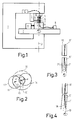
- Fig. 1 shows the basic structure of a measuring arrangement according to the invention.
- Fig. 3 shows a sensor optical fiber whose axis is directed obliquely to the mechanical axis of rotation.
- FIG. 4 shows the arrangement according to FIG. 3 after alignment of the optical axis of the optical fiber to be measured in the mechanical axis of rotation.
- a commercially available form measuring machine was used to carry out the method according to the invention, on the frame 1 of which a rotary table 2 is mounted precisely and with a radial run-out deviation of less than 40 nm.
- a distance sensor 3 is fastened, the button 4 of which scans the surface of the plug pin 5, which is clamped in a holder 6 such that the optical fiber 7 running in the plug pin 5 initially approximately in the mechanical axis of rotation 10 of the turntable 2 runs.
- the other end of the FO 7 is coupled to an optical transmitter 8, for example a laser diode.
- the holder can be moved in the plane of the turntable 2 in two mutually perpendicular coordinate directions by manipulators 9, only one of which is shown.
- a sensor optical fiber 11 is attached to the upper arm of the frame 1 and guided to an optical receiver 12.
- an FO 7 arranged eccentrically to the geometric center axis of the connector pin 5 is drawn in the end position to be adjusted, in which it is aligned as precisely as possible coaxially to the mechanical axis of rotation 10.
- the plug pin 5 is rotated by motor rotation of the turntable 2 with about 5 min ⁇ 1.
- the distance values measured over the entire circumference by the probe arm 3 and related to the position of the mechanical axis of rotation are evaluated to determine a hypothetical circumferential circle of the cylindrical surface of the plug pin 5.
- the distance between the center of the hypothetical circle and the mechanical axis of rotation 10 is then the eccentric offset of the optical fiber 7 to be determined.
- the optical axis 13 of the sensor optical fiber 11 is arranged at a fixed distance e 'from the mechanical axis of rotation 10. If the optical axis of the to be measured LWL 7 after clamping the connector pin 5 in the holder 6 is eccentrically next to the mechanical axis of rotation 10 by the value e, so when the turntable 2 rotates on the dashed circle with the radius e in the area of the enveloping circle 16, it moves the end faces of the optical fiber 7 can assume the extreme positions indicated by the circumferential circles 14 and 15 relative to the circumferential circle 17 of the sensor optical fiber 11.
- the light output from the optical transmitter 8 to the optical receiver 12 fluctuates in accordance with the relative position of the transmitter and sensor LWL.
- the optical fiber 7 is shifted by means of the manipulators 9 until the fluctuation of this light output reaches a minimum or the value "zero". This is the case if the value e according to FIG. 2 assumes the value "zero", that is to say if, as desired, the offset between the optical axis of the optical fiber 7 and the mechanical axis of rotation 10 is no longer present.
- the optical axes of the FO 7 and 11 run exactly parallel to the mechanical axis of rotation 10.
- the optical axes of optical fibers inserted in connector pins can also run at an angle to the center line of a connector pin. Such an inclination can be measured if the optical axis of the sensor optical fiber 11 'according to Figures 3 and 4 is arranged inclined to the mechanical axis of rotation.
- the angular position of the connector pin 5 ' is shifted until the position shown in FIG. 4 is reached, in which the optical fiber 7' is aligned as precisely as possible coaxially with the mechanical axis of rotation 10. This is the case if a minimum of light fluctuations is detected by the receiver 12 when the turntable 2 is rotated.
- the sensor LWL 11 and the LWL 7 to be measured should have diameters of approximately the same size if possible. However, since the adjustment accuracy depends only insignificantly on the diameter ratio, fiber optics can also be measured, the diameter of which deviate considerably from that of the sensor 11.
- the offset e '(Fig. 2) of the sensor optical fiber 11 to the mechanical axis of rotation 10 should be in order to achieve a high sensitivity in the range of 0.5 to 1.5 times the core diameter of the optical fiber 7 to be measured. However, such an offset need not be specified with great accuracy.
- the optical fibers 11 and 7 were each single-mode optical fibers with a core diameter of 9 ⁇ m.
- the axis offset e 'of the sensor FO 11 to the mechanical axis of rotation 10 was 10 ⁇ m.
- the optical axes of the FO 7 can be adjusted with an error of less than 10 nm into the mechanical axis of rotation 10. No high requirements have to be placed on the temporal constancy of the transmission power of the optical transmitter 8, since no absolute values of the optical power need to be measured when adjusting the optical fiber 7 to be measured.
- the fluctuation amplitude of the light output of the receiver 12 can also be used directly as a measure of the eccentricity of an optical fiber to be determined. Then the plug pin 5 is clamped coaxially to the mechanical axis of rotation 10. Provided the light output of the optical transmitter 8 is constant, the fluctuation amplitude of the display of the optical receiver 12 is clearly dependent on the eccentricity e of the optical fiber 7 to be measured, so that the eccentricity e can be read off directly after appropriate calibration.
- a direct measuring method does not allow extreme measuring accuracy, since the measured value depends on the constancy of the transmitted light output.
- Another source of error can be contamination of the end faces of the FO 7 and 11.
- a method is particularly simple and therefore well suited for control measurements to check the manufacturing quality.
Landscapes
- Physics & Mathematics (AREA)
- General Physics & Mathematics (AREA)
- Optics & Photonics (AREA)
- Length Measuring Devices By Optical Means (AREA)
- Testing Of Optical Devices Or Fibers (AREA)
- Mechanical Coupling Of Light Guides (AREA)
Claims (8)
caractérisé en ce que le centre optique de la face avant du guide d'ondes lumineuses (7, 7′) est porté dans l'axe de rotation mécanique (10) d'un détecteur de distance (3) explorant la face latérale du contact mâle (5, 5′), qu'une source lumineuse (8) respectivement un récepteur de lumière couplé optiquement au guide d'ondes lumineuses (7, 7′) et tournant de façon excentrique autour de l'axe de rotation mécanique est disposée vis-à-vis de la face avant du contact mâle (5, 5′) et que le contact mâle (5, 5′) est déplacé dans une position telle que l'amplitude d'oscillation, mesurée pendant la rotation de la source lumineuse (8) respectivement du récepteur de lumière, de la puissance lumineuse couplée à partir de la source lumineuse (8) dans le guide d'ondes lumineuses respectivement à partir du guide d'ondes lumineuses dans le récepteur de lumière (12) atteint un minimum et qu'ensuite l'excentricité du guide d'ondes lumineuses est déterminée à partir des valeurs de mesure déterminées pendant la rotation relative du détecteur de distance (3) le long de la surface latérale du contact mâle (5, 5′).
caractérisé en ce que le centre optique de la face avant du guide d'ondes lumineuses (7, 7′) est porté dans l'axe de rotation mécanique (10) d'un détecteur de distance explorant la surface latérale du contact mâle (5, 5′) qu'une source lumineuse respectivement un récepteur de lumière (12) disposé de façon excentrique par rapport à l'axe de rotation mécanique (10) est disposée stationnairement vis-à-vis de la face avant du guide d'ondes lumineuses (7, 7′) disposé dans le contact mâle (5, 5′) et que le contact mâle (5, 5′) disposé sur une fixation (2) pouvant tourner autour de l'axe de rotation mécanique (10) est aligné de façon que l'amplitude d'oscillation, mesurée pendant la rotation de la fixation, de la puissance lumineuse introduite à partir de la source lumineuse (8) dans le guide d'ondes lumineuses respectivement à partir du guide d'ondes lumineuses dans le récepteur de lumière (12) atteigne un minimum et qu'ensuite l'excentricité du guide d'ondes lumineuses est déterminée à partir des valeurs de mesure déterminées pendant la rotation relative du détecteur de distance (3) le long de la surface latérale du contact mâle (5, 5′).
caractérisé en ce que le rayonnement provenant de la source lumineuse (11) respectivement émis vers le récepteur de lumière (12) est dirigé par l'intermédiaire d'un guide d'ondes lumineuses - capteur (11) sur le guide d'ondes lumineuses (7, 7′) disposé dans le contact mâle (5, 5′).
caractérisé en ce que l'axe de faisceau du guide d'ondes lumineuses - capteur (11) s'étend de façon inclinée par rapport à l'axe de rotation mécanique (10) et que la direction (17) de l'axe du contact mâle (5, 5′) est portée dans une position angulaire par rapport à l'axe de rotation mécanique (10) telle que l'amplitude d'oscillation de la puissance lumineuse atteint un minimum.
caractérisé en ce que le contact mâle (5) est d'abord décalé parallèlement à l'axe de rotation mécanique (10) jusqu'à ce que la part dépendant de l'angle de rotation de la puissance lumineuse introduite atteigne un minimum et qu'ensuite la position angulaire du contact mâle (5′) est décalée par rapport à l'axe de rotation mécanique (10), tout en maintenant la position de sa face avant, de façon que la part dépendant de l'angle de rotation de la puissance lumineuse introduite atteigne pratiquement la valeur "zéro".
caractérisé en ce qu'un guide d'ondes lumineuses - capteur (11) conduit à un récepteur optique (12) est relié rigidement au boîtier de palier (1) de la table rotative (2) de façon que son axe optique soit excentrique par rapport à l'axe de rotation mécanique ( 10) de la table rotative (2).
caractérisé en ce que l'axe du guide d'ondes lumineuses (capteur 11) est dirigé de façon inclinée par rapport à l'axe de rotation mécanique (10) et en ce que des moyens sont prévus pour le décalage angulaire de la direction axiale du contact mâle.
caractérisé en ce que le contact mâle (5, 5′) est tourné autour de son axe géométrique (17), que vis-à-vis de la face avant du guide d'ondes lumineuses (7, 7′) à mesurer est disposé un guide d'ondes lumineuses - capteur (11) pratiquement parallèlement à l'axe du contact mâle, que son axe optique est décalé par rapport à l'axe de rotation mécanique (10) du contact mâle et que l'amplitude d'oscillation de la puissance lumineuse introduite à partir du guide d'ondes lumineuses (7, 7′) à mesurer dans le guide d'ondes lumineuses - capteur (11), respectivement inversement, est mesurée comme mesure pour l'excentricité.
Applications Claiming Priority (2)
| Application Number | Priority Date | Filing Date | Title |
|---|---|---|---|
| DE3810057A DE3810057A1 (de) | 1988-03-25 | 1988-03-25 | Verfahren zur messung der exzentrizitaet eines in einem zylindrischen steckerstift eingebetteten lichtwellenleiters |
| DE3810057 | 1988-03-25 |
Publications (2)
| Publication Number | Publication Date |
|---|---|
| EP0335437A1 EP0335437A1 (fr) | 1989-10-04 |
| EP0335437B1 true EP0335437B1 (fr) | 1992-03-04 |
Family
ID=6350639
Family Applications (1)
| Application Number | Title | Priority Date | Filing Date |
|---|---|---|---|
| EP89200691A Expired - Lifetime EP0335437B1 (fr) | 1988-03-25 | 1989-03-20 | Procédé de mesure de l'excentricité d'un guide d'ondes lumineuses logé dans un contact mâle cylindrique |
Country Status (4)
| Country | Link |
|---|---|
| US (1) | US4994679A (fr) |
| EP (1) | EP0335437B1 (fr) |
| JP (1) | JPH01277731A (fr) |
| DE (2) | DE3810057A1 (fr) |
Families Citing this family (11)
| Publication number | Priority date | Publication date | Assignee | Title |
|---|---|---|---|---|
| DE3824255A1 (de) * | 1988-07-14 | 1990-01-18 | Siemens Ag | Verfahren und vorrichtung zur exzentrizitaetsmessung |
| JPH04323510A (ja) * | 1991-04-23 | 1992-11-12 | Fujikura Ltd | 光ファイバの曲率測定方法 |
| US6918269B2 (en) * | 2001-05-01 | 2005-07-19 | Phillip Hua-Kuan Wang | Optical fiber aligning method |
| WO2008031706A2 (fr) * | 2006-09-13 | 2008-03-20 | Diamond Sa | Dispositif et procédé de mesure de la concentricité d'un guide d'ondes optiques maintenu dans une pointe de contact |
| DE102007012268A1 (de) * | 2007-03-08 | 2008-09-11 | Schmid Technology Systems Gmbh | Verfahren zur Herstellung einer Solarzelle sowie damit hergestellte Solarzelle |
| WO2015095169A1 (fr) | 2013-12-19 | 2015-06-25 | Corning Optical Communications LLC | Systèmes et procédés de mesure de concentricité ferrule-âme |
| US9196940B2 (en) * | 2014-03-07 | 2015-11-24 | Raytheon Company | Waveguide mechanical phase adjuster |
| EP3215822B1 (fr) * | 2014-11-07 | 2020-10-28 | Commscope Asia Holdings B.V. | Procédés pour mesurer des fibres, par exemple pour des mesures géométriques de fibres multimodales |
| US12225289B2 (en) | 2021-05-17 | 2025-02-11 | Corning Research & Development Corporation | Precision non-contact core imaging of fiber optic assemblies |
| WO2023055617A1 (fr) | 2021-09-29 | 2023-04-06 | Corning Research & Development Corporation | Mesure de l'affaiblissement de transmission en mode relatif d'un câble à fibres optiques équipé de connecteurs |
| CN115672769B (zh) * | 2022-11-14 | 2025-02-14 | 杭州中欣晶圆半导体股份有限公司 | 一种自动对硅片进行定位和吸附的检测装置及使用方法 |
Family Cites Families (5)
| Publication number | Priority date | Publication date | Assignee | Title |
|---|---|---|---|---|
| DE2159327C3 (de) * | 1971-11-30 | 1975-03-20 | Licentia Patent-Verwaltungs-Gmbh, 6000 Frankfurt | Vorrichtung zur Justierung zweier optischer Bauelemente |
| US4215937A (en) * | 1979-01-29 | 1980-08-05 | International Telephone And Telegraph Corporation | Method and apparatus for detecting optimum alignment of optical fibers in a connector arrangement |
| FR2526935A1 (fr) * | 1982-05-14 | 1983-11-18 | Thomson Csf | Procede et dispositif de mesure simultanee de caracteristiques geometriques d'une fibre optique |
| ATE71740T1 (de) * | 1985-06-20 | 1992-02-15 | Diamond Sa | Verfahren und vorrichtung zum zentrieren des kerns einer lichtleitfaser in einem lichtleiterendstueck. |
| US4775947A (en) * | 1986-06-17 | 1988-10-04 | Westinghouse Electric Corp. | Method of providing a visual representation of the runout of a shaft |
-
1988
- 1988-03-25 DE DE3810057A patent/DE3810057A1/de not_active Withdrawn
-
1989
- 1989-02-28 US US07/316,733 patent/US4994679A/en not_active Expired - Fee Related
- 1989-03-20 DE DE8989200691T patent/DE58900888D1/de not_active Expired - Lifetime
- 1989-03-20 EP EP89200691A patent/EP0335437B1/fr not_active Expired - Lifetime
- 1989-03-22 JP JP1067770A patent/JPH01277731A/ja active Pending
Also Published As
| Publication number | Publication date |
|---|---|
| DE3810057A1 (de) | 1989-10-05 |
| EP0335437A1 (fr) | 1989-10-04 |
| JPH01277731A (ja) | 1989-11-08 |
| US4994679A (en) | 1991-02-19 |
| DE58900888D1 (de) | 1992-04-09 |
Similar Documents
| Publication | Publication Date | Title |
|---|---|---|
| DE69421166T2 (de) | Bestimmung des winkelversutzes zwischen optischen fasern mit optischer, axialer asymmetrie und ausrichtung und spleissen von solchen fasern | |
| EP0335437B1 (fr) | Procédé de mesure de l'excentricité d'un guide d'ondes lumineuses logé dans un contact mâle cylindrique | |
| DE3429947C2 (fr) | ||
| DE69425659T2 (de) | Gerät zur messung abmessungen eines objektes | |
| DE3232904C2 (fr) | ||
| DE69002565T2 (de) | Verfahren und Einrichtung für die geometrische Charakterisierung durchsichtiger Röhren. | |
| DE19523742A1 (de) | Ausrichtverfahren für optische Fasern, Halteanordnung hierfür sowie Verbindung und Array mit ausgerichteten optischen Fasern | |
| DE3733549C2 (fr) | ||
| DE69610200T2 (de) | Opto-elektronischer messapparat für die verifikation von lineardimensionen | |
| DE4430063A1 (de) | Lichtleitfaserfassung und Verfahren zu deren Herstellung | |
| DE3630163A1 (de) | Zentriervorrichung zum zentrieren von lichtleiter-fasern waehrend des schweissens | |
| DE4030994A1 (de) | Pruefeinrichtung fuer rotationssymmetrische werkstuecke | |
| DE3411121C2 (fr) | ||
| DE69224482T2 (de) | Vorrichtung für die herstellung von polarisationserhaltenden schmelzkopplern | |
| DE3532047A1 (de) | Einrichtung zum erfassen der radialen intensitaetsverteilung einer laserstrahlung | |
| CH680020A5 (fr) | ||
| DE2626243C2 (de) | Justierung von optischen Fasern in Koppelelementen | |
| US5379112A (en) | Process for relative measurement of the center-line of an aperture and the center-line of a cylindrical outline | |
| DE69125907T2 (de) | Verfahren zur Herstellung von Faseroptischen Kollinatoren | |
| DE102016102971A1 (de) | Linseneinrichtung für variablen Arbeitsabstand, Beleuchtungsbaugruppe, Koordinatenmessgerät und Verfahren | |
| DE19526442A1 (de) | Faseroptischer Vielfachschalter | |
| DE3233101C2 (de) | Kolbenmeßmaschine | |
| EP0246691A2 (fr) | Dispositif de mesure de l'atténuation en transmission d'une fibre optique | |
| DE3437412A1 (de) | Beruehrungslose, optische laengenmesseinrichtung | |
| DE2945229C2 (de) | Einrichtung zur berührungslosen Schwingungsmessung mit Hilfe des Laser-Dopplereffekts |
Legal Events
| Date | Code | Title | Description |
|---|---|---|---|
| PUAI | Public reference made under article 153(3) epc to a published international application that has entered the european phase |
Free format text: ORIGINAL CODE: 0009012 |
|
| AK | Designated contracting states |
Kind code of ref document: A1 Designated state(s): CH DE ES FR GB IT LI |
|
| 17P | Request for examination filed |
Effective date: 19900328 |
|
| 17Q | First examination report despatched |
Effective date: 19910222 |
|
| GRAA | (expected) grant |
Free format text: ORIGINAL CODE: 0009210 |
|
| AK | Designated contracting states |
Kind code of ref document: B1 Designated state(s): CH DE ES FR GB IT LI |
|
| PG25 | Lapsed in a contracting state [announced via postgrant information from national office to epo] |
Ref country code: ES Free format text: THE PATENT HAS BEEN ANNULLED BY A DECISION OF A NATIONAL AUTHORITY Effective date: 19920304 |
|
| REF | Corresponds to: |
Ref document number: 58900888 Country of ref document: DE Date of ref document: 19920409 |
|
| ITF | It: translation for a ep patent filed | ||
| ET | Fr: translation filed | ||
| GBT | Gb: translation of ep patent filed (gb section 77(6)(a)/1977) | ||
| PLBE | No opposition filed within time limit |
Free format text: ORIGINAL CODE: 0009261 |
|
| STAA | Information on the status of an ep patent application or granted ep patent |
Free format text: STATUS: NO OPPOSITION FILED WITHIN TIME LIMIT |
|
| 26N | No opposition filed | ||
| PGFP | Annual fee paid to national office [announced via postgrant information from national office to epo] |
Ref country code: CH Payment date: 19940621 Year of fee payment: 6 |
|
| PG25 | Lapsed in a contracting state [announced via postgrant information from national office to epo] |
Ref country code: LI Effective date: 19950331 Ref country code: CH Effective date: 19950331 |
|
| PGFP | Annual fee paid to national office [announced via postgrant information from national office to epo] |
Ref country code: GB Payment date: 19950331 Year of fee payment: 7 Ref country code: FR Payment date: 19950331 Year of fee payment: 7 |
|
| ITPR | It: changes in ownership of a european patent |
Owner name: CAMBIO RAGIONE SOCIALE;PHILIPS ELECTRONICS N.V. |
|
| PGFP | Annual fee paid to national office [announced via postgrant information from national office to epo] |
Ref country code: DE Payment date: 19950529 Year of fee payment: 7 |
|
| REG | Reference to a national code |
Ref country code: CH Ref legal event code: PL |
|
| PG25 | Lapsed in a contracting state [announced via postgrant information from national office to epo] |
Ref country code: GB Effective date: 19960320 |
|
| GBPC | Gb: european patent ceased through non-payment of renewal fee |
Effective date: 19960320 |
|
| PG25 | Lapsed in a contracting state [announced via postgrant information from national office to epo] |
Ref country code: FR Effective date: 19961129 |
|
| PG25 | Lapsed in a contracting state [announced via postgrant information from national office to epo] |
Ref country code: DE Effective date: 19961203 |
|
| REG | Reference to a national code |
Ref country code: FR Ref legal event code: ST |
|
| PG25 | Lapsed in a contracting state [announced via postgrant information from national office to epo] |
Ref country code: IT Free format text: LAPSE BECAUSE OF NON-PAYMENT OF DUE FEES;WARNING: LAPSES OF ITALIAN PATENTS WITH EFFECTIVE DATE BEFORE 2007 MAY HAVE OCCURRED AT ANY TIME BEFORE 2007. THE CORRECT EFFECTIVE DATE MAY BE DIFFERENT FROM THE ONE RECORDED. Effective date: 20050320 |