EP0335437B1 - Process for measuring the excentricity of an optical fibre cable embedded in a cylindrical guide pin - Google Patents
Process for measuring the excentricity of an optical fibre cable embedded in a cylindrical guide pin Download PDFInfo
- Publication number
- EP0335437B1 EP0335437B1 EP89200691A EP89200691A EP0335437B1 EP 0335437 B1 EP0335437 B1 EP 0335437B1 EP 89200691 A EP89200691 A EP 89200691A EP 89200691 A EP89200691 A EP 89200691A EP 0335437 B1 EP0335437 B1 EP 0335437B1
- Authority
- EP
- European Patent Office
- Prior art keywords
- rotation
- waveguide
- connector pin
- mechanical axis
- axis
- Prior art date
- Legal status (The legal status is an assumption and is not a legal conclusion. Google has not performed a legal analysis and makes no representation as to the accuracy of the status listed.)
- Expired - Lifetime
Links
- 238000000034 method Methods 0.000 title claims description 25
- 239000013307 optical fiber Substances 0.000 title description 41
- 230000003287 optical effect Effects 0.000 claims description 36
- 230000001419 dependent effect Effects 0.000 claims description 6
- 230000005855 radiation Effects 0.000 claims description 2
- 239000000835 fiber Substances 0.000 description 18
- 238000005259 measurement Methods 0.000 description 4
- 230000005540 biological transmission Effects 0.000 description 2
- 238000011109 contamination Methods 0.000 description 1
- 238000006073 displacement reaction Methods 0.000 description 1
- 238000004519 manufacturing process Methods 0.000 description 1
- 239000000523 sample Substances 0.000 description 1
- 230000035945 sensitivity Effects 0.000 description 1
- 230000002123 temporal effect Effects 0.000 description 1
Images
Classifications
-
- G—PHYSICS
- G02—OPTICS
- G02B—OPTICAL ELEMENTS, SYSTEMS OR APPARATUS
- G02B6/00—Light guides; Structural details of arrangements comprising light guides and other optical elements, e.g. couplings
- G02B6/24—Coupling light guides
- G02B6/36—Mechanical coupling means
- G02B6/38—Mechanical coupling means having fibre to fibre mating means
- G02B6/3807—Dismountable connectors, i.e. comprising plugs
- G02B6/3833—Details of mounting fibres in ferrules; Assembly methods; Manufacture
- G02B6/3834—Means for centering or aligning the light guide within the ferrule
- G02B6/3843—Means for centering or aligning the light guide within the ferrule with auxiliary facilities for movably aligning or adjusting the fibre within its ferrule, e.g. measuring position or eccentricity
Definitions
- the invention relates to a method for measuring the eccentricity of an optical waveguide (LW) embedded in a cylindrical plug pin, and to an arrangement for carrying out this method according to the preamble of patent claim 6.
- Such a method is known from GB-A 20 40 495.
- the end areas of the LWL to be convoluted must be firmly and centrally embedded in cylindrical connector pins.
- the optical axes of the coupled LWL must be aligned as precisely as possible. Since the outer surface of the connector serves as a reference surface for the alignment of the connector, the eccentricity, for example, of a single-mode fiber-optic cable must be less than 0.5 ⁇ m if you want to achieve sufficiently small connector losses. Control measurements must be carried out with an accuracy of at least 100 nm. On the diameter of the connector sleeve e.g. Related to 1.25 mm, this means a relative accuracy of 8 x 10 ⁇ 5.
- Measuring methods which are known for measuring the eccentricity of the core of an optical fiber relative to its outer surface (e.g. "image sharing technique", company name “Fiber Optic Bulletin No. 10 from Vickers Instruments”) are not suitable for this.
- the invention has for its object to improve the measuring method of the type mentioned and to create a suitable measuring device.
- the optical center of the end face of the optical fiber is brought into the mechanical axis of rotation of a distance sensor scanning the outer surface of the connector pin by an eccentrically rotating around the mechanical axis of rotation relative to the end face of the connector pin.
- a second solution consists in that the optical center of the end face of the optical fiber is brought into the mechanical axis of rotation of a distance sensor scanning the outer surface of the plug pin, that a light transmitter or light receiver arranged eccentrically to the mechanical axis of rotation is arranged in a fixed position relative to the end face of the optical fiber arranged in the plug pin and that the plug pin arranged on a holder rotatable about the mechanical axis of rotation is oriented in such a way that the fluctuation amplitude of the light output coupled from the light transmitter into the optical fiber or from the optical fiber into the light receiver reaches a minimum when the holder rotates, and thereafter out the eccentricity of the optical fiber is determined from the measured values determined during the relative rotation of the distance sensor along the lateral surface of the plug pin.
- a particularly simple device can be constructed in a robust manner for such a method.
- a prerequisite for achieving the desired accuracy is, of course, that the relative rotation of the distance sensor around the circumference of the plug pin is effected by means of a highly precise bearing.
- Commercially available shape measuring machines suitable for the present invention have rotating spindles whose runout deviation is less than 40 nm.
- buttons or, for example, optically acting devices of a known type are suitable as distance sensors. Devices of this type measuring sufficiently precisely in the nm range are commercially available.
- the optical center - generally the center of the end face of a core of an optical fiber - must be brought into the mechanical axis of rotation with high accuracy, namely with an offset of less than 10 nm if possible.
- This is advantageously possible by means of optical adjustment methods, in which the light passage from the optical fiber arranged in the plug pin to an approximately coaxial sensor optical fiber - or vice versa - serves as a criterion for reaching the target position.
- Such adjustment methods are widely known for the adjustment of two optical fibers to be connected.
- the radiation from the light transmitter or to the light receiver is directed via a sensor fiber optic cable to the fiber optic cable arranged in the connector pin. Then the direction of reception or transmission can be clearly defined and there is a narrow beam of light.
- a possible angular offset of the optical axis of the fiber optic cable to the center line of the connector pin can be measured by the fact that the beam axis of the sensor fiber optic cable is inclined to the mechanical axis of rotation and that the axial direction of the connector pin is brought into such an angular position to the mechanical axis of rotation that the angle of rotation-dependent portion of the coupled light output reached a minimum.
- the connector pin is first shifted axially parallel to the mechanical axis of rotation until the angle-dependent portion of the coupled light output reaches a minimum, and that the angular position of the connector pin is then maintained the position of its end face is shifted such that the angle-dependent portion of the coupled light output practically reaches the value "zero".
- An alternative method, particularly suitable for control measurements, for solving the problem mentioned at the outset is characterized in that the plug pin is rotated about the geometric central axis that a sensor fiber optic cable is arranged approximately axially parallel to the end face of the connector pin to be measured, such that its optical axis is offset from the mechanical axis of rotation of the connector pin, and that the fluctuation amplitude of the fiber optic cable to be measured in the Sensor-LWL or vice versa coupled light output is measured as a measure of the eccentricity.
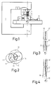
- Fig. 1 shows the basic structure of a measuring arrangement according to the invention.
- Fig. 3 shows a sensor optical fiber whose axis is directed obliquely to the mechanical axis of rotation.
- FIG. 4 shows the arrangement according to FIG. 3 after alignment of the optical axis of the optical fiber to be measured in the mechanical axis of rotation.
- a commercially available form measuring machine was used to carry out the method according to the invention, on the frame 1 of which a rotary table 2 is mounted precisely and with a radial run-out deviation of less than 40 nm.
- a distance sensor 3 is fastened, the button 4 of which scans the surface of the plug pin 5, which is clamped in a holder 6 such that the optical fiber 7 running in the plug pin 5 initially approximately in the mechanical axis of rotation 10 of the turntable 2 runs.
- the other end of the FO 7 is coupled to an optical transmitter 8, for example a laser diode.
- the holder can be moved in the plane of the turntable 2 in two mutually perpendicular coordinate directions by manipulators 9, only one of which is shown.
- a sensor optical fiber 11 is attached to the upper arm of the frame 1 and guided to an optical receiver 12.
- an FO 7 arranged eccentrically to the geometric center axis of the connector pin 5 is drawn in the end position to be adjusted, in which it is aligned as precisely as possible coaxially to the mechanical axis of rotation 10.
- the plug pin 5 is rotated by motor rotation of the turntable 2 with about 5 min ⁇ 1.
- the distance values measured over the entire circumference by the probe arm 3 and related to the position of the mechanical axis of rotation are evaluated to determine a hypothetical circumferential circle of the cylindrical surface of the plug pin 5.
- the distance between the center of the hypothetical circle and the mechanical axis of rotation 10 is then the eccentric offset of the optical fiber 7 to be determined.
- the optical axis 13 of the sensor optical fiber 11 is arranged at a fixed distance e 'from the mechanical axis of rotation 10. If the optical axis of the to be measured LWL 7 after clamping the connector pin 5 in the holder 6 is eccentrically next to the mechanical axis of rotation 10 by the value e, so when the turntable 2 rotates on the dashed circle with the radius e in the area of the enveloping circle 16, it moves the end faces of the optical fiber 7 can assume the extreme positions indicated by the circumferential circles 14 and 15 relative to the circumferential circle 17 of the sensor optical fiber 11.
- the light output from the optical transmitter 8 to the optical receiver 12 fluctuates in accordance with the relative position of the transmitter and sensor LWL.
- the optical fiber 7 is shifted by means of the manipulators 9 until the fluctuation of this light output reaches a minimum or the value "zero". This is the case if the value e according to FIG. 2 assumes the value "zero", that is to say if, as desired, the offset between the optical axis of the optical fiber 7 and the mechanical axis of rotation 10 is no longer present.
- the optical axes of the FO 7 and 11 run exactly parallel to the mechanical axis of rotation 10.
- the optical axes of optical fibers inserted in connector pins can also run at an angle to the center line of a connector pin. Such an inclination can be measured if the optical axis of the sensor optical fiber 11 'according to Figures 3 and 4 is arranged inclined to the mechanical axis of rotation.
- the angular position of the connector pin 5 ' is shifted until the position shown in FIG. 4 is reached, in which the optical fiber 7' is aligned as precisely as possible coaxially with the mechanical axis of rotation 10. This is the case if a minimum of light fluctuations is detected by the receiver 12 when the turntable 2 is rotated.
- the sensor LWL 11 and the LWL 7 to be measured should have diameters of approximately the same size if possible. However, since the adjustment accuracy depends only insignificantly on the diameter ratio, fiber optics can also be measured, the diameter of which deviate considerably from that of the sensor 11.
- the offset e '(Fig. 2) of the sensor optical fiber 11 to the mechanical axis of rotation 10 should be in order to achieve a high sensitivity in the range of 0.5 to 1.5 times the core diameter of the optical fiber 7 to be measured. However, such an offset need not be specified with great accuracy.
- the optical fibers 11 and 7 were each single-mode optical fibers with a core diameter of 9 ⁇ m.
- the axis offset e 'of the sensor FO 11 to the mechanical axis of rotation 10 was 10 ⁇ m.
- the optical axes of the FO 7 can be adjusted with an error of less than 10 nm into the mechanical axis of rotation 10. No high requirements have to be placed on the temporal constancy of the transmission power of the optical transmitter 8, since no absolute values of the optical power need to be measured when adjusting the optical fiber 7 to be measured.
- the fluctuation amplitude of the light output of the receiver 12 can also be used directly as a measure of the eccentricity of an optical fiber to be determined. Then the plug pin 5 is clamped coaxially to the mechanical axis of rotation 10. Provided the light output of the optical transmitter 8 is constant, the fluctuation amplitude of the display of the optical receiver 12 is clearly dependent on the eccentricity e of the optical fiber 7 to be measured, so that the eccentricity e can be read off directly after appropriate calibration.
- a direct measuring method does not allow extreme measuring accuracy, since the measured value depends on the constancy of the transmitted light output.
- Another source of error can be contamination of the end faces of the FO 7 and 11.
- a method is particularly simple and therefore well suited for control measurements to check the manufacturing quality.
Landscapes
- Physics & Mathematics (AREA)
- General Physics & Mathematics (AREA)
- Optics & Photonics (AREA)
- Length Measuring Devices By Optical Means (AREA)
- Mechanical Coupling Of Light Guides (AREA)
- Testing Of Optical Devices Or Fibers (AREA)
Description
Die Erfindung bezieht sich auf ein Verfahren zur Messung der Exzentrizität eines in einem zylindrischen Steckerstift eingebetteten Lichtwellenleiters (LW) sowie auf eine Anordnung zur Durchführung dieses Verfahrens gemäß dem Oberbegriff des Patentanspruchs 6.
Ein derartiges Verfahren ist durch die GB-A 20 40 495 bekannt.The invention relates to a method for measuring the eccentricity of an optical waveguide (LW) embedded in a cylindrical plug pin, and to an arrangement for carrying out this method according to the preamble of
Such a method is known from GB-A 20 40 495.
Bei Steckverbindungen von Lichtwellenleitern (LWL) müssen die zu konpelnden Endbereiche der LWL in zylindrischen Steckerstiften fest und zentrisch eingebettet sein. Die optischen Achsen der gekoppelten LWL müssen möglichst genau fluchten. Da die Mantelfläche des steckers als Bezugsfläche für die Ausrichtung der Steckverbindung dient, muß die Exzentrizität beispielsweise eines Monomode-LWL kleiner als 0,5 µm sein, wenn man genügend kleine Steckerdämpfungen erreichen will. Bei Kontrollmessungen muß mit einer Genauigkeit von mindestens 100 nm gemessen werden. Auf den Durchmesser der Steckerhülse von z.B. 1,25 mm bezogen bedeutet das eine relative Genauigkeit von 8 x 10⁻⁵.In the case of plug-in connections of optical fibers (LWL), the end areas of the LWL to be convoluted must be firmly and centrally embedded in cylindrical connector pins. The optical axes of the coupled LWL must be aligned as precisely as possible. Since the outer surface of the connector serves as a reference surface for the alignment of the connector, the eccentricity, for example, of a single-mode fiber-optic cable must be less than 0.5 µm if you want to achieve sufficiently small connector losses. Control measurements must be carried out with an accuracy of at least 100 nm. On the diameter of the connector sleeve e.g. Related to 1.25 mm, this means a relative accuracy of 8 x 10⁻⁵.
Meßverfahren, die für die Messung der Exzentrizität des Kerns eines LWL relativ zu seiner äußeren Mantelfläche bekannt sind (z.B. "image sharing technique", Firmenschrift "Fibre Optic Bulletin nr. 10 der Firma Vickers Instruments"), sind dafür nicht geeignet.Measuring methods which are known for measuring the eccentricity of the core of an optical fiber relative to its outer surface (e.g. "image sharing technique", company name "Fiber Optic Bulletin No. 10 from Vickers Instruments") are not suitable for this.
Der Erfindung liegt die Aufgabe zugrunde, das Meßverfahren der eingangs genannten Art zu verbessern und eine geeignete Meßvorrichtung zu schaffen.The invention has for its object to improve the measuring method of the type mentioned and to create a suitable measuring device.
Gemäß einer ersten Lösung ist vorgesehen, daß der optische Mittelpunkt der Stirnfläche des LWL dadurch in die mechanische Drehachse eines die Mantelfläche des Steckerstifts abtastenden Abstandsfühlers gebracht wird, daß gegenüber der Stirnfläche des steckerstifts eine exzentrisch um die mechanische Drehachse rotierende, mit dem LWL optisch gekoppelte Lichtquelle bzw. ein Lichtempfänger angeordnet ist, und daß der steckerstift in eine derartige Lage verschoben wird, daß die bei Drehung der Lichtquelle bzw. des Lichtempfängers gemessene Schwankungsamplitude der vom Lichtsender in den LWL bzw. vom LWL and den Lichtempfänger eingekoppelten Lichtleistung ein Minimum erreicht, und daß danach aus den bei der Relativdrehung des Abstandsfühlers entlang der Mantelfläche des Steckerstifts ermittelten Meßwerten die Exzentrizität des LWL ermittelt wird.According to a first solution, it is provided that the optical center of the end face of the optical fiber is brought into the mechanical axis of rotation of a distance sensor scanning the outer surface of the connector pin by an eccentrically rotating around the mechanical axis of rotation relative to the end face of the connector pin. is arranged optically coupled with the fiber optic light source or a light receiver, and that the plug pin is moved into such a position that the fluctuation amplitude measured when the light source or the light receiver rotates is coupled in by the light transmitter into the fiber optic cable or from the fiber optic cable and the light receiver Light output reaches a minimum, and that the eccentricity of the optical fiber is then determined from the measured values determined during the relative rotation of the distance sensor along the lateral surface of the connector pin.
Eine zweite Lösung besteht darin, daß der optische Mittelpunkt der Stirnfläche des LWL dadurch in die mechanische Drehachse eines die Mantelfläche des Steckerstifts abtastenden Abstandsfühlers gebracht wird, daß gegegenüber der Stirnfläche des im Steckerstift angeordneten LWL ein zur mechanischen Drehachse exzentrisch angeordneter Lichtsender bzw. Lichtempfänger ortsfest angeordnet ist, und daß der auf einer um die mechanische Drehachse drehbare Halterung angeordnete steckerstift derart ausgerichtet ist, daß die bei Drehung der Halterung gemessene Schwankungsamplitude der vom Lichtsender in den LWL bzw. vom LWL in den Lichtempfänger eingekoppelten Lichtleistung ein Minimum erreicht, und daß danach aus den bei der Relativdrehung des Abstandsfühlers entlang der Mantelfläche des Steckerstifts ermittelten Meßwerten die Exzentrizität des LWL ermittelt wird.A second solution consists in that the optical center of the end face of the optical fiber is brought into the mechanical axis of rotation of a distance sensor scanning the outer surface of the plug pin, that a light transmitter or light receiver arranged eccentrically to the mechanical axis of rotation is arranged in a fixed position relative to the end face of the optical fiber arranged in the plug pin and that the plug pin arranged on a holder rotatable about the mechanical axis of rotation is oriented in such a way that the fluctuation amplitude of the light output coupled from the light transmitter into the optical fiber or from the optical fiber into the light receiver reaches a minimum when the holder rotates, and thereafter out the eccentricity of the optical fiber is determined from the measured values determined during the relative rotation of the distance sensor along the lateral surface of the plug pin.
Für ein solches Verfahren läßt sich eine besonders einfache Vorrichtung robust aufbauen.A particularly simple device can be constructed in a robust manner for such a method.
Voraussetzung für das Erreichen der gewünschten Genauigkeit ist natürlich, daß die Relativdrehung des Abstandsfühlers um den Umfang des Steckerstifts mittels einer hochpräzisen Lagerung bewirkt wird. Für die Zwecke der vorliegenden Erfindung geeignete handelsübliche Formmeßmaschinen weisen Drehspindeln auf, deren Rundlaufabweichung weniger als 40 nm beträgt.A prerequisite for achieving the desired accuracy is, of course, that the relative rotation of the distance sensor around the circumference of the plug pin is effected by means of a highly precise bearing. For the purposes Commercially available shape measuring machines suitable for the present invention have rotating spindles whose runout deviation is less than 40 nm.
Als Abstandsfühler sind mechanische Taster oder beispielsweise auch optisch wirkende Geräte bekannter Art geeignet. Genügend genau im nm-Bereich messende Geräte dieser Art sind handelsüblich.Mechanical buttons or, for example, optically acting devices of a known type are suitable as distance sensors. Devices of this type measuring sufficiently precisely in the nm range are commercially available.
Bei der Ermittlung der Exzentrizität des LWL kann eine Vielzahl von über den Umfang des steckerstifts er.mittelten Meßwerten berücksichtigt werden, damit nicht zufällige Unebenheiten der Steckeroberfläche den Meßwert verfälschen.When determining the eccentricity of the fiber optic cable, a large number of measured values determined over the circumference of the plug pin can be taken into account, so that accidental unevenness in the connector surface falsifies the measured value.
Der optische Mittelpunkt - im allgemeinen der Mittelpunkt der stirnfläche eines Kerns eines LWL - muß mit hoher Genauigkeit, nämlich mit einem Versatz von möglichst weniger als 10 nm, in die mechanische Drehachse gebracht werden. Das ist vorteilhaft mittels optischer Justiervprfahren möglich, bei welchen der Lichtdurchgang vom im Steckerstift angeordneten LWL in einen annähernd koaxial dazu angeordneten Sensor-LWL - bzw. umgekehrt - als Kriterium für das Erreichen der Zielposition dient. Derartige Justierverfahren sind vielfältig für die Justierung zweier zu verbindender LWL bekannt.The optical center - generally the center of the end face of a core of an optical fiber - must be brought into the mechanical axis of rotation with high accuracy, namely with an offset of less than 10 nm if possible. This is advantageously possible by means of optical adjustment methods, in which the light passage from the optical fiber arranged in the plug pin to an approximately coaxial sensor optical fiber - or vice versa - serves as a criterion for reaching the target position. Such adjustment methods are widely known for the adjustment of two optical fibers to be connected.
Durch Patent Abstracts of Japan, Sektion E, Band 2, nr. 104, Seite 5452 E 78, Kokai-Nr. 53-69 652 ist ein Verfahren zur Messung der Exzentrizität eines LWL, bei dem der optische Mittelpunkt der Stirnfläche des LWL in die mechanische Drehachse eines die Mantelfläche des LWL abtastenden Abstandsfühlers gebracht wird und bei dem danach aus den bei der Relativdrehung des Abstandsfühlers entlang der Mantelfläche ermittelten Meßwerten die Exzentrizität des LWL ermittelt wird, bekannt. Dabei wird die Lage des optischen Mittelpunkts der Stirnfläche des LWL durch eingeleitetes Licht sichtbar gemacht und die Verschiebung durch ein Mikroskop kontrolliert.Through Patent Abstracts of Japan, Section E,
Es empfiehlt sich, daß die Strahlung vom Lichtsender bzw. zum Lichtempfänger über einen Sensor-LWL auf den im Steckerstift angeordneten LWL gerichtet ist. Dann ist die Empfangs- bzw. Senderichtung eindeutig festlegbar und es ergibt sich ein enges Lichtbündel.It is recommended that the radiation from the light transmitter or to the light receiver is directed via a sensor fiber optic cable to the fiber optic cable arranged in the connector pin. Then the direction of reception or transmission can be clearly defined and there is a narrow beam of light.
Ein eventueller Winkelversatz der optischen Achse des LWL zur Mittellinie des Steckerstifts läßt sich dadurch vermessen, daß die Strahlachse des Sensor-LWL geneigt zur mechanischen Drehachse verläuft und daß die Achsrichtung des Steckerstifts in eine solche Winkellage zur mechanischen Drehachse gebracht wird, daß der drehwinkelabhängige Anteil der eingekoppelten Lichtleistung ein Minimum erreicht.A possible angular offset of the optical axis of the fiber optic cable to the center line of the connector pin can be measured by the fact that the beam axis of the sensor fiber optic cable is inclined to the mechanical axis of rotation and that the axial direction of the connector pin is brought into such an angular position to the mechanical axis of rotation that the angle of rotation-dependent portion of the coupled light output reached a minimum.
Da im allgemeinen sowohl die Exzentrizität als auch der Winkelversatz des LWL gemessen werden müssen, wird bevorzugt, daß der Steckerstift zunächst achsparallel zur mechanischen Drehachse verschoben wird, bis der drehwinkelanhängige Anteil der eingekoppelten Lichtleistung ein Minimum erreicht, und daß danach die Winkellage des Steckerstifts unter Beibehaltung der Lage ihrer Stirnfläche derart verschoben wird, daß der drehwinkelabhängige Anteil der eingekoppelten Lichtleistung praktisch den Wert "Null" erreicht.Since in general both the eccentricity and the angular misalignment of the fiber optic cable must be measured, it is preferred that the connector pin is first shifted axially parallel to the mechanical axis of rotation until the angle-dependent portion of the coupled light output reaches a minimum, and that the angular position of the connector pin is then maintained the position of its end face is shifted such that the angle-dependent portion of the coupled light output practically reaches the value "zero".
In den Asprüchen 6 und 7 sind vorteilhafte Anordnungen zur Ausübung der erfindungsgemäßen Verfahren gekennzeichnet.Advantageous arrangements for carrying out the method according to the invention are characterized in
Ein insbesondere für Kontrollmessungen geeignetes alternatives Verfahren zur Lösung der eingangs genannten Aufgabe ist dadurch gekennzeichnet, daß der Steckerstift um die geometrische Mittelachse gedreht wird, daß gegenüber der Stirnfläche des zu vermessenden Steckerstifts ein Sensor-LWL in etwa achsparallel derart angeordnet wird, daß seine optische Achse gegenüber der mechanischen Drehachse des Steckerstifts versetzt ist, und daß die Schwankungsamplitude der vom zu vermessenden LWL in den Sensor-LWL bzw. umgekehrt eingekoppelten Lichtleistung als maß für die Extentrizitat gemessen wird.An alternative method, particularly suitable for control measurements, for solving the problem mentioned at the outset is characterized in that the plug pin is rotated about the geometric central axis that a sensor fiber optic cable is arranged approximately axially parallel to the end face of the connector pin to be measured, such that its optical axis is offset from the mechanical axis of rotation of the connector pin, and that the fluctuation amplitude of the fiber optic cable to be measured in the Sensor-LWL or vice versa coupled light output is measured as a measure of the eccentricity.
Die Erfindung wird anhand der Beschreibung der Zeichnung näher erläutert.The invention is explained in more detail with reference to the description of the drawing.
Fig. 1 zeigt den Prinzipaufbau einer erfindungsgemäßen Meß-Anordnung.Fig. 1 shows the basic structure of a measuring arrangement according to the invention.
Fig. 2 zeigt mögliche Lagen des zu vermessenden LWL relativ zu einem Sensor-LWL.2 shows possible positions of the optical fiber to be measured relative to a sensor optical fiber.
Fig. 3 zeigt einen Sensor-LWL, dessen Achse schräg zur mechanischen Drehachse gerichtet ist.Fig. 3 shows a sensor optical fiber whose axis is directed obliquely to the mechanical axis of rotation.
Fig. 4 zeigt die Anordnung nach Fig. 3 nach Ausrichtung der optischen Achse des zu vermessenden LWL in die mechanische Drehachse.FIG. 4 shows the arrangement according to FIG. 3 after alignment of the optical axis of the optical fiber to be measured in the mechanical axis of rotation.
Zur Ausübung des erfindungsgemäßen Verfahrens wurde gemäß Fig. 1 eine handelsübliche Formmeßmaschine verwendet, an deren Gestell 1 ein Drehtisch 2 präzise und mit einer Rundlaufabweichung von weniger als 40 nm gelagert ist. Am oberen Arm des Gestells 1 ist ein Abstandsfühler 3 befestigt, dessen Taster 4 die Oberfläche des Steckerstifts 5 abtastet, welche derart in einer Halterung 6 eingespannt ist, daß der im Steckerstift 5 verlaufende LWL 7 zunächst in etwa in der mechanischen Drehachse 10 des Drehtisches 2 verläuft.1, a commercially available form measuring machine was used to carry out the method according to the invention, on the
Das andere Ende des LWL 7 ist an einen optischen Sender 8, beispielsweise eine Laserdiode, angekoppelt.The other end of the
Die Halterung ist durch Manipulatoren 9, von denen lediglich einer gezeichnet ist, in der Ebene des Drehtisches 2 in zwei zueinander senkrechten Koordinatenrichtungen verschiebbar.The holder can be moved in the plane of the
Mit geringem Parallelabstand zu der mechanischen Drehachse 10 ist ein Sensor-LWL 11 am oberen Arm des Gestells 1 befestigt und zu einem optischen Empfänger 12 geführt.With a small parallel distance to the mechanical axis of
In der Figur ist ein außermittig zur geometrischen Mittelachse des Steckerstifts 5 angeordneter LWL 7 in der einzujustierenden Endposition gezeichnet, in welcher er möglichst genau koaxial zur mechanischen Drehachse 10 ausgerichtet ist. In dieser Position wird der Steckerstift 5 durch motorische Drehung des Drehtisches 2 mit etwa 5 min⁻¹ gedreht. Die dabei über den gesamten Umfang vom Tastarm 3 gemessenen, auf die Lage der mechanischen Drehachse bezogenen Abstandswerte werden zur Ermittlung eines hypothetischen Umfangskreises der Zylinderfläche der Steckerstift 5 ausgewertet. Der Abstand des Mittelpunktes des hypothetischen Kreises von der mechanischen Drehachse 10 ist dann der zu ermittelnde exzentrische Versatz des LWL 7.In the figure, an
Das Verfahren zur genauen Justierung der Endfläche des LWL 7 in die mechanische Drehachse 10 wird anhand Figur 2 erläutert.The method for precise adjustment of the end face of the
Die optische Achse 13 des Sensor-LWL 11 ist mit einem festen Abstand e′ zur mechanischen Drehachse 10 angeordnet. Wenn die optische Achse des zu vermessenden LWL 7 nach der Einspannung des Steckerstifts 5 in die Halterung 6 zunächst um den Wert e exzentrisch neben der mechanischen Drehachse 10 liegt, so bewegt sie sich bei Drehung des Drehtisches 2 auf dem gestrichelt gezeichneten Kreis mit dem Radius e im Flächenbereich des Hüllkreises 16. Dabei können die Stirnflächen des LWL 7 die mit den Umfangskreisen 14 und 15 angedeuteten Extremlagen relativ zum Umfangskreis 17 des Sensor-LWL 11 annehmen. Entsprechend der relativen Lage von Sende- und Sensor LWL schwankt die vom optischen Sender 8 zum optischen Empfänger 12 gelangende Lichtleistung. Der LWL 7 wird solange mittels der Manipulatoren 9 verschoben, bis die Schwankung dieser Lichtleistung ein Minimum oder den Wert "Null" erreicht. Das ist dann der Fall, wenn der Wert e nach Figur 2 den Wert "Null" annimmt, wenn also wie angestrebt der Versatz zwischen der optischen Achse des LWL 7 und der mechanischen Drehachse 10 nicht mehr vorhanden ist.The
Bisher wurde stillschweigend vorausgesetzt, daß die optischen Achsen der LWL 7 und 11 genau parallel zur mechanischen Drehachse 10 verlaufen. Die optischen Achsen von in Steckerstiften eingebrachten Lichtwellenleitern können jedoch auch schräg zur Mittellinie eines Steckerstifts verlaufen. Eine solche Schrägstellung läßt sich vermessen, wenn die optische Achse des Sensor-LWL 11′ gemäß den Figuren 3 und 4 zur mechanischen Drehachse geneigt angeordnet wird.So far, it has been tacitly assumed that the optical axes of the
Die optische Achse des im Steckerstift 5′ schräg zu der Mittelachse 18 (Fig. 4) angeordneten LWL 7′ wandert dann bei Drehung des Drehtisches 2 auf einer Kegelfläche.The optical axis of the in the connector pin 5 'obliquely to the central axis 18 (Fig. 4) LWL 7' then migrates when rotating the
In der voll ausgezogenen Position 7′ wird weniger Licht in den LWL 11′ eingekoppelt, als in der gestrichelten Position 7˝ des LWL 7′.In the fully extended position 7 'less light is injected into the fiber 11' than in the dashed position 7 'of the fiber 7'.
Durch Manipulatoren wird die Winkellage des Steckerstifts 5′ solange verschoben, bis die in Figur 4 dargestellte Lage erreicht ist, in welcher der LWL 7′ möglichst genau koaxial zur mechanischen Drehachse 10 ausgerichtet verläuft. Das ist dann der Fall, wenn bei Drehung des Drehtisches 2 ein Minimum der Lichtschwankungen vom Empfänger 12 detektiert wird.By manipulators, the angular position of the connector pin 5 'is shifted until the position shown in FIG. 4 is reached, in which the optical fiber 7' is aligned as precisely as possible coaxially with the mechanical axis of
Die Lage der Zylinderfläche des Steckerstifts 5′ kann dann mittels des Abstandsfühlers durch in mindestens zwei Ebenen erfolgende Messung erfaßt werden.The position of the cylindrical surface of the connector pin 5 'can then be detected by means of the distance sensor by measurement taking place in at least two planes.
In der Paxis wird man zunächst die zentrische Ausrichtung der Innenfläche des LWL 7′ zur mechanischen Achse 10 vornehmen, wobei wegen der Schräglage des LWL 11′ nicht der Wert "Null" der Schwankung der Anzeige des optischen Empfängers 12 erreicht wird, sondern nur ein Minimum. Danach wird die Winkellage des Steckerstifts 5′ unter Beibehaltung der Lage ihrer Stirnfläche in eine Position gemäß Fig. 4 ausgerichtet. In dieser Position wird dann praktisch die Schwankung "Null" der vom Empfänger 12 detektierten Leistung gemessen.In practice you will first make the central alignment of the inner surface of the fiber optic 7 'to the
Der Sensor-LWL 11 und der zu vermessende LWL 7 sollten nach Möglichkeit etwa gleich große Durchmesser haben. Da aber die Justiergenauigkeit nur unwesentlich vom Durchmesserverhältnis abhängt, können auch LWL vermessen werden, deren Durchmesser von demjenigem des Sensors 11 beträchtlich abweichen.The
Der Versatz e′ (Fig. 2) des Sensor-LWL 11 zur mechanischen Drehachse 10 sollte zur Erzielung einer hohen Meßempfindlichkeit im Bereich von 0,5 fachen bis 1,5 fachen des Kerndurchmessers des zu vermessenden LWL 7 betragen. Ein solcher Versatz braucht aber nicht mit großer Genauigkeit vorgegeben zu werden.The offset e '(Fig. 2) of the sensor
Beim beschriebenen Ausführungsbeispiel waren die LWL 11 und 7 jeweils Monomode-LWL mit einem Kerndurchmesser von 9 um. Der Achsversatz e′ des Sensor-LWL 11 zur mechanischen Drehachse 10 betrug 10 µm.In the exemplary embodiment described, the
Mit der in Fig. 1 dargestellten Anordnung können die optischen Achsen des LWL 7 mit einem Fehler von weniger als 10 nm in die mechanische Drehachse 10 justiert werden. An die zeitliche Konstanz der Sendeleistung des optischen Senders 8 brauchen keine hohen Anforderungen gestellt zu werden, da bei der Einjustierung des zu vermessenden LWL 7 keine Absolutwerte der optischen Leistung gemessen werden müssen.With the arrangement shown in FIG. 1, the optical axes of the
Die Schwankungsamplitude der Lichtleistung des Empfängers 12 kann jedoch bei einem alternativen Verfahren auch direkt als Maß für die zu ermittelnde Exzentrizität eines LWL genutzt werden. Dann wird der Steckerstift 5 koaxial zur mechanischen Drehachse 10 eingespannt. Unter der Voraussetzung der Konstanz der Lichtleistung des optischen Senders 8 ist dann die Schwankungsamplitude der Anzeige des optischen Empfängers 12 eindeutig von der Exzentrizität e des zu vermessenden LWL 7 abhängig, sodaß nach entsprechender Eichung direkt die Exzentrizität e abgelesen werden kann. Ein derartiges direktes Meßverfahren erlaubt allerdings keine extreme Meßgenauigkeit, da der Meßwert von der Konstanz der Sendelichtleistung abhängig ist.In an alternative method, however, the fluctuation amplitude of the light output of the
Eine weitere Fehlerquelle können Verschmutzungen der Stirnflächen der LWL 7 und 11 sein. Ein solches Verfahren ist jedoch besonders einfach und deshalb für Kontrollmessungen zur Überprüfung der Fertigungsqualität gut geeignet.Another source of error can be contamination of the end faces of the
Claims (8)
characterized in that the optical centre of the end face of the waveguide (7, 7′) is introduced into the mechanical axis of rotation (10) of a distance sensor (3) scanning the outer surface of the connector pin (5, 5′) in that opposite the end face of the connector pin (5, 5′) a light source (8) or light receiver is arranged which rotates eccentrically around the mechanical axis of rotation and is optically coupled to the waveguide (7, 7′), and in that the connector pin (5, 5′) is moved into such a position that a minimum is reached for the fluctuating amplitude of the light energy measured upon rotation of the light source (8) or light receiver, which light energy is coupled by the light transmitter (8) into the waveguide or by the waveguide into the light receiver (12), and in that subsequently the eccentricity of the waveguide is determined from the measuring values obtained during the relative rotation of the distance sensor (3) along the outer surface of the connector pin (5, 5′).
characterized in that the optical centre of the end face of the waveguide (7, 7′) is introduced into the mechanical axis of rotation (10) of a distance sensor (3) scanning the outer surface of the connector pin (5, 5′) in that opposite the end face of the waveguide (7, 7′) arranged in the connector pin (5, 5′) a light transmitter or a light receiver (12) is being arranged fixedly and eccentrically relative to the mechanical axis of rotation (10) and in that the connector pin (5, 5′) which is arranged on a mount (2) rotatable about the mechanical axis of rotation (10) is being aligned in such a way that a minimum is reached for the fluctuating amplitude of the light energy measured upon rotation of the mount, which light energy is coupled by the light transmitter (8) into the waveguide or by the waveguide into the light receiver (12) and in that subsequently the eccentricity of the waveguide is determined from the measuring values obtained during the relative rotation of the distance sensor (3) along the outer surface of the connector pin (5, 5′).
characterized in that the radiation from the light transmitter or to the light receiver (12) is directed via a sensor waveguide (11) to the waveguide (7, 7′) arranged in the connector pin (5, 5′).
characterized in that the beam axis of the sensor waveguide (11) is inclined relative to the mechanical axis of rotation ( 10) and in that the direction of the axis (17) of the connector pin (5, 5′) is positioned in such an angle relative to the mechanical axis of rotation (10) that a minimum value is reached for the measured fluctuation amplitude of the light energy.
characterized in that the connector pin (5) is moved axially parallel to the mechanical axis of rotation (10) until a minimum is reached for the part of the coupled-in light energy which is dependent on the angle of rotation and in that subsequently the angle position of the connector pin (5′) relative to the mechanical axis of rotation (10) is moved while maintaining the position of its end face in such a way that substantially the value "zero" is reached for the part of the coupled-in light energy which is dependent on the angle of rotation.
characterized in that a sensor waveguide (11) connected to an optical receiver (12) is fixedly connected to the bearing housing (1) of the rotary table (2) in such a way that its optical axis is eccentric relative to the mechanical axis of rotation (10) of the rotary table (2).
characterized in that the axis of the sensor waveguide (11) is inclined relative to the mechanical axis of rotation (10) and in that means are provided for changing the angle of the axial direction of the connector pin.
characterized in that the connector pin (5, 5′) is rotated about its geometrical central axis (17), in that a sensor waveguide (11) is arranged substantially axially parallel opposite the end face of the waveguide (7, 7′) to be measured, such that its optical axis is offset relative to the mechanical axis of rotation (10) of the connector pin and in that the fluctuation amplitude of the light energy coupled by the waveguide (7, 7′) to be measured into the sensor waveguide (11), or conversely, is measured as a measure of the eccentricity.
Applications Claiming Priority (2)
| Application Number | Priority Date | Filing Date | Title |
|---|---|---|---|
| DE3810057 | 1988-03-25 | ||
| DE3810057A DE3810057A1 (en) | 1988-03-25 | 1988-03-25 | METHOD FOR MEASURING THE Eccentricity of an optical waveguide embedded in a cylindrical plug pin |
Publications (2)
| Publication Number | Publication Date |
|---|---|
| EP0335437A1 EP0335437A1 (en) | 1989-10-04 |
| EP0335437B1 true EP0335437B1 (en) | 1992-03-04 |
Family
ID=6350639
Family Applications (1)
| Application Number | Title | Priority Date | Filing Date |
|---|---|---|---|
| EP89200691A Expired - Lifetime EP0335437B1 (en) | 1988-03-25 | 1989-03-20 | Process for measuring the excentricity of an optical fibre cable embedded in a cylindrical guide pin |
Country Status (4)
| Country | Link |
|---|---|
| US (1) | US4994679A (en) |
| EP (1) | EP0335437B1 (en) |
| JP (1) | JPH01277731A (en) |
| DE (2) | DE3810057A1 (en) |
Families Citing this family (11)
| Publication number | Priority date | Publication date | Assignee | Title |
|---|---|---|---|---|
| DE3824255A1 (en) * | 1988-07-14 | 1990-01-18 | Siemens Ag | METHOD AND DEVICE FOR EXCENTRICITY MEASUREMENT |
| JPH04323510A (en) * | 1991-04-23 | 1992-11-12 | Fujikura Ltd | Optical fiber curvature measurement method |
| US6918269B2 (en) * | 2001-05-01 | 2005-07-19 | Phillip Hua-Kuan Wang | Optical fiber aligning method |
| WO2008031706A2 (en) * | 2006-09-13 | 2008-03-20 | Diamond Sa | Device and method for measuring the concentricity of an optical waveguide held in a plug pin |
| DE102007012268A1 (en) * | 2007-03-08 | 2008-09-11 | Schmid Technology Systems Gmbh | Process for producing a solar cell and solar cell produced therewith |
| US9612177B2 (en) | 2013-12-19 | 2017-04-04 | Corning Optical Communications LLC | Ferrule-core concentricity measurement systems and methods |
| US9196940B2 (en) * | 2014-03-07 | 2015-11-24 | Raytheon Company | Waveguide mechanical phase adjuster |
| JP6802173B2 (en) * | 2014-11-07 | 2020-12-16 | コムスコープ アジア ホールディングス べスローテン フェンノートシャップ | Equipment, systems and methods used for fiber measurements such as multimode fiber shape measurements |
| US12225289B2 (en) | 2021-05-17 | 2025-02-11 | Corning Research & Development Corporation | Precision non-contact core imaging of fiber optic assemblies |
| WO2023055617A1 (en) | 2021-09-29 | 2023-04-06 | Corning Research & Development Corporation | Relative mode transmission loss measurement of a connectorized fiber optic cable |
| CN115672769B (en) * | 2022-11-14 | 2025-02-14 | 杭州中欣晶圆半导体股份有限公司 | A detection device for automatically positioning and adsorbing silicon wafers and a method for using the same |
Family Cites Families (5)
| Publication number | Priority date | Publication date | Assignee | Title |
|---|---|---|---|---|
| DE2159327C3 (en) * | 1971-11-30 | 1975-03-20 | Licentia Patent-Verwaltungs-Gmbh, 6000 Frankfurt | Device for adjusting two optical components |
| US4215937A (en) * | 1979-01-29 | 1980-08-05 | International Telephone And Telegraph Corporation | Method and apparatus for detecting optimum alignment of optical fibers in a connector arrangement |
| FR2526935A1 (en) * | 1982-05-14 | 1983-11-18 | Thomson Csf | METHOD AND DEVICE FOR SIMULTANEOUS MEASUREMENT OF GEOMETRIC CHARACTERISTICS OF AN OPTICAL FIBER |
| DE3683424D1 (en) * | 1985-06-20 | 1992-02-27 | Diamond Sa | METHOD AND DEVICE FOR CENTERING THE CORE OF A LIGHT GUIDE IN A LIGHT GUIDE. |
| US4775947A (en) * | 1986-06-17 | 1988-10-04 | Westinghouse Electric Corp. | Method of providing a visual representation of the runout of a shaft |
-
1988
- 1988-03-25 DE DE3810057A patent/DE3810057A1/en not_active Withdrawn
-
1989
- 1989-02-28 US US07/316,733 patent/US4994679A/en not_active Expired - Fee Related
- 1989-03-20 DE DE8989200691T patent/DE58900888D1/en not_active Expired - Lifetime
- 1989-03-20 EP EP89200691A patent/EP0335437B1/en not_active Expired - Lifetime
- 1989-03-22 JP JP1067770A patent/JPH01277731A/en active Pending
Also Published As
| Publication number | Publication date |
|---|---|
| US4994679A (en) | 1991-02-19 |
| DE58900888D1 (en) | 1992-04-09 |
| DE3810057A1 (en) | 1989-10-05 |
| JPH01277731A (en) | 1989-11-08 |
| EP0335437A1 (en) | 1989-10-04 |
Similar Documents
| Publication | Publication Date | Title |
|---|---|---|
| DE69421166T2 (en) | DETERMINATION OF ANGLE USE BETWEEN OPTICAL FIBERS WITH OPTICAL, AXIAL ASYMMETRY AND ALIGNMENT AND SPLICE OF SUCH FIBERS | |
| EP0335437B1 (en) | Process for measuring the excentricity of an optical fibre cable embedded in a cylindrical guide pin | |
| DE3429947C2 (en) | ||
| DE3232904C2 (en) | ||
| DE2329483C2 (en) | Optical device for determining deviations of a surface from a predetermined shape | |
| DE69002565T2 (en) | Method and device for the geometric characterization of transparent tubes. | |
| DE19523742A1 (en) | Optical fibre alignment for gyro, modulator or switch | |
| DE3733549C2 (en) | ||
| DE69610200T2 (en) | OPTO-ELECTRONIC MEASURING DEVICE FOR THE VERIFICATION OF LINEAR DIMENSIONS | |
| DE3630163A1 (en) | CENTERING DEVICE FOR CENTERING LIGHT GUIDE FIBERS DURING WELDING | |
| DE4030994A1 (en) | TESTING DEVICE FOR ROTATION-SYMMETRICAL WORKPIECES | |
| DE3102450C2 (en) | ||
| DE69224482T2 (en) | DEVICE FOR THE PRODUCTION OF POLARIZATION-MACHINING MELT COUPLERS | |
| DE3532047A1 (en) | DEVICE FOR DETECTING THE RADIAL INTENSITY DISTRIBUTION OF A LASER RADIATION | |
| CH680020A5 (en) | ||
| DE69020414T2 (en) | Manufacturing process for couplers from polarization-maintaining optical fibers. | |
| DE2626243C2 (en) | Adjustment of optical fibers in coupling elements | |
| DE69125907T2 (en) | Process for the production of fiber optic collinators | |
| DE102016102971A1 (en) | Lens device for variable working distance, lighting assembly, coordinate measuring machine and method | |
| DE19526442A1 (en) | Fibre=optic multiple switch for optical testing of light-wave optical cores - using light-wave conductor which can be optically connected successively with individual light-wave cores of multi-core optical cable | |
| DE3233101C2 (en) | Piston measuring machine | |
| DE3437412A1 (en) | CONTACTLESS, OPTICAL LENGTH MEASURING DEVICE | |
| DE2945229C2 (en) | Device for non-contact vibration measurement using the laser Doppler effect | |
| DE3912812A1 (en) | Error angle measurement - adjusting casing rotation and central axis to position light spot on detector surface | |
| DE3811029A1 (en) | Device for measuring the position of the core on end surfaces of optical waveguides |
Legal Events
| Date | Code | Title | Description |
|---|---|---|---|
| PUAI | Public reference made under article 153(3) epc to a published international application that has entered the european phase |
Free format text: ORIGINAL CODE: 0009012 |
|
| AK | Designated contracting states |
Kind code of ref document: A1 Designated state(s): CH DE ES FR GB IT LI |
|
| 17P | Request for examination filed |
Effective date: 19900328 |
|
| 17Q | First examination report despatched |
Effective date: 19910222 |
|
| GRAA | (expected) grant |
Free format text: ORIGINAL CODE: 0009210 |
|
| AK | Designated contracting states |
Kind code of ref document: B1 Designated state(s): CH DE ES FR GB IT LI |
|
| PG25 | Lapsed in a contracting state [announced via postgrant information from national office to epo] |
Ref country code: ES Free format text: THE PATENT HAS BEEN ANNULLED BY A DECISION OF A NATIONAL AUTHORITY Effective date: 19920304 |
|
| REF | Corresponds to: |
Ref document number: 58900888 Country of ref document: DE Date of ref document: 19920409 |
|
| ITF | It: translation for a ep patent filed | ||
| ET | Fr: translation filed | ||
| GBT | Gb: translation of ep patent filed (gb section 77(6)(a)/1977) | ||
| PLBE | No opposition filed within time limit |
Free format text: ORIGINAL CODE: 0009261 |
|
| STAA | Information on the status of an ep patent application or granted ep patent |
Free format text: STATUS: NO OPPOSITION FILED WITHIN TIME LIMIT |
|
| 26N | No opposition filed | ||
| PGFP | Annual fee paid to national office [announced via postgrant information from national office to epo] |
Ref country code: CH Payment date: 19940621 Year of fee payment: 6 |
|
| PG25 | Lapsed in a contracting state [announced via postgrant information from national office to epo] |
Ref country code: LI Effective date: 19950331 Ref country code: CH Effective date: 19950331 |
|
| PGFP | Annual fee paid to national office [announced via postgrant information from national office to epo] |
Ref country code: GB Payment date: 19950331 Year of fee payment: 7 Ref country code: FR Payment date: 19950331 Year of fee payment: 7 |
|
| ITPR | It: changes in ownership of a european patent |
Owner name: CAMBIO RAGIONE SOCIALE;PHILIPS ELECTRONICS N.V. |
|
| PGFP | Annual fee paid to national office [announced via postgrant information from national office to epo] |
Ref country code: DE Payment date: 19950529 Year of fee payment: 7 |
|
| REG | Reference to a national code |
Ref country code: CH Ref legal event code: PL |
|
| PG25 | Lapsed in a contracting state [announced via postgrant information from national office to epo] |
Ref country code: GB Effective date: 19960320 |
|
| GBPC | Gb: european patent ceased through non-payment of renewal fee |
Effective date: 19960320 |
|
| PG25 | Lapsed in a contracting state [announced via postgrant information from national office to epo] |
Ref country code: FR Effective date: 19961129 |
|
| PG25 | Lapsed in a contracting state [announced via postgrant information from national office to epo] |
Ref country code: DE Effective date: 19961203 |
|
| REG | Reference to a national code |
Ref country code: FR Ref legal event code: ST |
|
| PG25 | Lapsed in a contracting state [announced via postgrant information from national office to epo] |
Ref country code: IT Free format text: LAPSE BECAUSE OF NON-PAYMENT OF DUE FEES;WARNING: LAPSES OF ITALIAN PATENTS WITH EFFECTIVE DATE BEFORE 2007 MAY HAVE OCCURRED AT ANY TIME BEFORE 2007. THE CORRECT EFFECTIVE DATE MAY BE DIFFERENT FROM THE ONE RECORDED. Effective date: 20050320 |