EP0335096A2 - Vorrichtung zum Mischen und Homogenisieren von fliessfähigen Produkten - Google Patents
Vorrichtung zum Mischen und Homogenisieren von fliessfähigen Produkten Download PDFInfo
- Publication number
- EP0335096A2 EP0335096A2 EP89102854A EP89102854A EP0335096A2 EP 0335096 A2 EP0335096 A2 EP 0335096A2 EP 89102854 A EP89102854 A EP 89102854A EP 89102854 A EP89102854 A EP 89102854A EP 0335096 A2 EP0335096 A2 EP 0335096A2
- Authority
- EP
- European Patent Office
- Prior art keywords
- container
- guide cone
- homogenizing
- mixing
- homogenizing device
- Prior art date
- Legal status (The legal status is an assumption and is not a legal conclusion. Google has not performed a legal analysis and makes no representation as to the accuracy of the status listed.)
- Granted
Links
Images
Classifications
-
- B—PERFORMING OPERATIONS; TRANSPORTING
- B01—PHYSICAL OR CHEMICAL PROCESSES OR APPARATUS IN GENERAL
- B01F—MIXING, e.g. DISSOLVING, EMULSIFYING OR DISPERSING
- B01F27/00—Mixers with rotary stirring devices in fixed receptacles; Kneaders
- B01F27/05—Stirrers
- B01F27/09—Stirrers characterised by the mounting of the stirrers with respect to the receptacle
- B01F27/091—Stirrers characterised by the mounting of the stirrers with respect to the receptacle with elements co-operating with receptacle wall or bottom, e.g. for scraping the receptacle wall
-
- B—PERFORMING OPERATIONS; TRANSPORTING
- B01—PHYSICAL OR CHEMICAL PROCESSES OR APPARATUS IN GENERAL
- B01F—MIXING, e.g. DISSOLVING, EMULSIFYING OR DISPERSING
- B01F27/00—Mixers with rotary stirring devices in fixed receptacles; Kneaders
- B01F27/80—Mixers with rotary stirring devices in fixed receptacles; Kneaders with stirrers rotating about a substantially vertical axis
- B01F27/84—Mixers with rotary stirring devices in fixed receptacles; Kneaders with stirrers rotating about a substantially vertical axis with two or more stirrers rotating at different speeds or in opposite directions about the same axis
Definitions
- the invention relates to a device for mixing and homogenizing flowable products, in particular for the pharmaceutical, cosmetic and food industry, with a vacuum container which can be closed by a lid, a homogenizing device arranged at the bottom thereof and a mixing or stirring device arranged on the lid.
- a device of this type is known from German Offenlegungsschrift No. 15 07 528.
- an agitator with agitator arms projecting close to the container wall is driven by a drive motor hanging under the container bottom and a mixing mechanism led down from the lid is driven by a motor which has just been arranged.
- the toothed colloid mill used as a homogenizer is arranged eccentrically hanging on the bottom of the container and conveys the material through a circulation line for degassing to a centrifugal plate arranged under the lid, which is the Spreads well by centrifugal force and then hurls it through a ring sieve. In this way, in addition to the treatment processes already mentioned, emulsification, dispersion and wetting can also be carried out in the same device.
- a device for mixing and / or degassing highly viscous media under vacuum is known from DE-PS 24 45 287, wherein a likewise shaped tube rotates in a conical or cylindrical vacuum container, on the outside of which a conveyor spiral is formed.
- the processed mass between the inner wall of the container and the outer surface of the circumferential tube is conveyed upwards by means of a drag flow to an overflow, from where it flows back into the material level.
- the main concern here is to degas the highly viscous material as completely as possible and that the rotor should be able to be driven at a variable speed. A low speed is sufficient for this, which is also preferred there.
- the rotor can hardly be operated at high speeds, since the entire upward conveyance is brought about by the screw spiral, which can easily lead to overheating and therefore to an undesirable change in the quality of the material.
- the invention is based on the device defined at the outset for mixing and homogenizing flowable products and pursues the task of changing the known mixing and homogenizing device in the simplest possible manner in such a way that the goods are as identical as possible without stagnation experiences moderate stress.
- the device according to the invention is characterized in that the homogenizing device is arranged with a vertical suction distance above the bottom of the container and a rotatable hollow guide cone is provided in the lower part of the vacuum container.
- the homogenizing device can suck the material directly to the side of the container bottom and convey it into the guide cone, which widens upwards.
- the material is conveyed upwards / outwards along the conically widened inner surface of the guide cone up to its upper edge into the flow ring gap which it forms with the container wall.
- Sas Gut spreads evenly with constant thinning of the layer and flows in a thin ring stream from the top of the cone to the bottom of the container.
- the vacuum container is constantly on during processing remains connected to a vacuum pump, the gas content of the goods is reduced from circulation to circulation.
- This proportion like the degree of homogenization or the other desired properties of the good, can be measured independently and, if necessary, the process can be terminated if minimum qualifications are met with regard to a series of predetermined measured values.
- Narrow flow cross sections result at most in the homogenizing device acting as a circulation pump. There is therefore no risk of any constipation, overuse or change in the quality of the goods, which can relax very largely and evenly.
- the guide cone itself contributes to the homogenization through the thin-layer flow on its surface and also to the dispersion caused by the force of gravity of the goods. It also takes on a limited function for the mixture of the good parts.
- homogenizing and mixing, etc. Stirring device driven by two drive shafts arranged centrally in the container axis, the inner drive shaft being connected at least to the homogenizing device, while the outer drive shaft is connected to a cage-like stirring basket.
- the drives are expediently arranged on the container lid. The latter enables better overview and sealing as well as easier maintenance. The assignment of the various aggregates is also simplified.
- the guide cone can thus be connected to the rotor of the homogenizing device, for example by being attached to the inner drive shaft by a spoke star.
- the surface of the guide cone can have a precisely geometrically smooth surface, but can also be structured, preferably in the circumferential direction, in particular at the same spacing be radially changed, such as wavy, tapered or arched out of the surface line.
- the stator of the homogenizing device can be attached to the arms of the mixing basket which are clinging to the container wall.
- the direction of rotation and the speed of rotation of the homogenizing device are therefore predetermined by the difference or sum of the speeds of the two drive shafts. This favors the use of a toothed colloid mill which is set up for reversing operation and which, owing to its low weight and small dimensions, can be reliably held and guided even at higher speeds, without its fine comminution and emulsification function being impaired.
- the circulation capacity of the homogenizing device or the toothed colloid mill can be significantly increased if, according to a further development of the invention, the mill rotor has an axial screw wheel, in particular for its attachment to the inner shaft, with conveyor blades separated from one another by spacing sectors in an annular conveyor channel, for example. forms.
- the mill rotor has an axial screw wheel, in particular for its attachment to the inner shaft, with conveyor blades separated from one another by spacing sectors in an annular conveyor channel, for example. forms.
- a cover element arranged on the axial paddle wheel which can be pivoted between stops by the circumferential angle of a spacing sector. This can be done arbitrarily, but is preferably carried out automatically by the pumping medium remaining in relation to the rotor, in particular when the speed of the rotor is reversed.
- a vortex breaker In order to break the vortex formation that easily occurs during mill operation with parts that can only be rotated about a common axis and to calm the flow, a vortex breaker can project from above axially at a radial distance from the container axis into the guide cone. This arm attached to the slow-moving agitator basket counteracts above all the turbulence resulting from the fast-running homogenizing device.
- the homogenizer and agitator are preferably connected to different drive motors, of which at least one is reversible and at least one, in particular both, is designed to be speed-controllable. In this way, practically all deviations from the preprogrammed processing result can be corrected.
- At least one, in particular both, drive motors are connected to a control for automatically controlling the drives according to predetermined or automatically detectable operating data of the device and / or the processed goods.
- a control computer of the device is preferably assigned a comparison computer which determines control values from all the specifications and functional values supplied to it and prepares them for transmission to the drive motor or motors.
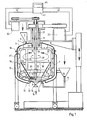
- (1) denotes a vacuum container, the upper opening of which can be closed by means of flanges (2) by a cover (3).
- This lid can be raised in a known manner, for example by one or more hydraulic cylinders or other drive motors, in order to make the interior (4) of the container accessible for cleaning purposes, for example.
- the material to be processed can optionally be filled into a funnel (5) arranged on the lid (3). Its connection to the interior (4) is hermetically sealed by a slide (6) which can be adjusted by means of a crank or similar operating element (7).
- the material can also be sucked in via the funnel (10) and line (11) with shut-off valve (12) through the container bottom (13) under vacuum.
- the finished material is optionally drained by opening an outlet valve (14) which is located centrally in the container axis (19) in the container base (13).
- the vacuum container (1) is connected in a manner not shown to a vacuum pump. It can be provided in the lower cup-shaped container part or in the lid (3).
- the lower part of the container has a double jacket (15) through which the heating and / or cooling medium flows.
- the container can be fixed, movable on a trolley, or tiltable about a horizontal axis. be arranged on a turret body and the like which can be rotated about a preferably vertical axis.
- the homogenizer can be driven by the inner shaft (20), the stirring basket (18) by means of a tubular outer shaft (21). While the inner shaft (20) extends from the upper mixer motor (22), the outer shaft (21) is connected to the lower agitator motor (23) and is mounted in a bearing tube (8) that is flanged onto the cover (3). Both shafts are hermetically sealed through ring seals (24, 25) and passed through the cover (3). Compared to an arrangement of the motors (22, 23) below the tank bottom (13), this facilitates the rotary leadthrough and sealing.
- Both motors (22, 23) and their shafts (20) and (21) can be driven according to arrows (28) and (29) in both directions of rotation with variable speed, preferably using frequency converters.
- the stator (30) of the toothed colloid mill (17) is held firmly on the stirring basket (18), while the rotor (31) is connected to the inner shaft (20).
- the effective rotational speed of the toothed colloid mill thus corresponds to the vectorial difference in the rotational speeds of the shafts (20) and (21). They expediently run in opposite directions.
- a guide cone (34) sits on the inner shaft (20) by means of a sleeve (32) and spoke arms (33), just above the tooth colloid mill, which cone extends the shape of the tooth colloid mill, e.g. has a smooth truncated cone with a tip angle of about 60 ° and comes close to the inner surfaces of the mixing bowl (18). While the outer shaft (21) with the mixing bowl has a speed in the range of 20-100 U / min, the inner shaft (20) runs at a rotation speed of approx. 500-3000 U / min. Since all parts rotate around the shaft of the axis (19), a pronounced central vortex is usually established.
- a vortex breaker (35) is led down from the stirring basket (18) at a radial distance and parallel to the container axis (19) into the guide cone (34). In this way, the local axis of rotation is shifted out of the container axis (19) with constant change, which brings a further mixing effect.
- the spoke arms (33), like the vortex breaker (35) and the other rods (26) of the stirring basket (18), are designed as cylindrical tubes, but can also have other suitable shapes.
- the stirring basket (18) also has a plurality of stripping blades (37) lying against the inner wall (36) of the vacuum container (1) and strippers (47) or the like lying against the outer wall surface of the guide cone.
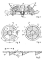
- an axial paddle wheel (46) with an inner ring (54) and an outer ring (55) is used to fasten the rotor (31) of the toothed colloid mill (17), which is arranged in an annular manner by means of star-shaped conveying blades (49) Delivery channel (50) are connected.
- a strong rotational flow is set up centrally to the container axis (19) in the guide cone (34), which serves primarily for mixing, while the smaller quantity of material passed through the pump teeth (56) between the stator and rotor is primarily exposed to the homogenization.
- the material flows mix again and again, so that approximately the same quality of the material can always be achieved in the entire vacuum container.
- a cover member (51) in the form of a cover disk is therefore mounted above the delivery channel (50) in the paddle wheel (46).
- This covering element has three sector wings (57) which form spacing sectors (58) of equal size between them, each with a tip angle of 60 °.
- the conveyor blades (49) have the same sector area, so that the paddle wheel (46) as well as the cover member (51) have the approximate shape of a Maltese has cross. In the open position in FIG.
- the conveying blades (49) are therefore covered by the sector blades (57) in their position (57) from FIG. 5, so that conveying can be carried out through the spacing sectors (58).
- the sectors of the same size join together. This can be designed as required so that the flow is completely or partially blocked.
- a triangular cross section is provided for the conveyor blades (49) according to FIG. 5, but this is unfavorable for flow, in particular if the end face is at the front in the circumferential direction.
- a triangular extension (49 ') can be connected to this end face in the opposite position.
- this cross section can be obtained entirely if a central shutter, as is known in photographic cameras, or a shutter in the manner of a photographic aperture is used.
- the conveying channel (50) can be fully opened, for example when the diaphragm is open.
- the slats are held firmly on the outer stops by centrifugal force.
- the slats In the closed position of the panel, for example. of the lock, the slats must be pressed inwards against the effects of centrifugal force. They are then subjected to greater vibration, so that here the shafts (21, 22) should run in the same direction in order to achieve the lower effective speed of the mill rotor.
- Part of the goods can also be taken continuously or intermittently as a sample and checked for its nature, such as viscosity, grain size, temperature and the like.
- Detectors can also be embedded in the rotatable container (1).
Landscapes
- Chemical & Material Sciences (AREA)
- Chemical Kinetics & Catalysis (AREA)
- Mixers Of The Rotary Stirring Type (AREA)
- Crushing And Grinding (AREA)
Abstract
Description
- Die Erfindung betrifft eine Vorrichtung zum Mischen und Homogenisieren von fliessfähigen Produkten, insbesondere für die pharmazeutische, kosmetische und Lebensmittelindustrie, mit einem durch einen Deckel verschließbaren Vakuumbehälter, einer unten in diesem angeordneten Homogenisiereinrichtung und einer am Deckel angeordneten Misch- bzw. Rühreinrichtung.
- Eine Vorrichtung dieser Art ist bekannt, durch die deutsche Offenlegungsschrift 15 07 528. Dort ist einmal ein Rührwerk mit dicht an der Behälterwandung hochragenden Rührarmen von einem unter dem Behälterboden hängenden Antriebsmotor und ein vom Deckel herabgeführtes Mischwerk von einem eben angeordneten Motor angetrieben. Die als Homogenisiereinrichtung eingesetzte Zahnkolloidmühle ist exzentrisch hängend am Behälterboden angeordnet und fördert das Gut konituierlich durch eine Umlaufleitung zur Entgasung auf einen unter den Deckel angeordneten Schleuderteller, der das Gut durch Fliehkraft ausbreitet und es dann durch ein Ringsieb hindurchschleudert. Auf diese Weise können neben den schon erwähnten Behandlungsvorgängen auch Emulgieren, Dispergieren und Benetzen im gleichen Gerät durchgeführt werden.
- Diese ältere Bauart hat jedoch auch einige Nachteile. Einmal ist die Bauart als solche zu aufwendig, die Umlaufleitung kann verstopfen oder auch die Gleichförmigkeit der Strömung behindern, und das Gut wird durch diesen Umlauf in mancherlei Weise beansprucht, insbesondere erwärmt und erfährt mitunter wenigstens momentan eine Qualitätsveränderung.
- Ferner ist dann durch die DE-PS 24 45 287 eine Vorrichtung zum Mischen und/oder Entgasen von hochviskosen Medien unter Vakuum bekannt, wobei in einem kegelförmigen oder zylindrischen Vakuumbehälter ein ebenso geformtes Rohr umläuft, an dessen Außenseite eine Förderwendel angeformt ist. Dabei wird die verarbeitete Masse zwischen Innenwandung des Behälters und Außenfläche des umlaufenden Rohres mittels einer Schleppströmung zu einem Überlauf hochgefördert, von wo sie wieder zurück in den Stoffspiegel fließt. Dort geht es vor allem um eine möglichst vollständige Entgasung des hochviskosen Gutes und zwar soll der Rotor mit veränderlicher Drehzahl antreibbar sein. Dafür reicht eine geringe Drehzahl aus, die dort auch bevorzugt wird. Mit hohen Drehzahlen läßt sich ohnehin der Rotor kaum betreiben, da die ganze Hochförderung durch die Schneckenwendel bewirkt wird, was leicht zu einer Überwärmung und daher zu einer unerwünschten Änderung der Gutqualität führen kann.
- Die Erfindung geht aus von der eingangs definierten Vorrichtung zum Mischen und Homogenisieren von fliessfähigen Produkten und verfolgt die Aufgabe die bekannte Misch- und Homogenisiervorrichtung auf möglichst einfache Weise derart zu verändern, daß das Gut möglichst ohne Stockung gleich mäßige Beanspruchung erfährt.
- Ausgehend von der eingangs definierten Gattung ist die erfindungsgemäße Vorrichtung dadurch gekennzeichnet, daß die Homogenisiereinrichtung mit lotrechtem Absaug-Abstand über dem Behälterboden angeordnet und im unteren Teil des Vakuumbehälters ein rotierbarer hohler Leitkonus vorgesehen ist.
- Auf diese Weise kann die Homogenisiereinrichtung das Gut unmittelbar seitlich vom Behälterboden absaugen und in den sich nach oben erweiternden Leitkonus hineinfördern. Dabei wird das Gut entlang der konisch erweiterten Innenfläche des Leitkonus nach oben/aussen bis zu dessen Oberkante in den Strömungsringspalt gefördert, den dieser mit der Behälterwandung bildet. Sas Gut breitet sich dabei unter ständiger Schichtverdünnung weitgehend gleichmäßig aus und fliesst in dünnem Ringstrom von der Konus-Oberkante zum Behälterboden.
- Dabei erfolgt zwar auch eine recht weitgehende Entgasung des Gutes; wesentlich ist aber, daß die Wandung des Leitkonus nicht oder kaum mit ausgeprägten Förderschaufeln besetzt sein muß, der Leitkonus also den von der Homogenisiereinrichtung ausgeübten Förderffekt nur an seiner Wandung zu unterstützen braucht und dabei seine Leitfunktion zur Ausbreitung des Gutes auf den Behälterquerschnitt entfalten kann. Dadurch sind wesentlich höhere Drehgeschwindigkeiten zulässig als bei einer auf der ganzen Außenfläche angeordneten Förderwendel. Das Gut wird auch vom Leitkonus nur geringfügig in Umdrehung versetzt, so daß sich an der Wandung des Leitkonus große Geschwindigkeitsdifferenzen ergeben, die hohe Scherkräfte zur Folge haben und damit eine weitergehende Zerkleinerung und Homogenisierung des Gutes bewirken.
- Da der Vakuumbehälter während der Bearbeitung ständig an einer Vakuumpumpe angeschlossen bleibt, wird von Umlauf zu Umlauf der Gasanteil des Gutes verringert. Dieser Anteil kann ebenso wie der Homogenisierungsgrad oder die anderen angestrebten Eigenschaften des Gutes selbstätig gemessen und gegebenenfalls das Verfahren beendet werden, wenn im Hinblick auf eine Reihe vorgegebener Meßwerte Mindestqualifikationen erfüllt sind.
- Enge Stömungsquerschnitte ergeben sich dabei höchstens in der als Umlaufpumpe wirkenden Homogenisiereinrichtung. Es besteht daher weder die Gefahr irgendeiner Verstopfung noch einer Überbeanspruchung oder Qualitätsänderung des Gutes, das sich sehr weitgehend und gleichmäßig entspannen kann. Dabei trägt auch der Leitkonus selbst durch die Dünnschichtströmung auf seiner Oberfläche zum Homogenisieren und ferner zum Dispergieren durch Schwerkraftwirkung des Gutes bei. Er übernimmt auch eine begrenzte Funktion für die Mischung der Gutbestanteile.
- Nach einer bevorzugten Ausführungsform der Erfindung werden Homogenisier- und Misch- bsw. Rühreinrichtung durch zwei in der Behälterachse zentrisch angeordnete Antriebswellen angetrieben, wobei die innere Antriebswelle wenigstens mit der Homogenisiereinrichtung in Verbindung ist, während die äußere Antriebswelle an einen käfigartigen Rührkorb angeschlossen ist. Zweckmäßigerweise sind die Antriebe am Behälterdeckel angeordnet. Das Letztere ermöglicht bessere Übersicht und Abdichtung sowie leichtere Wartung. Im übrigen wird die Zuordnung der verschiedenen Aggregate vereinfacht. Zudem läßt sich so der Leitkonus mit dem Rotor der homogenisiereinrichtung verbinden, indem er etwa durch einen Speichenstern an der inneren Antriebswelle befestigt wird.
- Die Oberfläche des Leitkonus kann exakt geometrisch glattflächig, aber auch strukturiert, vorzugsweise in Umfangsrichtung insbesondere unter gleichen Teilungsabständen radial verändert sein, etwa wellenförmig, kegel- schraubenförmig oder aus der Mantellinie heraus gewölbt.
- Der Stator der Homogenisiereinrichtung läßt sich an den sich an die Behälterwandung anschmiegenden Armen des Rührkorbes anbringen. Drehrichtung und Drehgeschwindigkeit der Homogenisiervorrichtung werden daher durch die Differenz- oder Summe der Geschwindigkeiten der beiden Antriebswellen vorgegeben. Dies begünstigt den Einsatz einer auf Reversierbetrieb eingerichteten Zahnkolloidmühle, die sich wegen ihres geringen Gewichtes und ihrer kleinen Abmessungen auch bei höheren Drehzahlen zuverlässig halten und führen läßt, ohne daß ihre Feinzerkleinerungs- und Emulgierfunktion beeinträchtigt wird.
- Die Umwälzleistung der Homogenisiervorrichtung bzw. der Zahnkolloidmühle kann wesentlich gesteigert werden, wenn gemäß einer Weiterbildung der Erfindung der Mühlenrotor ein insbesondere zu seiner Befestigung an der Innenwelle dienendes Axilalschraubenrad mit durch Abstandssektoren voneinander getrennten Förderschaufeln in einem ringförmigen Förderkanal aufweist bsw. bildet. Auf diese Weise lassen sich zwei gleichsinnig rotierende Strömungen einsetzen, einmal die vom ohnehin vorhandenen Ausgang der Zahnkolloidmühle ausgehende dicht an der Innenwandung des Leitkonus geführte Aussenströmung und zum andern eine die Innenwelle im Leitkonus umschliessende Innenströmung.
- Bei bestimmten Betriebszuständen kann es zweckmäßig sein, die Innenströmung zu drosseln oder abzusperren, was sich durch ein am Axialschaufelrad angeordnetes Abdeckorgan bewerkstelligen läßt, das zwischen Anschlägen um den Umfangswinkel eines Abstandssektors verschwenkbar ist. Dies kann willkürlich geschehen, erfolgt aber vorzugsweise selbsttätig durch das gegenüber dem Rotor zurückbleibende Fördermedium, insbesondere bei Drehzahlumkehr des Rotors.
- Auf diese Weise läßt sich sicherstellen, daß die Innenströmung nur gleichsinnig zum normalen Auslaß der Zahnkolloidmühle verläuft, nicht also das Gut nur um den Rand des Pumpenrotors umgewälzt wird.
- Um die beim Mühlenbetrieb mit ausschließlich um eine gemeinsame Achse drehbaren Teilen leicht auftretende Wirbelbildung zu brechen und die Strömung zu beruhigen, kann von oben etwa axial mit radialem Abstand von der Behälterachse freitragend ein Wirbelbrecher in den Leitkonus vorragen. Dieser am langsam laufenden Rührkorb angebrachte Arm wirkt dabei vor allem der von der schnell laufenden Homogenisiervorrichtung herrührenden Verwirbelung entgegen.
- Homogenisiereinrichtung und Rührwerk werden vorzugsweise an unterschiedliche Antriebsmotoren angeschlossen, von welchen wenigstens einer umkehrbar und mindestens einer, insbesondere beide, drehzahlregelbar ausgebildet ist, bzw. sind. Auf diese Weise lassen sich praktisch alle Abweichungen vom vorprogrammierten Ergebnis der Bearbeitung korrigieren.
- Um dies zu erleichtern, wird bsw. werden zweckmäßigerweise wenigstens ein, insbesondere beide Antriebsmotoren an eine Steuerung zum selbstätigen Steuern der Antriebe nach vorgegebenen oder selbstätig erfaßbaren Betriebsdaten der Vorrichtung und/oder des bearbeiteten Gutes angeschlossen.
- Vorzugsweise ist einem Steuergerät der Vorrichtung ein Vergleichsrechner zugeordnet, der aus allen ihm zugeführten Vorgaben und Funktionswerten Steuerwerte ermittelt und zur Weitergabe an den oder die Antriebsmotoren vorbereitet.
- Weitere Ausgestaltungen und Vorteile der Erfindung sind in den Unteransprüchen definiert und sollen nun anhand der schematischen Darstellung einer erfindungsgemäßen Vorrichtung zum Mischen und Homogenisieren von fliessfähigen Pro dukten beschrieben werden. Es zeigen
- Fig. 1 eine schematische Übersichtsdarstellung dieser Vorrichtung mit Schaltbild,
- Fig. 2 einen vergrößerten Teilschnitt einer Zahnkolloidmühle der Homogenisiervorrichtung,
- Fig. 3 eine Ansicht auf ein in der Zahnkolloidmühle fest angebrachtes Schaufelrad in der Öffnungsstellung einer Abdeckvorrichtung,
- Fig. 4 die Darstellung aus Fig. 3 mit geschlossener Abdeckvorrichtung und
- Fig. 5 einen Umfangsschnitt durch das Schaufelrad nach der Linie V-V in Fig. 4.
- In der Zeichnung ist mit (1) ein Vakuumbehälter bezeichnet, dessen obere Öffnung mittels Flansche (2) durch einen Deckel (3) verschließbar ist. Dieser Deckel kann in bekannter Weise etwa durch einen oder mehrere Hydraulikzylinder oder andere Antriebsmotoren in gebotener Weise angehoben werden, um den Innenraum (4) des Behälters etwa für Reinigungszwecke zugängig zu machen.
- Das zu verarbeitende Gut kann wahlweise in einen am Deckel (3) angeordneten Trichter (5) eingefüllt werden. Dessen Verbindung mit dem Innenraum (4) ist hermetisch durch einen Schieber (6) abgeschlossen, der durch eine Kurbel oder dergleichen Bedienungselement (7) zu verstellen ist.
- Man kann das Gut aber auch über den Trichter (10) und Leitung (11) mit Absperrventil (12) durch den Behälterboden (13) unter Vakuum einsaugen. Das fertig bearbeitete Gut wird gegebenenfalls durch Öffnen eines Auslaßventils (14) abgelassen, das zentrisch in der Behälterachse (19) im Behälterboden (13) sitzt.
- Der Vakuumbehälter (1) ist in nicht weiter gezeigter Weise an eine Vakuumpumpe angeschlossen. Er kann im unteren becherförmigen Behälterteil oder im Deckel (3) vorgesehen sein. Der untere Behälterteil besitzt einen Doppelmantel (15), der vom Heiz- und/oder Kühlmedium durchgeströmt ist. Beispielsweise kann der Behälter fest, verfahrbar auf einem Wagen, um eine waagerechte Achse kippbar bsw. an einem um eine vorzugsweise lotrechte Achse drehbaren Revolverkörper und dergleichen angeordnet sein.
- Eine Homogenisiereinrichtung (16), die vorzugsweise eine Zahnkolloidmühle (17) aufweist, und ein Rührkorb (18) sind in der lotrechten Behälterachse (19) drehbar gelagert. Die Homogenisiereinrichtung ist von der Innenwelle (20), der Rührkorb (18) mittels einer rohrförmigen Außenwelle (21) antreibbar. Während die Innenwelle (20) vom oberen Mischmotor (22) ausgeht, ist die Außenwelle (21) an den unteren Rührmotor (23) angeschlossen und in einem fest auf dem Deckel (3) aufgeflanschten Lagerrohr (8) gelagert. Beide Wellen sind durch Ringdichtungen (24, 25) hermetisch abgeschlossen durch den Deckel (3) hindurchgeführt. Dies erleichtert gegenüber einer Anordnung der Motoren (22, 23) unterhalb des Behälterbodens (13), die Drehdurchführung und Abdichtung.
- Beide Motoren (22, 23) und ihre Wellen (20) und (21) sind gemäß den Pfeilen (28) und (29) in beiden Drehrichtungen mit veränderlicher Drehzahl antreibbar, vorzugsweise unter Einsatz von Frequenzumformern.
- Der Stator (30) der Zahnkolloidmühle (17) ist fest am Rührkorb (18) gehalten, während der Rotor (31) an die Innenwelle (20) angeschlossen ist, Damit entspricht die effektive Drehgeschwindigkeit der Zahnkolloidmühle der vektoriellen Differenz der Drehgeschwindigkeiten der Wellen (20) und (21). Sie laufen zweckmäßigerweise gegensinnig um.
- Auf der Innenwelle (20) sitzt mittels Muffe (32) und Speichenarmen (33) dicht über der Zahnkolloidmühle ein Leitkonus (34), der die Form eines etwa von der Oberseite der Zahnkolloidmühle bis zur Behältermitte erweiterten z.B. glattflächigen Kegelstumpfes mit einem Spitzenwinkel von etwa 60° hat und dicht an die Innenflächen des Rührkorbes (18) heranreicht. Während die Außenwelle (21) mit dem Rührkorb eine Drehzahl im Bereich von 20-100 U/min hat, läuft die Innenwelle (20) mit einer Drehgeschwindigkeit von ca. 500-3000 U/min. Da alle Teile um die Welle der Achse (19) rotieren, stellt sich normalerweise ein ausgeprägter Zentralwirbel ein. Um dem entgegenzuwirken, ist vom Rührkorb (18) mit radialem Abstand und parallel zur Behälterachse (19) ein Wirbelbrecher (35) bis in den Leitkonus (34) herabgeführt. Auf diese Weise wird die örtliche Rotationsachse unter ständiger Veränderung aus der Behälterachse (19) heraus verlagert, was einen weiteren Mischeffekt bringt.
- Die Speichenarme (33) sind ebenso wie der Wirbelbrecher (35) und die übrigen Stäbe (26) des Rührkorbes (18) als zylindrische Rohre ausgebildet, können aber auch andere geeignete Formen haben. Der Rührkorb (18) trägt zudem am Umfang verteilt, eine Mehrzahl an der Innenwandung (36) des Vakuumbehälters (1) anliegende Abstreifblätter (37) und an der Außenwandfläche des Leitkonus anliegende Abstreifer (47) oder dergleichen.
- Aus der Zeichnung ist ohne weiteres erkennbar, daß im Vakuumbehälter eine ständige Dünnschichtzirkulation des behandelten Gutes erfolgt. Das Gut wird von der Zahnkolloidmühle (17) beim normalen Betrieb vom Behälterboden (13) aufgenommen, zerkleinert, homogenisiert und in den Innenraum des Leitkonus (34) hochgefördert, wo es unter Zentrifugalwirkung an dessen Innenwandung hochläuft und nach schräg oben/außen geschleudert wird. Besonders große Scherkräfte stellen sich an der Anlagefläche des Gutes am Leitkonus (34) ein. Dabei bildet sich im unteren Teil ein etwa hyperbolischer Flüssigkeitsspiegel, wobei zur Oberkante (38) des Leitkonus hin die Dicke der Gutschicht immer kleiner wird, bis das Gut zur Innenwandung (36) nach außen geschleudert wird bzw. von der Oberkante (38) auf den Behälterboden (13) herabläuft. Wenn nach einer Reihe von Bearbeitungszyklen der angestrebte Endzustand erreicht ist, wird das fertige Gut abgelassen.
- Wie am besten aus Fig. 2 zu ersehen, dient zur Befestigung des Rotors (31) der Zahnkolloidmühle (17) ein Axialschaufelrad (46) mit Innenring (54) und Außenring (55), die durch sternförmig angeordnete Förderschaufeln (49) in einem ringförmigen Förderkanal (50) verbunden sind. Auf diese Weise wird zentrisch zur Behälterachse (19) im Leitkonus (34) eine kräftige Rotationsströmung aufgebaut, die vor allem dem Durchmischen dient, während die von den Pumpenzähnen (56) zwischen Stator und Rotor hindurchgeführte geringere Gutmenge vornehmlich der Homogenisation ausgesetzt wird. Beim Rücklauf zum Behälterboden mischen sich die Gutströme immer wieder, so daß im gesamten Vakuumbehälter stets etwa gleiche Gutbeschaffenheit erreicht werden kann.
- Während jedoch die Außenströmung von der Drehrichtung des Rotors (31) unabhängig ist, wird die Strömungsrichtung im Förderkanal (50) bei Änderung der Drehrichtung umgekehrt. Um gegensinnige Strömungen weitgehend zu vermeiden oder wenigstens zu mindern, ist daher oberhalb des Förderkanals (50) im Schaufelrad (46) ein Abdeckorgan (51) in Form einer Abdeckscheibe gelagert. Dieses Abdeckorgan weist drei Sektorenflügel (57) auf, die zwischen sich gleich große Abstandssektoren (58) mit jeweils einem Spitzenwinkel von 60° bilden. Auch die Förderschaufeln (49) haben die gleiche Sektorfläche, so daß das Schaufelrad (46) ebenso wie das Abdeckorgan (51) die angenäherte Form eines Malteser kreuzes hat. Bei der Öffnungsstellung in Fig. 3 sind daher die Förderschaufeln (49) durch die Sektorenflügel (57) in deren Stellung (57) aus Fig. 5 überdeckt, so daß durch die Abstandssektoren (58) hindurch gefördert werden kann. Dagegen fügen sich bei der Schließstellung nach Fig. 4 die gleich großen Sektoren aneinander an. Dies kann nach Bedarf so gestaltet werden, daß der Durchfluß ganz oder teilweise gesperrt ist.
- Um eine völlige Sperrung zu erreichen, ist nach Fig. 5 ein Dreieck-Querschnitt für die Förderschaufeln (49) vorgesehen, der jedoch strömungsungünstig ist, insbesondere, wenn die Stirnfläche in der Umlaufrichtung vorn liegt. Zur Verbesserung der Stömungsform läßt sich an dieser Stirnfläche in umgekehrter Lage ein dreieckförmiger Ansatz (49′) anschliessen.
- Der Abschluß kann einmal mit strömungsgünstigen dünnen Förderschaufeln (49) verbessert werden, wenn man zwei Abdeckorgane (51) übereinander anordnet, wovon das eine fest mit dem Pumpenrad bzw. dem Pumpenrotor verbunden ist, während das andere in einer ersten Drehrichtung unter dem festen Abdeckorgan bleibt, durch Drehzahlumkehr aber ganz unter diesem herausgeschwenkt wird. Auf diese Weise können auch eine Mehrzahl sektorförmige Lamellen übereinander angeordnet sein und um die Behälterachse (19) nacheinander ausgeschwenkt werden. Auch dabei wird jedoch der Durchflußquerschnitt des Förderkanals (50) eingeschränkt.
- Dieser Querschnitt kann jedoch ganz erhalten werden, wenn man einen Zentralverschluß einsetzt, wie er bei fotografischen Kameras bekannt ist, oder einer Verschluß nach Art einer fotografischen Blende. Beispielsweise kann man jeweils zwei Blendenelemente von entgegengesetzten Seiten zur Mitte hinschwenken, so daß man für vier Abdeckelemente insgesamt nur zwei Lagen von der Dicke einer Lamelle benötigt. Auf diese Weise kann etwa bei geöffneter Blende der Förderkanal (50) voll geöffnet werden. Um jedoch mögliche Vibrationen zu mindern, empfiehlt es sich, im normalen Förderbetrieb mit gegesinniger Drehrichtung der Wellen (20, 21) und damit größter vektorieller Geschwindigkeitsdifferenz bzw. Effektivdrehzahl des Rotors (31) gegenüber dem Stator (30) arbeiten zu können. Dabei sind die Lamellen unter Fliehkraftwirkung fest an äusseren Anschlägen gehalten.
- In der Schließstellung der Blende bsw. des Verschlusses müssen die Lamellen gegen Fliehkraftwirkung nach innen gedrückt werden. Sie werden dann stärkerer Erschütterung ausgesetzt, so daß hier die Wellen (21, 22) gleichsinnig laufen sollten, um die kleinere effektive Drehzahl des Mühlenrotors zu erreichen.
- Dabei kann auch ein Teil des Gutes ständig oder intermittierend als Probe entnommen und auf seine Beschaffenheit, wie Viskosität, Korngröße, Temperatur und dergleichen überprüft werden. Es können auch Detektoren in den drehbar gehaltenen Behälter (1) eingelassen sein.
- Auf diese Weise ist es möglich, bestimmte Betriebswerte, insbesondere die Motorstromaufnahme, vorzuwählen, wobei sich etwa bei einer Einstellung von 20 Amp. eine Drehzahl von etwa 800 U/min. bei einer Viskosität von 5000 cp einstellt. Fällt die Viskosität durch Bearbeitung und Benetzung der Trockenprodukte auf etwa 1000 cp herab, so erhöht sich die Drehzahl auf ca. 1300 U/min., bis wieder die voreingestellten 20 Amp. erreicht sind. Dabei kann diese Stromaufnahme wahlweise für einen der beiden Einzelmotoren oder für beide Motoren vorgegeben werden. Es kann auch ein Verhältnis der Stromaufnahmen wie überhaupt Verhältnisse unterschiedlicher Betriebswerte vorgegeben und im Weiterverlauf konstant gehalten werden. Vor allem läßt sich exakt vorgeben, welche energie in der Zeiteinheit eingesetzt werden soll. Diese Vorgabewerte können auch laufend nebst anderen Betriebswerten selbsttätig angepaßt werden.
Claims (19)
Priority Applications (1)
| Application Number | Priority Date | Filing Date | Title |
|---|---|---|---|
| AT89102854T ATE104170T1 (de) | 1988-03-29 | 1989-02-18 | Vorrichtung zum mischen und homogenisieren von fliessfaehigen produkten. |
Applications Claiming Priority (2)
| Application Number | Priority Date | Filing Date | Title |
|---|---|---|---|
| DE3810609A DE3810609A1 (de) | 1988-03-29 | 1988-03-29 | Vorrichtung zum mischen und homogenisieren von fliessfaehigen produkten |
| DE3810609 | 1988-03-29 |
Publications (3)
| Publication Number | Publication Date |
|---|---|
| EP0335096A2 true EP0335096A2 (de) | 1989-10-04 |
| EP0335096A3 EP0335096A3 (de) | 1992-03-11 |
| EP0335096B1 EP0335096B1 (de) | 1994-04-13 |
Family
ID=6350944
Family Applications (1)
| Application Number | Title | Priority Date | Filing Date |
|---|---|---|---|
| EP89102854A Expired - Lifetime EP0335096B1 (de) | 1988-03-29 | 1989-02-18 | Vorrichtung zum Mischen und Homogenisieren von fliessfähigen Produkten |
Country Status (4)
| Country | Link |
|---|---|
| EP (1) | EP0335096B1 (de) |
| AT (1) | ATE104170T1 (de) |
| DE (2) | DE3810609A1 (de) |
| ES (1) | ES2050727T3 (de) |
Cited By (12)
| Publication number | Priority date | Publication date | Assignee | Title |
|---|---|---|---|---|
| EP1186340A1 (de) * | 2000-07-31 | 2002-03-13 | Dow Corning Toray Silicone Co., Ltd. | Kontinuierlich arbeitender Mischer |
| EP1125625B1 (de) * | 2000-02-18 | 2007-04-18 | symex GmbH & Co. KG | Homogenisiereinrichtung |
| EP1862215A1 (de) * | 2006-05-31 | 2007-12-05 | Michel Albert | Vorrichtung zur Herstellung und vorübergehenden Aufbewahrung von flüssigem Hefeteig |
| WO2012098329A1 (fr) | 2011-01-21 | 2012-07-26 | Boccard | Dispositif, installation et procede pour melanger des substances sous forme liquide et/ou pulverulente |
| US20140330055A1 (en) * | 2011-09-19 | 2014-11-06 | Korea Institute Of Industrial Technology | Method and apparatus for improving heat transfer and reaction efficiency of gas hydrate reactor using scraper |
| CN111318196A (zh) * | 2020-03-28 | 2020-06-23 | 江苏国胶新材料有限公司 | 一种聚羧酸母液制备用复配装置 |
| CN111701515A (zh) * | 2020-07-01 | 2020-09-25 | 苏州新派特信息科技有限公司 | 一种化妆品生产用粉底液原料混合设备 |
| CN111905587A (zh) * | 2019-05-09 | 2020-11-10 | 艾力集团有限责任公司-卡皮贾尼 | 搅拌单元、包括该搅拌单元的机器和制作液态或半液态食品的方法 |
| CN112660626A (zh) * | 2020-12-14 | 2021-04-16 | 江西长通实业有限公司 | 一种抑菌凝胶生产用的储料输料结构 |
| US11033865B2 (en) * | 2017-01-03 | 2021-06-15 | Lg Chem, Ltd. | Dissolution mixer |
| EP4223134A1 (de) * | 2022-02-01 | 2023-08-09 | Kälte-Rudi GmbH & Co. KG | Vorrichtung zur herstellung eines fliessfähigen produktes |
| CN117427546A (zh) * | 2023-12-21 | 2024-01-23 | 华南农业大学 | 一种物料搅拌装置、混料加料设备及混料加料方法 |
Families Citing this family (4)
| Publication number | Priority date | Publication date | Assignee | Title |
|---|---|---|---|---|
| DE19629945C5 (de) * | 1996-07-25 | 2008-10-16 | Ika-Werke Gmbh & Co. Kg | Mischvorrichtung zum Vermischen von pulverförmigen und/oder körnigen Partikeln mit einer Flüssigkeit |
| DE10316730A1 (de) * | 2003-04-07 | 2004-10-28 | Freie Universität Berlin | Vakuum-Drehdurchführung |
| IT1399085B1 (it) * | 2010-03-25 | 2013-04-05 | G S G Srl | Macchina per il tattamento di miscele alimentari a rendimento migliorato. |
| CN113893739A (zh) * | 2021-11-11 | 2022-01-07 | 方梦丹 | 一种水系灭火剂制备用添加剂定量投放旋转混合装置 |
Family Cites Families (9)
| Publication number | Priority date | Publication date | Assignee | Title |
|---|---|---|---|---|
| CH228208A (de) * | 1941-12-18 | 1943-08-15 | Sulzer Ag | Rührwerk in Gefässen, insbesondere in Autoklaven. |
| FR1315140A (fr) * | 1961-12-06 | 1963-01-18 | Perfectionnements aux agitateurs | |
| DE1457141A1 (de) * | 1964-10-10 | 1968-12-19 | Gustav Spangenberg Gmbh Maschi | Misch- und Dispergiermaschine |
| DE1262235B (de) * | 1965-06-17 | 1968-03-07 | Brogli & Co | Kombinierte Misch- und Homogenisiermaschine |
| DE1507528B1 (de) * | 1966-12-06 | 1970-09-24 | Fryma Masch Ag | Vorrichtung zum Verarbeiten und Aufbereiten fliessfaehiger Produkte |
| US3826435A (en) * | 1972-02-12 | 1974-07-30 | Oliver And Batlle Sa | Apparatus for dispersing pigments in a liquid phase |
| DE2445287C3 (de) * | 1974-09-21 | 1984-09-20 | Arthur Pfeiffer Vakuumtechnik Wetzlar Gmbh, 6334 Asslar | Vorrichtung zum Mischen und/oder Entgasen von hochviskosen Medien unter Vakuum |
| DE3026493A1 (de) * | 1980-07-12 | 1982-02-04 | Wilhelm Hedrich Vakuumanlagen GmbH und Co KG, 6332 Ehringshausen | Vorrichtung zum mischen und entgasen von komponenten von kunstharzen, insbesondere von duroplastischen kunstharzen |
| DE3218637A1 (de) * | 1982-05-18 | 1983-11-24 | Haagen & Rinau | Mischvorrichtung |
-
1988
- 1988-03-29 DE DE3810609A patent/DE3810609A1/de not_active Withdrawn
-
1989
- 1989-02-18 EP EP89102854A patent/EP0335096B1/de not_active Expired - Lifetime
- 1989-02-18 ES ES89102854T patent/ES2050727T3/es not_active Expired - Lifetime
- 1989-02-18 AT AT89102854T patent/ATE104170T1/de not_active IP Right Cessation
- 1989-02-18 DE DE58907425T patent/DE58907425D1/de not_active Expired - Fee Related
Cited By (18)
| Publication number | Priority date | Publication date | Assignee | Title |
|---|---|---|---|---|
| EP1125625B1 (de) * | 2000-02-18 | 2007-04-18 | symex GmbH & Co. KG | Homogenisiereinrichtung |
| EP1825907A1 (de) * | 2000-02-18 | 2007-08-29 | symex GmbH & Co. KG | Homogenisator ("Co-Twister") |
| EP1186340A1 (de) * | 2000-07-31 | 2002-03-13 | Dow Corning Toray Silicone Co., Ltd. | Kontinuierlich arbeitender Mischer |
| EP1862215A1 (de) * | 2006-05-31 | 2007-12-05 | Michel Albert | Vorrichtung zur Herstellung und vorübergehenden Aufbewahrung von flüssigem Hefeteig |
| FR2901664A1 (fr) * | 2006-05-31 | 2007-12-07 | Michel Albert | Dispositif d'elaboration et stockage temporaire de levain liquide |
| WO2012098329A1 (fr) | 2011-01-21 | 2012-07-26 | Boccard | Dispositif, installation et procede pour melanger des substances sous forme liquide et/ou pulverulente |
| US20140330055A1 (en) * | 2011-09-19 | 2014-11-06 | Korea Institute Of Industrial Technology | Method and apparatus for improving heat transfer and reaction efficiency of gas hydrate reactor using scraper |
| US10023821B2 (en) * | 2011-09-19 | 2018-07-17 | Korea Institute Of Industrial Technology | Method and apparatus for improving heat transfer and reaction efficiency of gas hydrate reactor using scraper |
| US11033865B2 (en) * | 2017-01-03 | 2021-06-15 | Lg Chem, Ltd. | Dissolution mixer |
| US11617377B2 (en) * | 2019-05-09 | 2023-04-04 | Ali Group S.R.L.—Carpigiani | Stirring unit, machine comprising the stirring unit and method for making liquid or semi-liquid food products |
| CN111905587A (zh) * | 2019-05-09 | 2020-11-10 | 艾力集团有限责任公司-卡皮贾尼 | 搅拌单元、包括该搅拌单元的机器和制作液态或半液态食品的方法 |
| US20200352193A1 (en) * | 2019-05-09 | 2020-11-12 | Ali Group S.R.L. - Carpigiani | Stirring unit, machine comprising the stirring unit and method for making liquid or semi-liquid food products |
| CN111318196A (zh) * | 2020-03-28 | 2020-06-23 | 江苏国胶新材料有限公司 | 一种聚羧酸母液制备用复配装置 |
| CN111701515A (zh) * | 2020-07-01 | 2020-09-25 | 苏州新派特信息科技有限公司 | 一种化妆品生产用粉底液原料混合设备 |
| CN112660626A (zh) * | 2020-12-14 | 2021-04-16 | 江西长通实业有限公司 | 一种抑菌凝胶生产用的储料输料结构 |
| EP4223134A1 (de) * | 2022-02-01 | 2023-08-09 | Kälte-Rudi GmbH & Co. KG | Vorrichtung zur herstellung eines fliessfähigen produktes |
| CN117427546A (zh) * | 2023-12-21 | 2024-01-23 | 华南农业大学 | 一种物料搅拌装置、混料加料设备及混料加料方法 |
| CN117427546B (zh) * | 2023-12-21 | 2024-03-12 | 华南农业大学 | 一种物料搅拌装置、混料加料设备及混料加料方法 |
Also Published As
| Publication number | Publication date |
|---|---|
| EP0335096A3 (de) | 1992-03-11 |
| DE3810609A1 (de) | 1989-10-12 |
| EP0335096B1 (de) | 1994-04-13 |
| ATE104170T1 (de) | 1994-04-15 |
| DE58907425D1 (de) | 1994-05-19 |
| ES2050727T3 (es) | 1994-06-01 |
Similar Documents
| Publication | Publication Date | Title |
|---|---|---|
| EP0335096B1 (de) | Vorrichtung zum Mischen und Homogenisieren von fliessfähigen Produkten | |
| EP1943022B1 (de) | Rührwerksmühle | |
| DE3784127T2 (de) | Vorbehandlungsgeraet fuer eine strangpresse. | |
| EP3202489B1 (de) | Vorrichtung zum homogenisieren und/oder dispergieren fliessfähiger produkte | |
| DE2709309A1 (de) | Vorrichtung zur zufuehrung fliessfaehiger feststoffe | |
| DE69106951T2 (de) | Dispersionsvorrichtung. | |
| DE3617175C2 (de) | Einrichtung zum Passieren, insbesondere Granulieren und/oder Sieben eines Gutes | |
| DE60223675T2 (de) | Homogenisiervorrichtung | |
| EP0439826A1 (de) | Rührwerksmühle | |
| DE6910964U (de) | Mischvorrichtung | |
| DE19537303B4 (de) | Vorrichtung zum Homogenisieren fließfähiger Stoffe | |
| DE19923378A1 (de) | Vorrichtung zum Homogenisieren fließfähiger Stoffe | |
| DE2445287C3 (de) | Vorrichtung zum Mischen und/oder Entgasen von hochviskosen Medien unter Vakuum | |
| DE1913940C2 (de) | Mischvorrichtung | |
| DE3633499C1 (en) | Apparatus for mechanical treatment of mixtures of at least two substances | |
| DE102019128670A1 (de) | Vorratseinheit für flüssiges und viskoses Material sowie Verfahren zum Entgasen des Materials | |
| DE2318949B1 (de) | Kombinierte Misch- und Homogenisiermaschine | |
| DE4419919C1 (de) | Rührwerksmühle | |
| EP3953028B1 (de) | Vorrichtung zur herstellung von granulaten oder extrudaten | |
| EP0728839B1 (de) | Rührwerk-Rührflügelanordnung sowie Rührwerk für ein Maischgefäss | |
| DE2720415A1 (de) | Vorrichtung zum mischen von koernigem material mit einer fluessigkeit | |
| DE1295343B (de) | Stoffloeser fuer Faserstoffe zur Papierherstellung | |
| DE3111124C2 (de) | ||
| DE20221717U1 (de) | Homogenisiergerät | |
| DE2739106C2 (de) | Vorrichtung zum Rühren einer feste Teilchen enthaltenden Flüssigkeit |
Legal Events
| Date | Code | Title | Description |
|---|---|---|---|
| PUAI | Public reference made under article 153(3) epc to a published international application that has entered the european phase |
Free format text: ORIGINAL CODE: 0009012 |
|
| AK | Designated contracting states |
Kind code of ref document: A2 Designated state(s): AT BE CH DE ES FR GB IT LI NL |
|
| PUAL | Search report despatched |
Free format text: ORIGINAL CODE: 0009013 |
|
| AK | Designated contracting states |
Kind code of ref document: A3 Designated state(s): AT BE CH DE ES FR GB IT LI NL |
|
| 17P | Request for examination filed |
Effective date: 19920319 |
|
| 17Q | First examination report despatched |
Effective date: 19920813 |
|
| GRAA | (expected) grant |
Free format text: ORIGINAL CODE: 0009210 |
|
| AK | Designated contracting states |
Kind code of ref document: B1 Designated state(s): AT BE CH DE ES FR GB IT LI NL |
|
| REF | Corresponds to: |
Ref document number: 104170 Country of ref document: AT Date of ref document: 19940415 Kind code of ref document: T |
|
| REF | Corresponds to: |
Ref document number: 58907425 Country of ref document: DE Date of ref document: 19940519 |
|
| REG | Reference to a national code |
Ref country code: ES Ref legal event code: FG2A Ref document number: 2050727 Country of ref document: ES Kind code of ref document: T3 |
|
| GBT | Gb: translation of ep patent filed (gb section 77(6)(a)/1977) |
Effective date: 19940511 |
|
| ITF | It: translation for a ep patent filed | ||
| ET | Fr: translation filed | ||
| PLBE | No opposition filed within time limit |
Free format text: ORIGINAL CODE: 0009261 |
|
| STAA | Information on the status of an ep patent application or granted ep patent |
Free format text: STATUS: NO OPPOSITION FILED WITHIN TIME LIMIT |
|
| 26N | No opposition filed | ||
| PGFP | Annual fee paid to national office [announced via postgrant information from national office to epo] |
Ref country code: AT Payment date: 20011221 Year of fee payment: 14 |
|
| PGFP | Annual fee paid to national office [announced via postgrant information from national office to epo] |
Ref country code: GB Payment date: 20011231 Year of fee payment: 14 |
|
| REG | Reference to a national code |
Ref country code: GB Ref legal event code: IF02 |
|
| PGFP | Annual fee paid to national office [announced via postgrant information from national office to epo] |
Ref country code: BE Payment date: 20020110 Year of fee payment: 14 |
|
| PGFP | Annual fee paid to national office [announced via postgrant information from national office to epo] |
Ref country code: ES Payment date: 20020211 Year of fee payment: 14 |
|
| PGFP | Annual fee paid to national office [announced via postgrant information from national office to epo] |
Ref country code: CH Payment date: 20020214 Year of fee payment: 14 |
|
| PGFP | Annual fee paid to national office [announced via postgrant information from national office to epo] |
Ref country code: FR Payment date: 20020225 Year of fee payment: 14 |
|
| PGFP | Annual fee paid to national office [announced via postgrant information from national office to epo] |
Ref country code: NL Payment date: 20020228 Year of fee payment: 14 |
|
| PGFP | Annual fee paid to national office [announced via postgrant information from national office to epo] |
Ref country code: DE Payment date: 20020424 Year of fee payment: 14 |
|
| PG25 | Lapsed in a contracting state [announced via postgrant information from national office to epo] |
Ref country code: GB Free format text: LAPSE BECAUSE OF NON-PAYMENT OF DUE FEES Effective date: 20030218 Ref country code: AT Free format text: LAPSE BECAUSE OF NON-PAYMENT OF DUE FEES Effective date: 20030218 |
|
| PG25 | Lapsed in a contracting state [announced via postgrant information from national office to epo] |
Ref country code: ES Free format text: LAPSE BECAUSE OF NON-PAYMENT OF DUE FEES Effective date: 20030219 |
|
| PG25 | Lapsed in a contracting state [announced via postgrant information from national office to epo] |
Ref country code: LI Free format text: LAPSE BECAUSE OF NON-PAYMENT OF DUE FEES Effective date: 20030228 Ref country code: CH Free format text: LAPSE BECAUSE OF NON-PAYMENT OF DUE FEES Effective date: 20030228 Ref country code: BE Free format text: LAPSE BECAUSE OF NON-PAYMENT OF DUE FEES Effective date: 20030228 |
|
| PG25 | Lapsed in a contracting state [announced via postgrant information from national office to epo] |
Ref country code: NL Free format text: LAPSE BECAUSE OF NON-PAYMENT OF DUE FEES Effective date: 20030901 |
|
| PG25 | Lapsed in a contracting state [announced via postgrant information from national office to epo] |
Ref country code: DE Free format text: LAPSE BECAUSE OF NON-PAYMENT OF DUE FEES Effective date: 20030902 |
|
| GBPC | Gb: european patent ceased through non-payment of renewal fee | ||
| REG | Reference to a national code |
Ref country code: CH Ref legal event code: PL |
|
| PG25 | Lapsed in a contracting state [announced via postgrant information from national office to epo] |
Ref country code: FR Free format text: LAPSE BECAUSE OF NON-PAYMENT OF DUE FEES Effective date: 20031031 |
|
| NLV4 | Nl: lapsed or anulled due to non-payment of the annual fee |
Effective date: 20030901 |
|
| REG | Reference to a national code |
Ref country code: FR Ref legal event code: ST |
|
| REG | Reference to a national code |
Ref country code: ES Ref legal event code: FD2A Effective date: 20030219 |
|
| PG25 | Lapsed in a contracting state [announced via postgrant information from national office to epo] |
Ref country code: IT Free format text: LAPSE BECAUSE OF NON-PAYMENT OF DUE FEES;WARNING: LAPSES OF ITALIAN PATENTS WITH EFFECTIVE DATE BEFORE 2007 MAY HAVE OCCURRED AT ANY TIME BEFORE 2007. THE CORRECT EFFECTIVE DATE MAY BE DIFFERENT FROM THE ONE RECORDED. Effective date: 20050218 |