EP0335094A2 - Dispositif de calibrage d'un capteur de position - Google Patents
Dispositif de calibrage d'un capteur de position Download PDFInfo
- Publication number
- EP0335094A2 EP0335094A2 EP19890102670 EP89102670A EP0335094A2 EP 0335094 A2 EP0335094 A2 EP 0335094A2 EP 19890102670 EP19890102670 EP 19890102670 EP 89102670 A EP89102670 A EP 89102670A EP 0335094 A2 EP0335094 A2 EP 0335094A2
- Authority
- EP
- European Patent Office
- Prior art keywords
- fuel injection
- displacement sensor
- injection pump
- potentiometer
- operating points
- Prior art date
- Legal status (The legal status is an assumption and is not a legal conclusion. Google has not performed a legal analysis and makes no representation as to the accuracy of the status listed.)
- Granted
Links
Images
Classifications
-
- F—MECHANICAL ENGINEERING; LIGHTING; HEATING; WEAPONS; BLASTING
- F02—COMBUSTION ENGINES; HOT-GAS OR COMBUSTION-PRODUCT ENGINE PLANTS
- F02D—CONTROLLING COMBUSTION ENGINES
- F02D41/00—Electrical control of supply of combustible mixture or its constituents
- F02D41/30—Controlling fuel injection
-
- F—MECHANICAL ENGINEERING; LIGHTING; HEATING; WEAPONS; BLASTING
- F02—COMBUSTION ENGINES; HOT-GAS OR COMBUSTION-PRODUCT ENGINE PLANTS
- F02D—CONTROLLING COMBUSTION ENGINES
- F02D41/00—Electrical control of supply of combustible mixture or its constituents
- F02D41/24—Electrical control of supply of combustible mixture or its constituents characterised by the use of digital means
- F02D41/26—Electrical control of supply of combustible mixture or its constituents characterised by the use of digital means using computer, e.g. microprocessor
- F02D41/28—Interface circuits
-
- F—MECHANICAL ENGINEERING; LIGHTING; HEATING; WEAPONS; BLASTING
- F02—COMBUSTION ENGINES; HOT-GAS OR COMBUSTION-PRODUCT ENGINE PLANTS
- F02D—CONTROLLING COMBUSTION ENGINES
- F02D41/00—Electrical control of supply of combustible mixture or its constituents
- F02D41/30—Controlling fuel injection
- F02D41/38—Controlling fuel injection of the high pressure type
- F02D41/40—Controlling fuel injection of the high pressure type with means for controlling injection timing or duration
- F02D41/406—Electrically controlling a diesel injection pump
-
- F—MECHANICAL ENGINEERING; LIGHTING; HEATING; WEAPONS; BLASTING
- F02—COMBUSTION ENGINES; HOT-GAS OR COMBUSTION-PRODUCT ENGINE PLANTS
- F02D—CONTROLLING COMBUSTION ENGINES
- F02D2200/00—Input parameters for engine control
- F02D2200/02—Input parameters for engine control the parameters being related to the engine
- F02D2200/04—Engine intake system parameters
- F02D2200/0404—Throttle position
-
- F—MECHANICAL ENGINEERING; LIGHTING; HEATING; WEAPONS; BLASTING
- F02—COMBUSTION ENGINES; HOT-GAS OR COMBUSTION-PRODUCT ENGINE PLANTS
- F02D—CONTROLLING COMBUSTION ENGINES
- F02D2250/00—Engine control related to specific problems or objectives
- F02D2250/16—End position calibration, i.e. calculation or measurement of actuator end positions, e.g. for throttle or its driving actuator
-
- Y—GENERAL TAGGING OF NEW TECHNOLOGICAL DEVELOPMENTS; GENERAL TAGGING OF CROSS-SECTIONAL TECHNOLOGIES SPANNING OVER SEVERAL SECTIONS OF THE IPC; TECHNICAL SUBJECTS COVERED BY FORMER USPC CROSS-REFERENCE ART COLLECTIONS [XRACs] AND DIGESTS
- Y02—TECHNOLOGIES OR APPLICATIONS FOR MITIGATION OR ADAPTATION AGAINST CLIMATE CHANGE
- Y02T—CLIMATE CHANGE MITIGATION TECHNOLOGIES RELATED TO TRANSPORTATION
- Y02T10/00—Road transport of goods or passengers
- Y02T10/10—Internal combustion engine [ICE] based vehicles
- Y02T10/40—Engine management systems
Definitions
- the invention is based on a method according to the preamble of claim 1.
- the method according to the invention with the characterizing features of claim 1 has the advantage that the setting of the displacement sensor can be carried out on a preset and stationary fuel injection pump, the presetting being reproducible by marked positions of the actuating part.
- the device according to the invention for carrying out the method with the characterizing features of claim 3 has the advantage that operating points in the map of the fuel injection pump are marked by additional stops that are set with a distance gauge, which points a load signal with an exact, constant for all pumps Embody quantity assignment.
- the necessary adjustment of the characteristic of the displacement sensor is carried out in a control loop largely without mechanical aids and thus improves the reproducibility of the characteristic values and thus the quantity assignment.
- the balancing resistors are installed in the fixed part of the encoder so that they are easily accessible through a lockable opening.
- the resistance values achieved by partially burning off the resistance track with a laser beam are fixed in a stable manner.
- This type of comparison can be automated well; It is also possible to run through several adjustment cycles until the accuracy falls below a predetermined accuracy limit. There is no longer a risk of subjective adjustment associated with the adjustment hysteresis of mechanical adjustment elements.
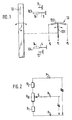
- FIG. 1 shows a schematic arrangement illustration
- FIG. 2 shows the circuit diagram of the potentiometer on the movable transmitter part
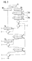
- FIG. 3 shows the adjustment method using a block diagram.
- Figure 1 shows a side view of a fuel injection pump of the distributor type with an actuator 10 controlling the fuel injection quantity in the form of an adjusting lever 10 which engages in a known manner in the controller of the fuel injection pump and z.
- B. arbitrarily controls a control spring bias.
- This adjustment lever 10 is pivotable between two fixed, adjustable stops, the stop 11 for the full load operating point and the stop 12 for the idle operating point.
- the movement of the adjusting lever 10 is transmitted to a displacement sensor 13 coupled to the fuel injection pump.
- the displacement sensor 13 can operate according to different principles, for example it can be designed as an inductive, capacitive or resistance sensor.
- a resistance sensor is assumed, for example, since the movement of the adjusting lever here is a rotary movement, in the form of a rotary potentiometer 13.
- the rotary potentiometer 13 is rotatably attached to the fuel injection pump with the aid of detachable fastening elements. This allows a presetting in relation to the rotational position of the adjusting lever and an adjustment of part tolerances.
- two additional stops 3 and 4 are attached to the fuel injection pump in a stationary and adjustable manner, with reference to the adjusting lever 10, either next to the swivel plane in the swivel range or, as described in more detail, in the swivel plane outside the swivel range .
- the stops 3 and 4 can be brought into effect both on the potentiometer 13 and on the adjusting lever 10; they are approached with aids, in the present case by means of a distance gauge 14, which, placed on the stops 3 and 4 lying outside the pivot range, causes the stops 3 and 4 extended by the distance gauge 14 to temporarily, during the placement process, into the pivot range of the adjustment lever 10 arrive and form the transformation stops 103 and 104 here.
- this grinder S is, depending on the translation of the coupling, by an identical or changed angular amount, which is caused by the two transformation stops 103 and 104 is specified, rotatable on a resistance track R B.
- the resistance track R B , two matching resistors R 1 and R 2 and the potentiometer housing form the fixed part 132 of the position sensor 13.
- the resistance track R B is connected symmetrically according to FIG. 2 in a series circuit with the adjustment resistors R 1 and R 2.
- connection points namely at R1 the point P3 and at R2 the point P2.
- the sliding on R B grinder S of the movable part 131 of the position sensor 13 has at its end facing away from the resistance path R B the connection point P 1. Between the connection points P2 and P3 is the
- Operating voltage U B synonymous with the supply voltage U V , applied.
- a differently sized output voltage U A can be removed between the connection points P 1 and P 3. It represents a certain amount of fuel in the control map of the fuel injection pump for each speed.
- the assignment of the angle of rotation on the potentiometer 13 to the fuel quantity is dependent on the pump specimen within the range between the two transformation stops 103 and 104. This dependency is eliminated by the method for setting the displacement sensor 13, in short the adjustment method.
- FIG. 3 schematically shows elements of the matching method in a block diagram.
- the stops 3 and 4 are extended by attaching the distance gauge 14. This creates the transformation stops 103 and 104. These are moved one after the other by the adjusting lever 10 and the stops 3 and 4 are set such that when the adjusting lever 10 is in contact with the transformation stop 103 a predetermined reference point in the controller map near the full load range and when the adjusting lever 10 is in contact a predetermined reference point in the controller map in the lower partial load range is reached at the transformation stop 104.
- the stops 3 and 4 are fixed and thus indirectly form the mark for the adjusting lever 10.
- the fuel injection pump After pre-assembly of the potentiometer 13 on the fuel injection pump and electrical contacting of the potentiometer 13, the fuel injection pump is preset in the sense of the following adjustment procedure according to Figure 3, which is on a test bench stationary fuel injection pump is made.
- the adjusting lever 10 is moved to a marked position, in Figure 3 to the transformation stop 103.
- the grinder S coupled to the adjusting lever 10 is moved to R B until a predetermined voltage U 1 is reached as the output voltage U A between the connection points P1 and P3.
- the housing of the potentiometer 13 is permanently fixed, the basic setting of the potentiometer 13 is thus completed. Then the actual voltage U3 is measured between the connection points P1 and P3.
- the setting lever 10 is rotated into the second marked position, in FIG. 3 against the transformation stop 104.
- the grinder S follows this rotation on the now fixed resistance track R B.
- the actual voltage U4 is removable between P1 and P3 as an electrical control signal.
- Both electrical control signals in the form of the actual voltages U3 and U4 are compared with predetermined target signals in the form of target voltages U3 * and U4 *, the signal deviations are determined and correction values are calculated therefrom.
- These correction values are implemented by means of laser trimming> ie from a laser device, the beam of which burns off parts of the balancing resistors R 1 and R 2, and thus their resistance values change to the pre-calculated extent.
- the adjustment process is completed when after this first adjustment cycle after moving the control lever 10 to the transformation stops 103 and 104, the deviations of the actual voltages U3 and U4 to the target voltages U3 * and U4 * lie within a predetermined tolerance range. If this is not yet achieved, a further adjustment cycle is started. Is the matching procedure completed, the distance gauge 14 is removed, the adjustment opening on the potentiometer 13 is closed with a cover cap, and thus influences which change the adjustment result are kept away from the resistance circuit in the potentiometer 13.
Landscapes
- Engineering & Computer Science (AREA)
- Chemical & Material Sciences (AREA)
- Combustion & Propulsion (AREA)
- Mechanical Engineering (AREA)
- General Engineering & Computer Science (AREA)
- Computer Hardware Design (AREA)
- Microelectronics & Electronic Packaging (AREA)
- Electrical Control Of Air Or Fuel Supplied To Internal-Combustion Engine (AREA)
- Fuel-Injection Apparatus (AREA)
- High-Pressure Fuel Injection Pump Control (AREA)
- Measuring Volume Flow (AREA)
- Combined Controls Of Internal Combustion Engines (AREA)
Applications Claiming Priority (2)
| Application Number | Priority Date | Filing Date | Title |
|---|---|---|---|
| DE3810853A DE3810853A1 (de) | 1988-03-30 | 1988-03-30 | Verfahren zur einstellung eines weggebers |
| DE3810853 | 1988-03-30 |
Publications (3)
| Publication Number | Publication Date |
|---|---|
| EP0335094A2 true EP0335094A2 (fr) | 1989-10-04 |
| EP0335094A3 EP0335094A3 (fr) | 1991-01-23 |
| EP0335094B1 EP0335094B1 (fr) | 1993-01-07 |
Family
ID=6351103
Family Applications (1)
| Application Number | Title | Priority Date | Filing Date |
|---|---|---|---|
| EP89102670A Expired - Lifetime EP0335094B1 (fr) | 1988-03-30 | 1989-02-16 | Dispositif de calibrage d'un capteur de position |
Country Status (5)
| Country | Link |
|---|---|
| US (1) | US4912968A (fr) |
| EP (1) | EP0335094B1 (fr) |
| JP (1) | JP2758197B2 (fr) |
| KR (1) | KR0137145B1 (fr) |
| DE (2) | DE3810853A1 (fr) |
Cited By (1)
| Publication number | Priority date | Publication date | Assignee | Title |
|---|---|---|---|---|
| EP0798542A1 (fr) * | 1996-03-30 | 1997-10-01 | Hella KG Hueck & Co. | Capteur de position d'une pédale d'accélérateur |
Families Citing this family (5)
| Publication number | Priority date | Publication date | Assignee | Title |
|---|---|---|---|---|
| DE4446905C2 (de) * | 1994-12-27 | 1996-12-05 | Anton Dipl Ing Dolenc | Einspritzpumpeneinheit und Verfahren zu deren Einstellung |
| IT1286101B1 (it) * | 1996-06-17 | 1998-07-07 | Same Spa Ora Same Deutz Fahr S | Dispositivo elettronico di regolazione della velocita' di rotazione del motore di una trattrice agricola |
| DE10208993B4 (de) * | 2002-02-28 | 2008-01-03 | Audi Ag | Diagnose eines Motorsteuerungssystems mit Lagerückmeldung |
| WO2007087705A1 (fr) * | 2006-02-01 | 2007-08-09 | Litens Automotive Partnership | système et procédé pour étalonner un capteur de position absolue |
| CN105068589B (zh) * | 2015-07-08 | 2018-01-30 | 上海新跃联汇电子科技有限公司 | 一种电阻式位置传感器输出曲线修刻算法 |
Family Cites Families (11)
| Publication number | Priority date | Publication date | Assignee | Title |
|---|---|---|---|---|
| FR2202538A5 (fr) * | 1972-10-05 | 1974-05-03 | Denis Gandard Ets | |
| JPS5028354A (fr) * | 1973-07-13 | 1975-03-22 | ||
| US3854464A (en) * | 1973-10-12 | 1974-12-17 | E Reinhard | Tool for adjusting diesel governors |
| DE7717931U1 (de) * | 1977-06-07 | 1978-11-23 | Robert Bosch Gmbh, 7000 Stuttgart | Steuereinrichtung fuer einspritzbrennkraftmaschinen |
| GB2049946B (en) * | 1979-05-23 | 1983-12-21 | Lucas Industries Ltd | Transducer calibration device |
| DE2942493A1 (de) * | 1979-10-20 | 1981-04-30 | Robert Bosch Gmbh, 7000 Stuttgart | Kraftstoffeinspritzpumpe fuer brennkraftmaschinen |
| DE2949018A1 (de) * | 1979-12-06 | 1981-06-11 | Robert Bosch Gmbh, 7000 Stuttgart | Verfahren zum winkelgerechten anbau einer kraftstoffeinspritzpumpe an eine brennkraftmaschine |
| JPS5891339A (ja) * | 1981-11-24 | 1983-05-31 | Japan Electronic Control Syst Co Ltd | 内燃機関の分配型燃料噴射装置 |
| DE3148687A1 (de) * | 1981-12-09 | 1983-06-16 | Robert Bosch Gmbh, 7000 Stuttgart | Kraftstoffeinspritzpumpe |
| JPS59160040A (ja) * | 1983-03-01 | 1984-09-10 | Diesel Kiki Co Ltd | 電子制御式燃料噴射ポンプ |
| US4557140A (en) * | 1983-11-23 | 1985-12-10 | Mcfarland Douglas F | Horsepower and fuel consumption gauge |
-
1988
- 1988-03-30 DE DE3810853A patent/DE3810853A1/de not_active Withdrawn
-
1989
- 1989-02-16 EP EP89102670A patent/EP0335094B1/fr not_active Expired - Lifetime
- 1989-02-16 DE DE8989102670T patent/DE58903196D1/de not_active Expired - Lifetime
- 1989-03-22 US US07/327,441 patent/US4912968A/en not_active Expired - Lifetime
- 1989-03-28 KR KR1019890003867A patent/KR0137145B1/ko not_active Expired - Fee Related
- 1989-03-28 JP JP1074142A patent/JP2758197B2/ja not_active Expired - Lifetime
Cited By (1)
| Publication number | Priority date | Publication date | Assignee | Title |
|---|---|---|---|---|
| EP0798542A1 (fr) * | 1996-03-30 | 1997-10-01 | Hella KG Hueck & Co. | Capteur de position d'une pédale d'accélérateur |
Also Published As
| Publication number | Publication date |
|---|---|
| JPH01300058A (ja) | 1989-12-04 |
| DE58903196D1 (de) | 1993-02-18 |
| EP0335094A3 (fr) | 1991-01-23 |
| KR890014869A (ko) | 1989-10-25 |
| KR0137145B1 (ko) | 1998-04-25 |
| US4912968A (en) | 1990-04-03 |
| EP0335094B1 (fr) | 1993-01-07 |
| DE3810853A1 (de) | 1989-10-12 |
| JP2758197B2 (ja) | 1998-05-28 |
Similar Documents
| Publication | Publication Date | Title |
|---|---|---|
| DE3447896C2 (fr) | ||
| DE2941977A1 (de) | Einrichtung zum optimieren von betriebskenngroessen einer brennkraftmaschine | |
| EP0335094B1 (fr) | Dispositif de calibrage d'un capteur de position | |
| EP0375710B1 (fr) | Systeme de reglage (commande et/ou ajustement) pour vehicules a moteur | |
| DE3002015C2 (fr) | ||
| DE4135913C2 (de) | Einrichtung zur Steuerung einer Verstelleinrichtung in einem mit einer Antriebseinheit ausgestatteten Fahrzeug | |
| DE2544791C2 (fr) | ||
| DE3227805A1 (de) | Elektrisches potentiometer | |
| EP0360790B1 (fr) | Dispositif et procédé pour mesurer la température du carburant dans un moteur à combustion interne réglé électroniquement | |
| DE4420122B4 (de) | Verfahren und Vorrichtung zur Bestimmung einer Endstellung einer Verstelleinrichtung in Fahrzeugen | |
| DE2932291A1 (de) | Elektrischer druckschalter | |
| EP0029019B1 (fr) | Installation de régulation pour moteurs à combustion interne | |
| DE19751583A1 (de) | Vorrichtung zum Erfassen der Öffnung einer Drosselklappe | |
| EP0055245A2 (fr) | Dispositif pour le positionnement et la coordination d'une pluralité de dispositifs d'injection | |
| DE10150786C2 (de) | Verfahren und Vorrichtung zum automatischen Einstellen von Injektoren | |
| DE19603778A1 (de) | Verfahren und Vorrichtung zum Steuern eines eine Drosselventilverschmutzung betreffenden Lernens | |
| DE3430551C2 (de) | Einrichtung zur Änderung von gespeicherten Kenngrößen in elektronischen Steuergeräten für insbesondere Brennkraftmaschinen | |
| EP0708233B1 (fr) | Procédé et dispositif pour commander un moteur à combustion interne | |
| DE19853329A1 (de) | Prüfverfahren für eine Baugruppe mit einem zu verstellenden Element, insbesondere mit einer Drosselklappe, dessen Stellbewegung von einem elektrischen Stellmotor bewirkt wird | |
| DE4340614A1 (de) | Vorrichtung zur Verdrehung einer Nockenwelle gegenüber der Kurbelwelle in Kraftfahrzeugen | |
| DE2526662C3 (fr) | ||
| DE4340372A1 (de) | Verfahren zur Leerlauferkennung bei einer Lastverstelleinrichtung einer drosselklappengeregelten Brennkraftmaschine | |
| DE2932133A1 (de) | Mehrzylindrige brennkraftmaschine, insbesondere fuer kraftfahrzeuge | |
| DE4115288C2 (de) | Einrichtung zum Abgleich von Exemplarstreuung und Temperatureinflüssen mindestens eines Sensors | |
| DE4334720B4 (de) | Verfahren und Vorrichtung zur Steuerung einer Verstelleinrichtung bei Fahrzeugen |
Legal Events
| Date | Code | Title | Description |
|---|---|---|---|
| PUAI | Public reference made under article 153(3) epc to a published international application that has entered the european phase |
Free format text: ORIGINAL CODE: 0009012 |
|
| AK | Designated contracting states |
Kind code of ref document: A2 Designated state(s): DE FR GB IT |
|
| PUAL | Search report despatched |
Free format text: ORIGINAL CODE: 0009013 |
|
| AK | Designated contracting states |
Kind code of ref document: A3 Designated state(s): DE FR GB IT |
|
| 17P | Request for examination filed |
Effective date: 19910521 |
|
| R17P | Request for examination filed (corrected) |
Effective date: 19910621 |
|
| RAP3 | Party data changed (applicant data changed or rights of an application transferred) |
Owner name: ROBERT BOSCH GMBH |
|
| 17Q | First examination report despatched |
Effective date: 19920121 |
|
| GRAA | (expected) grant |
Free format text: ORIGINAL CODE: 0009210 |
|
| AK | Designated contracting states |
Kind code of ref document: B1 Designated state(s): DE FR GB IT |
|
| ET | Fr: translation filed | ||
| REF | Corresponds to: |
Ref document number: 58903196 Country of ref document: DE Date of ref document: 19930218 |
|
| GBT | Gb: translation of ep patent filed (gb section 77(6)(a)/1977) |
Effective date: 19930122 |
|
| ITF | It: translation for a ep patent filed | ||
| PLBE | No opposition filed within time limit |
Free format text: ORIGINAL CODE: 0009261 |
|
| STAA | Information on the status of an ep patent application or granted ep patent |
Free format text: STATUS: NO OPPOSITION FILED WITHIN TIME LIMIT |
|
| 26N | No opposition filed | ||
| REG | Reference to a national code |
Ref country code: GB Ref legal event code: IF02 |
|
| PGFP | Annual fee paid to national office [announced via postgrant information from national office to epo] |
Ref country code: IT Payment date: 20080227 Year of fee payment: 20 Ref country code: GB Payment date: 20080222 Year of fee payment: 20 |
|
| PGFP | Annual fee paid to national office [announced via postgrant information from national office to epo] |
Ref country code: DE Payment date: 20080428 Year of fee payment: 20 Ref country code: FR Payment date: 20080219 Year of fee payment: 20 |
|
| REG | Reference to a national code |
Ref country code: GB Ref legal event code: PE20 Expiry date: 20090215 |
|
| PG25 | Lapsed in a contracting state [announced via postgrant information from national office to epo] |
Ref country code: GB Free format text: LAPSE BECAUSE OF EXPIRATION OF PROTECTION Effective date: 20090215 |