EP0335094A2 - Apparatus for the calibration of a position sensor - Google Patents
Apparatus for the calibration of a position sensor Download PDFInfo
- Publication number
- EP0335094A2 EP0335094A2 EP19890102670 EP89102670A EP0335094A2 EP 0335094 A2 EP0335094 A2 EP 0335094A2 EP 19890102670 EP19890102670 EP 19890102670 EP 89102670 A EP89102670 A EP 89102670A EP 0335094 A2 EP0335094 A2 EP 0335094A2
- Authority
- EP
- European Patent Office
- Prior art keywords
- fuel injection
- displacement sensor
- injection pump
- potentiometer
- operating points
- Prior art date
- Legal status (The legal status is an assumption and is not a legal conclusion. Google has not performed a legal analysis and makes no representation as to the accuracy of the status listed.)
- Granted
Links
Images
Classifications
-
- F—MECHANICAL ENGINEERING; LIGHTING; HEATING; WEAPONS; BLASTING
- F02—COMBUSTION ENGINES; HOT-GAS OR COMBUSTION-PRODUCT ENGINE PLANTS
- F02D—CONTROLLING COMBUSTION ENGINES
- F02D41/00—Electrical control of supply of combustible mixture or its constituents
- F02D41/30—Controlling fuel injection
-
- F—MECHANICAL ENGINEERING; LIGHTING; HEATING; WEAPONS; BLASTING
- F02—COMBUSTION ENGINES; HOT-GAS OR COMBUSTION-PRODUCT ENGINE PLANTS
- F02D—CONTROLLING COMBUSTION ENGINES
- F02D41/00—Electrical control of supply of combustible mixture or its constituents
- F02D41/24—Electrical control of supply of combustible mixture or its constituents characterised by the use of digital means
- F02D41/26—Electrical control of supply of combustible mixture or its constituents characterised by the use of digital means using computer, e.g. microprocessor
- F02D41/28—Interface circuits
-
- F—MECHANICAL ENGINEERING; LIGHTING; HEATING; WEAPONS; BLASTING
- F02—COMBUSTION ENGINES; HOT-GAS OR COMBUSTION-PRODUCT ENGINE PLANTS
- F02D—CONTROLLING COMBUSTION ENGINES
- F02D41/00—Electrical control of supply of combustible mixture or its constituents
- F02D41/30—Controlling fuel injection
- F02D41/38—Controlling fuel injection of the high pressure type
- F02D41/40—Controlling fuel injection of the high pressure type with means for controlling injection timing or duration
- F02D41/406—Electrically controlling a diesel injection pump
-
- F—MECHANICAL ENGINEERING; LIGHTING; HEATING; WEAPONS; BLASTING
- F02—COMBUSTION ENGINES; HOT-GAS OR COMBUSTION-PRODUCT ENGINE PLANTS
- F02D—CONTROLLING COMBUSTION ENGINES
- F02D2200/00—Input parameters for engine control
- F02D2200/02—Input parameters for engine control the parameters being related to the engine
- F02D2200/04—Engine intake system parameters
- F02D2200/0404—Throttle position
-
- F—MECHANICAL ENGINEERING; LIGHTING; HEATING; WEAPONS; BLASTING
- F02—COMBUSTION ENGINES; HOT-GAS OR COMBUSTION-PRODUCT ENGINE PLANTS
- F02D—CONTROLLING COMBUSTION ENGINES
- F02D2250/00—Engine control related to specific problems or objectives
- F02D2250/16—End position calibration, i.e. calculation or measurement of actuator end positions, e.g. for throttle or its driving actuator
-
- Y—GENERAL TAGGING OF NEW TECHNOLOGICAL DEVELOPMENTS; GENERAL TAGGING OF CROSS-SECTIONAL TECHNOLOGIES SPANNING OVER SEVERAL SECTIONS OF THE IPC; TECHNICAL SUBJECTS COVERED BY FORMER USPC CROSS-REFERENCE ART COLLECTIONS [XRACs] AND DIGESTS
- Y02—TECHNOLOGIES OR APPLICATIONS FOR MITIGATION OR ADAPTATION AGAINST CLIMATE CHANGE
- Y02T—CLIMATE CHANGE MITIGATION TECHNOLOGIES RELATED TO TRANSPORTATION
- Y02T10/00—Road transport of goods or passengers
- Y02T10/10—Internal combustion engine [ICE] based vehicles
- Y02T10/40—Engine management systems
Definitions
- the invention is based on a method according to the preamble of claim 1.
- the method according to the invention with the characterizing features of claim 1 has the advantage that the setting of the displacement sensor can be carried out on a preset and stationary fuel injection pump, the presetting being reproducible by marked positions of the actuating part.
- the device according to the invention for carrying out the method with the characterizing features of claim 3 has the advantage that operating points in the map of the fuel injection pump are marked by additional stops that are set with a distance gauge, which points a load signal with an exact, constant for all pumps Embody quantity assignment.
- the necessary adjustment of the characteristic of the displacement sensor is carried out in a control loop largely without mechanical aids and thus improves the reproducibility of the characteristic values and thus the quantity assignment.
- the balancing resistors are installed in the fixed part of the encoder so that they are easily accessible through a lockable opening.
- the resistance values achieved by partially burning off the resistance track with a laser beam are fixed in a stable manner.
- This type of comparison can be automated well; It is also possible to run through several adjustment cycles until the accuracy falls below a predetermined accuracy limit. There is no longer a risk of subjective adjustment associated with the adjustment hysteresis of mechanical adjustment elements.
- FIG. 1 shows a schematic arrangement illustration
- FIG. 2 shows the circuit diagram of the potentiometer on the movable transmitter part
- FIG. 3 shows the adjustment method using a block diagram.
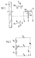
- Figure 1 shows a side view of a fuel injection pump of the distributor type with an actuator 10 controlling the fuel injection quantity in the form of an adjusting lever 10 which engages in a known manner in the controller of the fuel injection pump and z.
- B. arbitrarily controls a control spring bias.
- This adjustment lever 10 is pivotable between two fixed, adjustable stops, the stop 11 for the full load operating point and the stop 12 for the idle operating point.
- the movement of the adjusting lever 10 is transmitted to a displacement sensor 13 coupled to the fuel injection pump.
- the displacement sensor 13 can operate according to different principles, for example it can be designed as an inductive, capacitive or resistance sensor.
- a resistance sensor is assumed, for example, since the movement of the adjusting lever here is a rotary movement, in the form of a rotary potentiometer 13.
- the rotary potentiometer 13 is rotatably attached to the fuel injection pump with the aid of detachable fastening elements. This allows a presetting in relation to the rotational position of the adjusting lever and an adjustment of part tolerances.
- two additional stops 3 and 4 are attached to the fuel injection pump in a stationary and adjustable manner, with reference to the adjusting lever 10, either next to the swivel plane in the swivel range or, as described in more detail, in the swivel plane outside the swivel range .
- the stops 3 and 4 can be brought into effect both on the potentiometer 13 and on the adjusting lever 10; they are approached with aids, in the present case by means of a distance gauge 14, which, placed on the stops 3 and 4 lying outside the pivot range, causes the stops 3 and 4 extended by the distance gauge 14 to temporarily, during the placement process, into the pivot range of the adjustment lever 10 arrive and form the transformation stops 103 and 104 here.
- this grinder S is, depending on the translation of the coupling, by an identical or changed angular amount, which is caused by the two transformation stops 103 and 104 is specified, rotatable on a resistance track R B.
- the resistance track R B , two matching resistors R 1 and R 2 and the potentiometer housing form the fixed part 132 of the position sensor 13.
- the resistance track R B is connected symmetrically according to FIG. 2 in a series circuit with the adjustment resistors R 1 and R 2.
- connection points namely at R1 the point P3 and at R2 the point P2.
- the sliding on R B grinder S of the movable part 131 of the position sensor 13 has at its end facing away from the resistance path R B the connection point P 1. Between the connection points P2 and P3 is the
- Operating voltage U B synonymous with the supply voltage U V , applied.
- a differently sized output voltage U A can be removed between the connection points P 1 and P 3. It represents a certain amount of fuel in the control map of the fuel injection pump for each speed.
- the assignment of the angle of rotation on the potentiometer 13 to the fuel quantity is dependent on the pump specimen within the range between the two transformation stops 103 and 104. This dependency is eliminated by the method for setting the displacement sensor 13, in short the adjustment method.
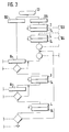
- FIG. 3 schematically shows elements of the matching method in a block diagram.
- the stops 3 and 4 are extended by attaching the distance gauge 14. This creates the transformation stops 103 and 104. These are moved one after the other by the adjusting lever 10 and the stops 3 and 4 are set such that when the adjusting lever 10 is in contact with the transformation stop 103 a predetermined reference point in the controller map near the full load range and when the adjusting lever 10 is in contact a predetermined reference point in the controller map in the lower partial load range is reached at the transformation stop 104.
- the stops 3 and 4 are fixed and thus indirectly form the mark for the adjusting lever 10.
- the fuel injection pump After pre-assembly of the potentiometer 13 on the fuel injection pump and electrical contacting of the potentiometer 13, the fuel injection pump is preset in the sense of the following adjustment procedure according to Figure 3, which is on a test bench stationary fuel injection pump is made.
- the adjusting lever 10 is moved to a marked position, in Figure 3 to the transformation stop 103.
- the grinder S coupled to the adjusting lever 10 is moved to R B until a predetermined voltage U 1 is reached as the output voltage U A between the connection points P1 and P3.
- the housing of the potentiometer 13 is permanently fixed, the basic setting of the potentiometer 13 is thus completed. Then the actual voltage U3 is measured between the connection points P1 and P3.
- the setting lever 10 is rotated into the second marked position, in FIG. 3 against the transformation stop 104.
- the grinder S follows this rotation on the now fixed resistance track R B.
- the actual voltage U4 is removable between P1 and P3 as an electrical control signal.
- Both electrical control signals in the form of the actual voltages U3 and U4 are compared with predetermined target signals in the form of target voltages U3 * and U4 *, the signal deviations are determined and correction values are calculated therefrom.
- These correction values are implemented by means of laser trimming> ie from a laser device, the beam of which burns off parts of the balancing resistors R 1 and R 2, and thus their resistance values change to the pre-calculated extent.
- the adjustment process is completed when after this first adjustment cycle after moving the control lever 10 to the transformation stops 103 and 104, the deviations of the actual voltages U3 and U4 to the target voltages U3 * and U4 * lie within a predetermined tolerance range. If this is not yet achieved, a further adjustment cycle is started. Is the matching procedure completed, the distance gauge 14 is removed, the adjustment opening on the potentiometer 13 is closed with a cover cap, and thus influences which change the adjustment result are kept away from the resistance circuit in the potentiometer 13.
Landscapes
- Engineering & Computer Science (AREA)
- Chemical & Material Sciences (AREA)
- Combustion & Propulsion (AREA)
- Mechanical Engineering (AREA)
- General Engineering & Computer Science (AREA)
- Computer Hardware Design (AREA)
- Microelectronics & Electronic Packaging (AREA)
- Electrical Control Of Air Or Fuel Supplied To Internal-Combustion Engine (AREA)
- Fuel-Injection Apparatus (AREA)
- High-Pressure Fuel Injection Pump Control (AREA)
- Combined Controls Of Internal Combustion Engines (AREA)
- Measuring Volume Flow (AREA)
Abstract
Kraftfahrzeugkomponenten, die abhängig von dem Betriebszustand einer Kraftstoffeinspritzpumpe arbeiten, benötigen von dieser ein Lastsignal, das eine genaue Mengenzuordnung repräsentiert, damit sie angepaßt arbeiten können. Die genaue Mengenzuordnung wird dadurch erzielt, daß zuerst auf mechanischem Wege zwei zusätzliche Anschläge (3 und 4), vorübergehend verlängert um eine Distanzlehre (14), an der Pumpe die Drehung eines Verstellhebels (10) begrenzen. Die Umsetzung in ein elektrisches Signal erfolgt über ein mit dem Verstellhebel (10) gekoppelten Potentiometer (13), dessen Kennlinie in einem Abgleichverfahren durch Lasertrimmen von zwei, mit dem Potentiometer (13) in Reihe geschalteter Vorwiderstände so erfolgt, daß die Sollspannungen, denen vorbestimmte Mengen zugeordnet sind, an den beiden Anschlägen erreicht werden. Diese Bezugsspannung eignet sich zur Ansteuerung von Folgekomponenten der Kraftstoffeinspritzpumpe.Motor vehicle components, which work depending on the operating state of a fuel injection pump, require a load signal from the latter, which represents an exact quantity assignment, so that they can work in an adapted manner. The exact quantity assignment is achieved by first mechanically limiting two additional stops (3 and 4), temporarily extended by a distance gauge (14), on the pump, the rotation of an adjusting lever (10). The conversion into an electrical signal takes place via a potentiometer (13) coupled to the adjusting lever (10), the characteristic curve of which takes place in a calibration process by laser trimming of two series resistors connected in series with the potentiometer (13) so that the target voltages are predetermined Quantities are assigned to be reached at the two stops. This reference voltage is suitable for controlling subsequent components of the fuel injection pump.
Description
Die Erfindung geht aus von einem Verfahren nach der Gattung des Anspruchs 1.The invention is based on a method according to the preamble of claim 1.
Es ist aus der DE-OS 3339077 bekannt, die Stellung eines Stellorgans einer Kraftstoffeinspritzpumpe auf ein potentiometer zu übertragen, dessen Schleiferspannung dann die Lage des Stellorgans definiert. Bei diesem Verfahren wird ein solchermaßen offenbarter Weggeber durch Verschiebung des Potentiometers selbst und durch die mechanische Einstellung eines Abgleichwiderstandes bei laufender Kraftstoffeinspritzpumpe eingestellt. Diese für eine Serienproduktion aufwendige Abgleichprozedur mit Hilfe mechanisch betätigter Einstellglieder, die einerseits wegen ihrer Anordnung innerhalb eines Gehäuses schwer zugänglich sind, andererseits eine durch die mechanische Verstellung prinzipiell vorhandene Einstellspielhysterese aufweisen, führen nach dem Abgleichvorgang in nachteiliger Weise zu einer Bezugsspannung, deren Konstanz den heutigen Genauigkeitsanforderungen in Verbindung mit einer wirtschaftlich durchzuführenden Fertigung nicht mehr genügt.It is known from DE-OS 3339077 to transfer the position of an actuator of a fuel injection pump to a potentiometer, the wiper voltage of which then defines the position of the actuator. In this method, a displacement sensor disclosed in this way is set by shifting the potentiometer itself and by mechanically adjusting a balancing resistor while the fuel injection pump is running. This adjustment procedure, which is complex for series production, with the aid of mechanically actuated setting elements, which on the one hand are difficult to access due to their arrangement within a housing, and on the other hand have an adjustment play hysteresis that is in principle present due to the mechanical adjustment, lead disadvantageously to a reference voltage after the adjustment process, the constancy of which is today's Accuracy requirements in connection with economically feasible production are no longer sufficient.
Das erfindungsgemäße Verfahren mit den kennzeichnenden Merkmalen des Anspruchs 1 hat demgegenüber den Vorteil, daß die Einstellung des Weggebers an einer voreingestellten und stillstehenden Kraftstoffeinspritzpumpe erfolgen kann, wobei die Voreinstellung durch markierte Lagen des Stellteils reproduzierbar ist.The method according to the invention with the characterizing features of claim 1 has the advantage that the setting of the displacement sensor can be carried out on a preset and stationary fuel injection pump, the presetting being reproducible by marked positions of the actuating part.
Die erfindungsgemäße Vorrichtung zur Durchführung des Verfahrens mit den kennzeichnenden Merkmalen des Anspruchs 3 hat demgegenüber den Vorteil, daß durch zusätzliche Anschläge, die mit einer Distanzlehre eingestellt werden, Betriebspunkte im Kennfeld der Kraftstoffeinspritzpumpe markiert werden, die ein Lastsignal mit einer, bei allen Pumpen gleichbleibenden genauen Mengenzuordnung verkörpern. Die dazu notwendige Anpassung der Kennlinie des Weggebers erfolgt in einem Regelkreis weitgehend ohne mechanische Hilfsmittel und verbessert so die Reproduzierbarkeit der Kennlinienwerte und damit die Mengenzuordnung.The device according to the invention for carrying out the method with the characterizing features of
Die Abgleichswiderstände sind im ortsfesten Teil des Weggebers so eingebaut, daß sie durch eine verschließbare Öffnung gut zugänglich sind. Die durch das partielle Abbrennen der Widerstandsbahn durch Laserstrahl erzielten Widerstandswerte sind stabil fixiert.The balancing resistors are installed in the fixed part of the encoder so that they are easily accessible through a lockable opening. The resistance values achieved by partially burning off the resistance track with a laser beam are fixed in a stable manner.
Diese Art des Abgleichs ist gut automatisierbar; es können auch mehrere Abgleichszyklen durchlaufen werden, bis eine vorgegebene Genauigkeitsschranke unterschritten wird. Die Gefahr einer subjektiven Einstellung, verbunden mit der Einstellspielhysterese mechanischer Einstellglieder besteht nicht mehr.This type of comparison can be automated well; It is also possible to run through several adjustment cycles until the accuracy falls below a predetermined accuracy limit. There is no longer a risk of subjective adjustment associated with the adjustment hysteresis of mechanical adjustment elements.
Die Erfindung ist in der Zeichnung anhand mehrerer Figuren dargestellt und in der nachfolgenden Beschreibung näher erläutert. Es zeigen Figur 1 eine schematische Anordnungsdarstellung, Figur 2 das Schaltbild des Potentiometers am beweglichen Geberteil und Figur 3 das Abgleichverfahren anhand eines Blockdiagramms.The invention is illustrated in the drawing using several figures and explained in more detail in the following description. FIG. 1 shows a schematic arrangement illustration, FIG. 2 shows the circuit diagram of the potentiometer on the movable transmitter part and FIG. 3 shows the adjustment method using a block diagram.
Figur 1 zeigt in der Seitenansicht eine Kraftstoffeinspritzpumpe der Verteilerbauart mit einem die Kraftstoffeinspritzmenge steuernden Stellteils 10 in Form eines Verstellhebels 10, der in bekannter Weise in den Regler der Kraftstoffeinspritzpumpe eingreift und z. B. eine Regelfedervorspannung willkürlich steuert. Dieser Verstellhebel 10 ist schwenkbar zwischen zwei ortsfesten, einstellbaren Anschlägen, dem Anschlag 11 für den Betriebspunkt Vollast und den Anschlag 12 für den Betriebspunkt Leerlauf. Die Bewegung des Verstellhebels 10 wird übertragen auf ein mit der Kraftstoffeinspritzpumpe gekoppelten Weggeber 13. Der Weggeber 13 kann nach unterschiedlichen Prinzipien arbeiten, beispielsweise kann er als Induktiv-, Kapazitiv- oder Widerstandsgeber ausgebildet sein. In der nachfolgenden Beschreibung wird von einem Widerstandsgeber ausgegangen, und zwar beispielsweise, da die Bewegung des Verstellhebels hier als Drehbewegung vorliegt, in Form eines Drehpotentiometers 13. Das Drehpotentiometer 13 ist an der Kraftstof feinspritzpumpe mit Hilfe lösbarer Befestigungselemente verdrehbar befestigt. Dies erlaubt eine Voreinstellung in bezug auf die Drehlage des Verstellhebels und ein Ansgleich von Teiletoleranzen.Figure 1 shows a side view of a fuel injection pump of the distributor type with an
An der Kraftstoffeinspritzpumpe sind neben den Anschlägen 11 und 12 zwei zusätzliche Anschläge 3 und 4 ortsfest und einstellbar angebracht, und zwar, bezogen auf den Verstellhebel 10, entweder neben der Schwenkebene im Schwenkbereich, oder, wie noch näher beschrieben, in der Schwenkebene außerhalb des Schwenkbereichs. Die Anschläge 3 und 4 können sowohl auf das Potentiometer 13 als auch auf den Verstellhebel 10 zur Wirkung gebracht werden; sie werden mit Hilfsmitteln, im vorliegenden Fall mittels einer Distanzlehre 14 angefahren, die, auf die außerhalb des Schwenkbereichs liegenden Anschläge 3 und 4 gesetzt, bewirkt, daß die um die Distanzlehre 14 verlängerten Anschläge 3 und 4 vorübergehend, während des Aufsetzvorgangs, in den Schwenkbereich des Verstellhebels 10 gelangen und hier die Transformationsanschläge 103 und 104 bilden. Dadurch sind zwei Lagen und damit zwei Betriebspunkte im Kraftstoffpumpenkennfeld Einspritzmenge über Drehzahl, kurz Reglerkennfeld, markiert. Durch die Kopplung des Verstellhebels 10 mit dem beweglichen Teil 131 des Weggebers 13, dargestellt durch die Achse und den Schleifer 5 des Potentiometers 13, ist dieser Schleifer S je nach Übersetzung der Kopplung um einen gleichen oder geänderten Winkelbetrag, der durch die beiden Transformationsanschläge 103 und 104 vorgegeben wird, auf einer Widerstandsbahn RB drehbar. Die Widerstandsbahn RB, zwei Angleichwiderstände R₁ und R₂ und das Potentiometergehäuse bilden den feststehenden Teil 132 des Weggebers 13. Die Widerstandsbahn RB ist entsprechend Figur 2 in einer Reihenschaltung symetrisch mit den Abgleichwiderständen R₁ und R₂ verbunden. Die von RB abgewandten Enden der Abgleichwiderstände bilden Anschlußpunkte, und zwar bei R₁ den Punkt P₃ und bei R₂ den Punkt P₂. Der auf RB gleitende Schleifer S des beweglichen Teils 131 des Weggebers 13 hat an seinem, der Widerstandsbahn RB abgewandten Ende den Anschlußpunkt P₁. Zwischen den Anschlußpunkten P₂ und P₃ ist dieIn addition to the stops 11 and 12, two
Betriebsspannung UB, gleichbedeutend mit der Versorgungsspannung UV, angelegt. Je nach Stellung des Schleifers S auf der Widerstandsbahn RB kann zwischen den Anschlußpunkten P₁ und P₃ eine unterschiedlich große Ausgangs spannung UA abgenommen werden. Sie repräsentiert im Reglerkennfeld der Kraftstoffeinspritzpumpe für jede Drehzahl eine bestimmte Kraftstoffmenge. Die Zuordnung für Drehwinkel am Potentiometer 13 zur Kraftstoffmenge ist innerhalb des Bereiches zwischen den beiden Transformationsanschlägen 103 und 104 vom Pumpenexemplar abhängig. Diese Abhängigkeit wird durch das Verfahren zur Einstellung des Weggebers 13, kurz Abgleichverfahren, beseitigt.Operating voltage U B , synonymous with the supply voltage U V , applied. Depending on the position of the grinder S on the resistance path R B , a differently sized output voltage U A can be removed between the connection points P 1 and
Figur 3 zeigt in einem Blockdiagramm schematisch Elemente des Abgleichverfahrens. Ausgehend von einer betriebenen Kraftstoffeinspritzpumpe, die auf einem Betriebsprüfstand montiert ist, werden die Anschläge 3 und 4 durch das Aufsetzen der Distanzlehre 14 verlängert. Es entstehen somit die Transformationsanschläge 103 und 104. Diese werden nacheinander von dem Verstellhebel 10 angefahren und die Anschläge 3 und 4 dabei so eingestellt, daß bei Anlage des Verstellhebels 10 am Transformationsanschlag 103 ein vorgegebener Bezugspunkt im Reglerkennfeld nahe des Vollastbereichs und bei Anlage des Verstellhebels 10 am Transformationsanschlag 104 ein vorgegebener Bezugspunkt im Reglerkennfeld im unteren Teillastbereich erreicht wird. Die Anschläge 3 und 4 werden fixiert und bilden somit mittelbar die Markierung für den Verstellhebel 10. Nach Vormontierung des Potentiometers 13 an die Kraftstoffeinspritzpumpe und elektrischer Kontaktierung des Potentiometers 13 ist die Kraftstoffeinspritzpumpe voreingestellt im Sinne des folgenden Abgleichverfahrens entsprechend Figur 3, welches auf einem Meßprüfstand bei stillstehender Kraftstoffeinspritzpumpe vorgenommen wird.FIG. 3 schematically shows elements of the matching method in a block diagram. Starting from an operated fuel injection pump, which is mounted on an operating test stand, the
Der Verstellhebel 10 wird in eine markierte Stellung gefahren, in Figur 3 an den Transformationsanschlag 103. Durch Drehung des Gehäuses des Potentiometers 13 und damit der Widerstandsbahn RB wird der mit dem Verstellhebel 10 gekoppelte Schleifer S auf RB verschoben, bis eine vorgegebene Spannung U₁ als Ausgangsspannung UA zwischen den Anschlußpunkten P₁ und P₃ erreicht wird. In dieser Position wird das Gehäuse des Potentiometers 13 bleibend fixiert, die Grundeinstellung des Potentiometers 13 somit abgeschlossen. Danach wird zwischen den Anschlußpunkten P₁ und P₃ die Ist-Spannung U₃ gemessen.The adjusting
In der Folge wird der Stellhebel 10 in die zweite markierte Stellung gedreht, in Figur 3 an den Transformationsanschlag 104. Der Schleifer S folgt dieser Drehung auf der nun ortsfesten Widerstandsbahn RB. Somit ist zwischen P₁ und P₃ als elektrisches Stellsignal die Istspannung U₄ abnehmbar. Beide elektrischen Stellsignale in Form der Istspannungen U₃ und U₄ werden mit vorgegebenen Sollsignalen in Form von Sollspannungen U₃* und U₄* verglichen, die Signalabweichungen festgestellt und daraus Korrekturwerte berechnet. Diese Korrekturwerte werden umgesetzt mittels Lasertrimmen> d. h. von einem Lasergerät, dessen Strahl Partien der Abgleichwiderstände R₁ und R₂ abbrennt, und so deren Widerstandswerte in dem vorberechneten Umfang ändert.As a result, the
Das Abgleichverfahren ist abgeschlossen, wenn nach diesem ersten Abgleichzyklus nach Anfahren des Stellhebels 10 an die Transformationsanschläge 103 und 104 die Abweichungen der Istspannungen U₃ und U₄ zu den sollspannungen U₃* und U₄* innerhalb eines vorgegebenen Toleranzbereichs liegen. Wird dies noch nicht erreicht, so wird ein weiterer Abgleichzyklus begonnen. Ist das Abgleichverfahren abgeschlossen, so wird die Distanzlehre 14 entfernt, mit einer Abdeckkappe die Abgleichöffnung am Potentiometer 13 verschlossen und damit das Abgleichergebnis verändernde Einflüsse von der Widerstandsschaltung im Potentiometer 13 ferngehalten.The adjustment process is completed when after this first adjustment cycle after moving the
Nunmehr steht zwischen den durch die Transformationsanschläge 103 und 104 zuvor definierten Lagen an den Anschlußpunkten P₁ und P₃ Normsteuerspannungen zur Verfügung, die auf einer vorgegebenen Kurve liegen. Mit dieser Normsteuerspannung, die dank des Abgleichverfahrens eine gleichbleibende, genaue Mengenzuordnung verkörpert, ist es möglich, beispielsweise Automatgetriebe, Abgasrückführventile oder mechanische Lader so anzusteuern, daß einerseits die heutigen hohen Genauigkeitsanforderungen konstant von Pumpe zu Pumpe erfüllt werden können und dieses Verfahren an einer stillstehenden Kraftstoffeinspritzpumpe in einer wirtschaftlich durchzuführenden Fertigung erreicht wird.Now there are standard control voltages between the positions previously defined by the
Claims (6)
Applications Claiming Priority (2)
| Application Number | Priority Date | Filing Date | Title |
|---|---|---|---|
| DE3810853A DE3810853A1 (en) | 1988-03-30 | 1988-03-30 | METHOD FOR ADJUSTING A SENSOR |
| DE3810853 | 1988-03-30 |
Publications (3)
| Publication Number | Publication Date |
|---|---|
| EP0335094A2 true EP0335094A2 (en) | 1989-10-04 |
| EP0335094A3 EP0335094A3 (en) | 1991-01-23 |
| EP0335094B1 EP0335094B1 (en) | 1993-01-07 |
Family
ID=6351103
Family Applications (1)
| Application Number | Title | Priority Date | Filing Date |
|---|---|---|---|
| EP89102670A Expired - Lifetime EP0335094B1 (en) | 1988-03-30 | 1989-02-16 | Apparatus for the calibration of a position sensor |
Country Status (5)
| Country | Link |
|---|---|
| US (1) | US4912968A (en) |
| EP (1) | EP0335094B1 (en) |
| JP (1) | JP2758197B2 (en) |
| KR (1) | KR0137145B1 (en) |
| DE (2) | DE3810853A1 (en) |
Cited By (1)
| Publication number | Priority date | Publication date | Assignee | Title |
|---|---|---|---|---|
| EP0798542A1 (en) * | 1996-03-30 | 1997-10-01 | Hella KG Hueck & Co. | Accelerator pedal position sensor |
Families Citing this family (5)
| Publication number | Priority date | Publication date | Assignee | Title |
|---|---|---|---|---|
| DE4446905C2 (en) * | 1994-12-27 | 1996-12-05 | Anton Dipl Ing Dolenc | Injection pump unit and method for its adjustment |
| IT1286101B1 (en) * | 1996-06-17 | 1998-07-07 | Same Spa Ora Same Deutz Fahr S | ELECTRONIC DEVICE FOR REGULATING THE ROTATION SPEED OF THE MOTOR OF AN AGRICULTURAL TRACTOR |
| DE10208993B4 (en) * | 2002-02-28 | 2008-01-03 | Audi Ag | Diagnosis of a motor control system with position feedback |
| EP1979721A4 (en) * | 2006-02-01 | 2013-11-20 | Litens Automotive Inc | System and method for calibrating an absolute position sensor |
| CN105068589B (en) * | 2015-07-08 | 2018-01-30 | 上海新跃联汇电子科技有限公司 | A kind of resistive position sensor curve of output repaiies quarter algorithm |
Citations (6)
| Publication number | Priority date | Publication date | Assignee | Title |
|---|---|---|---|---|
| FR2202538A5 (en) * | 1972-10-05 | 1974-05-03 | Denis Gandard Ets | |
| GB2049946A (en) * | 1979-05-23 | 1980-12-31 | Lucas Industries Ltd | Transducer calibration device |
| GB2065793A (en) * | 1979-12-06 | 1981-07-01 | Bosch Gmbh Robert | Method of fitting a fuel injection pump to an internal combustion engine in the correct angular position |
| DE3148687A1 (en) * | 1981-12-09 | 1983-06-16 | Robert Bosch Gmbh, 7000 Stuttgart | Fuel injection pump |
| GB2136060A (en) * | 1983-03-01 | 1984-09-12 | Diesel Kiki Co | Electronically Controlled Fuel Injection Apparatus |
| JPS60256556A (en) * | 1984-05-31 | 1985-12-18 | Japan Electronic Control Syst Co Ltd | Assembly regulator for electronic control fuel injector |
Family Cites Families (6)
| Publication number | Priority date | Publication date | Assignee | Title |
|---|---|---|---|---|
| JPS5028354A (en) * | 1973-07-13 | 1975-03-22 | ||
| US3854464A (en) * | 1973-10-12 | 1974-12-17 | E Reinhard | Tool for adjusting diesel governors |
| DE7717931U1 (en) * | 1977-06-07 | 1978-11-23 | Robert Bosch Gmbh, 7000 Stuttgart | CONTROL DEVICE FOR INJECTION COMBUSTION MACHINES |
| DE2942493A1 (en) * | 1979-10-20 | 1981-04-30 | Robert Bosch Gmbh, 7000 Stuttgart | FUEL INJECTION PUMP FOR INTERNAL COMBUSTION ENGINES |
| JPS5891339A (en) * | 1981-11-24 | 1983-05-31 | Japan Electronic Control Syst Co Ltd | Distribution type fuel injection device for internal-combustion engine |
| US4557140A (en) * | 1983-11-23 | 1985-12-10 | Mcfarland Douglas F | Horsepower and fuel consumption gauge |
-
1988
- 1988-03-30 DE DE3810853A patent/DE3810853A1/en not_active Withdrawn
-
1989
- 1989-02-16 DE DE8989102670T patent/DE58903196D1/en not_active Expired - Lifetime
- 1989-02-16 EP EP89102670A patent/EP0335094B1/en not_active Expired - Lifetime
- 1989-03-22 US US07/327,441 patent/US4912968A/en not_active Expired - Lifetime
- 1989-03-28 KR KR1019890003867A patent/KR0137145B1/en not_active IP Right Cessation
- 1989-03-28 JP JP1074142A patent/JP2758197B2/en not_active Expired - Lifetime
Patent Citations (6)
| Publication number | Priority date | Publication date | Assignee | Title |
|---|---|---|---|---|
| FR2202538A5 (en) * | 1972-10-05 | 1974-05-03 | Denis Gandard Ets | |
| GB2049946A (en) * | 1979-05-23 | 1980-12-31 | Lucas Industries Ltd | Transducer calibration device |
| GB2065793A (en) * | 1979-12-06 | 1981-07-01 | Bosch Gmbh Robert | Method of fitting a fuel injection pump to an internal combustion engine in the correct angular position |
| DE3148687A1 (en) * | 1981-12-09 | 1983-06-16 | Robert Bosch Gmbh, 7000 Stuttgart | Fuel injection pump |
| GB2136060A (en) * | 1983-03-01 | 1984-09-12 | Diesel Kiki Co | Electronically Controlled Fuel Injection Apparatus |
| JPS60256556A (en) * | 1984-05-31 | 1985-12-18 | Japan Electronic Control Syst Co Ltd | Assembly regulator for electronic control fuel injector |
Non-Patent Citations (1)
| Title |
|---|
| PATENT ABSTRACTS OF JAPAN, Band 10, Nr. 130 (M-478)[2187], 14. Mai 1986; & JP-A-60 256 556 (NIHON DENSHI K.K.K.) 18-12-1985 * |
Cited By (1)
| Publication number | Priority date | Publication date | Assignee | Title |
|---|---|---|---|---|
| EP0798542A1 (en) * | 1996-03-30 | 1997-10-01 | Hella KG Hueck & Co. | Accelerator pedal position sensor |
Also Published As
| Publication number | Publication date |
|---|---|
| JPH01300058A (en) | 1989-12-04 |
| DE58903196D1 (en) | 1993-02-18 |
| KR890014869A (en) | 1989-10-25 |
| EP0335094B1 (en) | 1993-01-07 |
| JP2758197B2 (en) | 1998-05-28 |
| US4912968A (en) | 1990-04-03 |
| EP0335094A3 (en) | 1991-01-23 |
| KR0137145B1 (en) | 1998-04-25 |
| DE3810853A1 (en) | 1989-10-12 |
Similar Documents
| Publication | Publication Date | Title |
|---|---|---|
| DE3447896C2 (en) | ||
| DE4004086C2 (en) | ||
| EP0335094B1 (en) | Apparatus for the calibration of a position sensor | |
| DE3739613A1 (en) | DEVICE FOR THE ELECTRICAL TRANSMISSION OF A MECHANICAL SIZE | |
| EP0375710B1 (en) | Adjusting system (control and/or regulating system) for vehicles | |
| DE4135913C2 (en) | Device for controlling an adjustment device in a vehicle equipped with a drive unit | |
| DE2544791C2 (en) | ||
| DE3227805A1 (en) | ELECTRIC POTENTIOMETER | |
| DE3832101A1 (en) | METHOD AND DEVICE FOR MEASURING THE FUEL TEMPERATURE IN AN ELECTRONICALLY CONTROLLED INTERNAL COMBUSTION ENGINE | |
| DE19650249A1 (en) | Shaft rotation angle and valve lift detection arrangement for engine | |
| DE4420122B4 (en) | Method and device for determining an end position of an adjusting device in vehicles | |
| DE19751583A1 (en) | Degree of opening detection device e.g. for combustion engine throttle valve flap | |
| DE2932291A1 (en) | ELECTRIC PRESSURE SWITCH | |
| DE2265331A1 (en) | Air volume measuring appts. for IC engine fuel injection - uses potentiometer with resistance path produced by thick film technique | |
| DE3430551C2 (en) | Device for changing stored parameters in electronic control devices for in particular internal combustion engines | |
| DE10150786C2 (en) | Method and device for automatically adjusting injectors | |
| DE4340614A1 (en) | Adjustment of camshaft relative to crankshaft | |
| DE2526662C3 (en) | ||
| DE4335913C2 (en) | Method and device for controlling an internal combustion engine | |
| DE4340372A1 (en) | Recognition of idling condition of IC engine | |
| DE19853329A1 (en) | Test method for assembly with adjustable element, e.g. butterfly valve, actuated by servomotor; involves deriving motor torque as function of current | |
| DE4115288C2 (en) | Device for comparing specimen scatter and temperature influences of at least one sensor | |
| DE4334720B4 (en) | Method and device for controlling an adjustment device in vehicles | |
| DE4123178C2 (en) | Device for regulating the fuel supply | |
| DE3621584C2 (en) | Method and device for producing an operating element with a potentiometer injected into a carrier |
Legal Events
| Date | Code | Title | Description |
|---|---|---|---|
| PUAI | Public reference made under article 153(3) epc to a published international application that has entered the european phase |
Free format text: ORIGINAL CODE: 0009012 |
|
| AK | Designated contracting states |
Kind code of ref document: A2 Designated state(s): DE FR GB IT |
|
| PUAL | Search report despatched |
Free format text: ORIGINAL CODE: 0009013 |
|
| AK | Designated contracting states |
Kind code of ref document: A3 Designated state(s): DE FR GB IT |
|
| 17P | Request for examination filed |
Effective date: 19910521 |
|
| R17P | Request for examination filed (corrected) |
Effective date: 19910621 |
|
| RAP3 | Party data changed (applicant data changed or rights of an application transferred) |
Owner name: ROBERT BOSCH GMBH |
|
| 17Q | First examination report despatched |
Effective date: 19920121 |
|
| GRAA | (expected) grant |
Free format text: ORIGINAL CODE: 0009210 |
|
| AK | Designated contracting states |
Kind code of ref document: B1 Designated state(s): DE FR GB IT |
|
| ET | Fr: translation filed | ||
| REF | Corresponds to: |
Ref document number: 58903196 Country of ref document: DE Date of ref document: 19930218 |
|
| GBT | Gb: translation of ep patent filed (gb section 77(6)(a)/1977) |
Effective date: 19930122 |
|
| ITF | It: translation for a ep patent filed |
Owner name: STUDIO JAUMANN |
|
| PLBE | No opposition filed within time limit |
Free format text: ORIGINAL CODE: 0009261 |
|
| STAA | Information on the status of an ep patent application or granted ep patent |
Free format text: STATUS: NO OPPOSITION FILED WITHIN TIME LIMIT |
|
| 26N | No opposition filed | ||
| REG | Reference to a national code |
Ref country code: GB Ref legal event code: IF02 |
|
| PGFP | Annual fee paid to national office [announced via postgrant information from national office to epo] |
Ref country code: IT Payment date: 20080227 Year of fee payment: 20 Ref country code: GB Payment date: 20080222 Year of fee payment: 20 |
|
| PGFP | Annual fee paid to national office [announced via postgrant information from national office to epo] |
Ref country code: DE Payment date: 20080428 Year of fee payment: 20 Ref country code: FR Payment date: 20080219 Year of fee payment: 20 |
|
| REG | Reference to a national code |
Ref country code: GB Ref legal event code: PE20 Expiry date: 20090215 |
|
| PG25 | Lapsed in a contracting state [announced via postgrant information from national office to epo] |
Ref country code: GB Free format text: LAPSE BECAUSE OF EXPIRATION OF PROTECTION Effective date: 20090215 |