EP0334987B1 - Abfallhohlglassammler mit Vereinzelungsvorrichtung und Farbsortierung - Google Patents
Abfallhohlglassammler mit Vereinzelungsvorrichtung und Farbsortierung Download PDFInfo
- Publication number
- EP0334987B1 EP0334987B1 EP19880105833 EP88105833A EP0334987B1 EP 0334987 B1 EP0334987 B1 EP 0334987B1 EP 19880105833 EP19880105833 EP 19880105833 EP 88105833 A EP88105833 A EP 88105833A EP 0334987 B1 EP0334987 B1 EP 0334987B1
- Authority
- EP
- European Patent Office
- Prior art keywords
- hollow
- glass
- walls
- several
- chamber
- Prior art date
- Legal status (The legal status is an assumption and is not a legal conclusion. Google has not performed a legal analysis and makes no representation as to the accuracy of the status listed.)
- Expired - Lifetime
Links
- 239000010922 glass waste Substances 0.000 title claims abstract description 8
- 239000011521 glass Substances 0.000 claims abstract description 144
- 239000002699 waste material Substances 0.000 claims description 29
- 238000012546 transfer Methods 0.000 claims description 20
- 238000005520 cutting process Methods 0.000 claims description 9
- 238000003780 insertion Methods 0.000 claims description 9
- 230000037431 insertion Effects 0.000 claims description 9
- 238000005192 partition Methods 0.000 claims description 6
- 239000000463 material Substances 0.000 claims description 2
- 239000003086 colorant Substances 0.000 description 7
- 239000002994 raw material Substances 0.000 description 7
- 239000000919 ceramic Substances 0.000 description 3
- 238000001514 detection method Methods 0.000 description 3
- 238000003860 storage Methods 0.000 description 3
- 239000000126 substance Substances 0.000 description 3
- 230000004888 barrier function Effects 0.000 description 2
- 230000008901 benefit Effects 0.000 description 2
- 238000010276 construction Methods 0.000 description 2
- 239000006063 cullet Substances 0.000 description 2
- 238000013461 design Methods 0.000 description 2
- 235000013399 edible fruits Nutrition 0.000 description 2
- 230000005611 electricity Effects 0.000 description 2
- 239000012634 fragment Substances 0.000 description 2
- 238000000926 separation method Methods 0.000 description 2
- 239000005315 stained glass Substances 0.000 description 2
- 230000001960 triggered effect Effects 0.000 description 2
- 238000010521 absorption reaction Methods 0.000 description 1
- 230000009471 action Effects 0.000 description 1
- 230000001154 acute effect Effects 0.000 description 1
- 238000013475 authorization Methods 0.000 description 1
- 230000015572 biosynthetic process Effects 0.000 description 1
- 238000004040 coloring Methods 0.000 description 1
- 230000001419 dependent effect Effects 0.000 description 1
- 239000010791 domestic waste Substances 0.000 description 1
- 230000000694 effects Effects 0.000 description 1
- 239000000156 glass melt Substances 0.000 description 1
- 208000028755 loss of height Diseases 0.000 description 1
- 238000004519 manufacturing process Methods 0.000 description 1
- 230000007246 mechanism Effects 0.000 description 1
- 239000000155 melt Substances 0.000 description 1
- 238000002844 melting Methods 0.000 description 1
- 230000008018 melting Effects 0.000 description 1
- 239000012528 membrane Substances 0.000 description 1
- 229910052751 metal Inorganic materials 0.000 description 1
- 239000002184 metal Substances 0.000 description 1
- 150000002739 metals Chemical class 0.000 description 1
- 238000000034 method Methods 0.000 description 1
- 239000000203 mixture Substances 0.000 description 1
- 230000003287 optical effect Effects 0.000 description 1
- 230000005693 optoelectronics Effects 0.000 description 1
- 239000005022 packaging material Substances 0.000 description 1
- 230000008569 process Effects 0.000 description 1
- 238000012545 processing Methods 0.000 description 1
- 230000002787 reinforcement Effects 0.000 description 1
Images







Classifications
-
- B—PERFORMING OPERATIONS; TRANSPORTING
- B07—SEPARATING SOLIDS FROM SOLIDS; SORTING
- B07C—POSTAL SORTING; SORTING INDIVIDUAL ARTICLES, OR BULK MATERIAL FIT TO BE SORTED PIECE-MEAL, e.g. BY PICKING
- B07C5/00—Sorting according to a characteristic or feature of the articles or material being sorted, e.g. by control effected by devices which detect or measure such characteristic or feature; Sorting by manually actuated devices, e.g. switches
- B07C5/34—Sorting according to other particular properties
- B07C5/342—Sorting according to other particular properties according to optical properties, e.g. colour
-
- B—PERFORMING OPERATIONS; TRANSPORTING
- B07—SEPARATING SOLIDS FROM SOLIDS; SORTING
- B07C—POSTAL SORTING; SORTING INDIVIDUAL ARTICLES, OR BULK MATERIAL FIT TO BE SORTED PIECE-MEAL, e.g. BY PICKING
- B07C5/00—Sorting according to a characteristic or feature of the articles or material being sorted, e.g. by control effected by devices which detect or measure such characteristic or feature; Sorting by manually actuated devices, e.g. switches
- B07C5/36—Sorting apparatus characterised by the means used for distribution
-
- B—PERFORMING OPERATIONS; TRANSPORTING
- B65—CONVEYING; PACKING; STORING; HANDLING THIN OR FILAMENTARY MATERIAL
- B65F—GATHERING OR REMOVAL OF DOMESTIC OR LIKE REFUSE
- B65F1/00—Refuse receptacles; Accessories therefor
- B65F1/0033—Refuse receptacles; Accessories therefor specially adapted for segregated refuse collecting, e.g. receptacles with several compartments; Combination of receptacles
-
- B—PERFORMING OPERATIONS; TRANSPORTING
- B65—CONVEYING; PACKING; STORING; HANDLING THIN OR FILAMENTARY MATERIAL
- B65F—GATHERING OR REMOVAL OF DOMESTIC OR LIKE REFUSE
- B65F1/00—Refuse receptacles; Accessories therefor
- B65F1/10—Refuse receptacles; Accessories therefor with refuse filling means, e.g. air-locks
-
- B—PERFORMING OPERATIONS; TRANSPORTING
- B65—CONVEYING; PACKING; STORING; HANDLING THIN OR FILAMENTARY MATERIAL
- B65F—GATHERING OR REMOVAL OF DOMESTIC OR LIKE REFUSE
- B65F1/00—Refuse receptacles; Accessories therefor
- B65F1/12—Refuse receptacles; Accessories therefor with devices facilitating emptying
- B65F1/125—Features allowing the receptacle to be lifted and emptied by its bottom
-
- B—PERFORMING OPERATIONS; TRANSPORTING
- B65—CONVEYING; PACKING; STORING; HANDLING THIN OR FILAMENTARY MATERIAL
- B65F—GATHERING OR REMOVAL OF DOMESTIC OR LIKE REFUSE
- B65F1/00—Refuse receptacles; Accessories therefor
- B65F1/0033—Refuse receptacles; Accessories therefor specially adapted for segregated refuse collecting, e.g. receptacles with several compartments; Combination of receptacles
- B65F2001/008—Means for automatically selecting the receptacle in which refuse should be placed
-
- B—PERFORMING OPERATIONS; TRANSPORTING
- B65—CONVEYING; PACKING; STORING; HANDLING THIN OR FILAMENTARY MATERIAL
- B65F—GATHERING OR REMOVAL OF DOMESTIC OR LIKE REFUSE
- B65F2210/00—Equipment of refuse receptacles
- B65F2210/172—Solar cells
-
- Y—GENERAL TAGGING OF NEW TECHNOLOGICAL DEVELOPMENTS; GENERAL TAGGING OF CROSS-SECTIONAL TECHNOLOGIES SPANNING OVER SEVERAL SECTIONS OF THE IPC; TECHNICAL SUBJECTS COVERED BY FORMER USPC CROSS-REFERENCE ART COLLECTIONS [XRACs] AND DIGESTS
- Y02—TECHNOLOGIES OR APPLICATIONS FOR MITIGATION OR ADAPTATION AGAINST CLIMATE CHANGE
- Y02W—CLIMATE CHANGE MITIGATION TECHNOLOGIES RELATED TO WASTEWATER TREATMENT OR WASTE MANAGEMENT
- Y02W30/00—Technologies for solid waste management
- Y02W30/10—Waste collection, transportation, transfer or storage, e.g. segregated refuse collecting, electric or hybrid propulsion
-
- Y—GENERAL TAGGING OF NEW TECHNOLOGICAL DEVELOPMENTS; GENERAL TAGGING OF CROSS-SECTIONAL TECHNOLOGIES SPANNING OVER SEVERAL SECTIONS OF THE IPC; TECHNICAL SUBJECTS COVERED BY FORMER USPC CROSS-REFERENCE ART COLLECTIONS [XRACs] AND DIGESTS
- Y02—TECHNOLOGIES OR APPLICATIONS FOR MITIGATION OR ADAPTATION AGAINST CLIMATE CHANGE
- Y02W—CLIMATE CHANGE MITIGATION TECHNOLOGIES RELATED TO WASTEWATER TREATMENT OR WASTE MANAGEMENT
- Y02W30/00—Technologies for solid waste management
- Y02W30/50—Reuse, recycling or recovery technologies
- Y02W30/60—Glass recycling
Definitions
- the invention relates to a hollow waste glass collector with a separating device and color sorting according to the preamble of claim 1.
- Hollow waste glasses are produced in large quantities as packaging material for numerous substances, in particular foodstuffs, and are basically a valuable raw material for glassworks.
- the purpose of collecting hollow waste glass is to provide the glassworks with this raw material and thereby relieve the domestic waste landfill. It has been recognized that brown and green colored hollow glasses represent a value as a raw material which is considerably below the value of the white glass.
- the separating device creates the prerequisites for sorting the hollow glasses according to several colors, whereby according to the invention the sorting usually takes place according to all three colors.
- the color sorting can be done electronically according to various physical criteria, but usually works with optoelectronic color recognition, which requires that each hollow glass object is individually guided past the optical scanning.
- the invention basically relates to the part of the waste hollow glass collection which carries out the sorting described and which can be set up in the glassworks when the waste hollow glasses are delivered unsorted. Then, instead of the chambers, chutes are provided through which the types of hollow glass are released.
- the invention relates in particular to depot containers which are set up near the consumer. Then the chutes are closed at the bottom and form chambers in which the hollow glass types are temporarily stored.
- the invention is mainly explained on the basis of this embodiment with chambers.
- the invention relates to depot containers, it also relates to the further path of the hollow glass to the glassworks, on which the hollow glasses, once sorted by color, must be reliably kept separate. This is due to the peculiarity of white glass production, which presupposes that the cullet used in the glass melt consists exclusively of white glass, because even the smallest amounts of stained glass lead to the coloring of the melt in the glass pan. From this it follows that the hollow waste glasses must be kept strictly separated by color from sorting to delivery to the glassworks.
- hollow glass waste still contains substances that have to be separated out before the glass is placed in the melting tank. These primarily include metals that are connected to the glasses as bottle caps or lids, but also ceramics that are inserted in the form of bottles or other shaped containers together with hollow glasses. Apart from these non-glass materials, there are other foreign bodies in the waste glass that are willfully or erroneously thrown in. This results in a further processing step, with the non-glasses from the Raw materials are sorted out, which has usually been done on reading tapes in the glassworks so far.
- a depot container which contains one chamber for each of the three glass colors.
- the separating device consists of a shaft, which is arranged under the opening and from a swiveling chute, which is suspended from the shaft and is arranged above the chambers or chutes.
- the color grading is arranged between the shaft and the chute.
- the hollow waste glass is illuminated by a light barrier with which the colors are recognized.
- a control unit swings out the chute depending on the color, so that the recognized hollow glass falls into the correct chamber.
- such depot containers are absolutely unusable because, due to the loss of height through the shaft, the color sorting and the chute, they either build too high or only allow a minimal storage space in the chambers, so that such a deposit container must be constantly emptied.
- This emptying is also problematic because there is no possibility of keeping the fragments separated by color during the emptying and during the transport of the emptied glass.
- the non-glass separated from the hollow glass gets into the glass and that the container has no protection against vandalism, for example against damage to the chute due to willful interference from outside. The result is that the raw material is burdened with high costs when setting up these depot containers and the collected white glass is impure, which can no longer be used, but ends up in the inferior glass waste.
- the previously known waste hollow glass collector is only used as a sorting device without a bottom with chutes for separate removal of the sorted hollow glasses
- the shortcomings of its sorting device are particularly significant. Above all, they consist of the uncontrollable misfeeds that result from the insufficient separation effect of the shaft and the chute as well as from the deflection of the light beam used for color detection due to the curvature of the hollow glass. Considering the fact that a single mis-sorted glass bottle of brown or green color can render several tons of white glass unusable if it is not separated from the white glass in good time, this means that unreliability in glass sorting cannot be tolerated.
- a waste hollow glass collector is known, from which the invention is based.
- This waste hollow glass collector has, in addition to a separating device already known from DE-B1-29 52 411 and a color sorting, a substantially horizontal continuous conveyor with lateral ejection by scraper operated by the color sorting.
- a substantially horizontal continuous conveyor with lateral ejection by scraper operated by the color sorting.
- the invention has for its object to provide a waste glass collector of the type described, which sorts glasses of different colors exactly and reliably separated in a simple manner, the capacity of the collector to be increased.
- the hollow glasses individually inserted into the opening and therefore still largely undamaged fall onto the horizontal continuous conveyor, which separates and separates the hollow glasses with its movable conveying element, in which it holds the glasses one behind the other transported.
- these hollow glasses are irradiated and scanned by the light source of the color sorting according to a predetermined line, in particular their longitudinal center line, when they move past the light source. Therefore, each hollow glass is covered over an extended length, in the case of bottles and similar hollow glasses, from the neck to the bottom with a light source. That is why the sorting is practically error-free. If the collector is installed in the glassworks, even broken glass can be correctly identified with the help of several light barriers working independently of one another and sorted out according to their color.
- the horizontal hollow glass transported on the continuous conveyor can be used to focus the light. This allows the performance of the optics to be reduced. Color detection can even be achieved with diodes. The power consumption can be reduced accordingly. This is of considerable importance in the realization of depot containers because an own power supply is required for this. According to the invention, the prerequisites are therefore also given for solar generators as electricity suppliers.
- the horizontal arrangement of the continuous conveyor does not require any height to move the hollow glasses into the chambers or chutes.
- the associated comminution of the hollow glass increases the bulk density and thus the absorption capacity of the depot container, but also facilitates the later sorting out of non-glass, which is initially connected to the hollow glass.
- the continuous conveyor has the advantage that it can transport non-glass separated from the hollow glass from the outset into a specially designed chute or chamber, provided that a swivel flap is provided for each color criterion for the removal of the white, green and brown hollow glasses. This makes it possible to keep ceramic shards or ceramic bottles or other foreign objects away from the chutes or chambers from the outset.
- US-A-3 747 755 describes a separating device in which samples or objects are examined for their content with the aid of sensors and are sorted out accordingly.
- a color sorting device is known from US Pat. No. 4,205,752, in which, for example, fruits are sorted according to their color by sensors and are ejected from conveyor belts on which the fruits are located via swivel flaps in accordance with their determined color.
- the expansion in the horizontal should be as small as possible because the continuous conveyor practically determines the greatest depth of the waste hollow glass collector, in particular a depot container.
- the continuous conveyor should be deprived of any external influence. This succeeds with the features of claim 2.
- the thrown Hollow glass stopped by the baffle and then falls into the funnel of the hollow glass transfer. This brings the movement of the hollow glass to a standstill because the swing arm is only deflected by the full weight of the hollow glass. This ensures that the hollow glass body on the moving conveyor of the continuous conveyor can not perform its own movements.
- the baffle provides an obstacle for foreign bodies that are inserted through the opening without authorization and with which the funnel and its mechanics can no longer be reached.
- the continuous conveyor is designed so that the hollow glass aligns itself on it in such a way that, for example, bottles lying and transported with their bottom or neck forward in the direction of their longer dimension.
- the split belt of the conveyor belt enables linear scanning with a centered and stationary light source. This can be arranged under the belt structure to save space.
- the hollow glasses perform no relative movements on the divided belt of the conveyor belt, so that the desired linear scanning is achieved.
- the sorted hollow glass body is deflected from its direction of movement on the continuous conveyor at an acute angle. With the rest of his kinetic energy he gets into the funnel. As the funnel rises, the residual energy is used until the hollow glass body lies still. Only then does the funnel swing arm open. The hollow glass body, which is aligned with the cutting edge of the hatchet, falls through a previously calculated movement path, which is directed towards the cutting edge. It ensures that the majority of the hollow glass is smashed. The recovered raw material then has a high density, such as beica. 750 kg per cbm.
- the embodiment of the invention achieves a similar result.
- the alignment of the hollow glass body deflected by the conveyor takes place in this case with a locking flap on the conveyor relative to a slope through which the aligned hollow glass body meets the hatchet.
- the pivoting flap moves parallel to itself when the hollow glass body is ejected and that it can only eject the hollow glass body in the direction of the slope.
- the invention will generally be implemented in the vicinity of the old glass trader or user. However, if it is a depot container, this container must be emptied at intervals depending on the amount of hollow waste glass and the sorted waste glass must be removed strictly according to type. This usually has to be done with road vehicles.
- the container is preferably designed such that it is emptied on the spot and therefore does not have to be transported itself in order to keep the tare weight low during removal. Since the container must then be able to be lifted, it is also necessary to take it into consideration with a hoist, e.g. has a manageable size of a construction crane of a truck.
- a container that meets these requirements is also the subject of the invention. It can also be used outside the hollow glass collection, but also forms an expedient embodiment of the invention, which is set out in claim 8 and in the following claims 9 to 12.
- Such a container takes into account, on the one hand, the size of its chambers, the relative amounts of the colored glasses which experience has shown, and thus the size of the storage spaces of the glasses separated by color.
- it enables a continuous conveyor of sufficient length, which can be accommodated under the lid of the container, without the unit of the container taking on too large a volume.
- the container there is also a longitudinal chamber in the middle for accommodating non-glass, so that these substances can also be accommodated in the container and can be kept separately and transported away without damage to the usable raw materials.
- the whole forms a structural unit, which can also be carried out with chutes, but can be easily manipulated with a construction crane when filled with glass.
- the container When the contents of the container are removed, it must be ensured that the glasses which have already been sorted can no longer be mixed with one another, not even partially. Tilting the container to empty it cannot be reliably avoided. Therefore, it is provided in the embodiment according to the invention according to claim 10 to design the container as a floor emptier. This only needs to be raised to the height of the transport vehicle before its flaps open.
- a transfer device is used, which is the subject of claim 11. It also enables all chambers to be emptied simultaneously, thus avoiding that individual chambers are erroneously poured out over the contents of previously emptied chambers.
- the depot container When such a transfer device is used, the depot container is lowered from above into the centering funnel of the transfer device and, by its own weight, actuates the deflection of the flap hinges forced by the cams after unlocking the flap latch.
- the chamber contents are gripped by the partition walls of the transfer device, so that the cullet cannot mix with one another.
- the transfer device can expediently be mounted on a transport silo or a loading platform of a truck, the transport silo and the loading platform having the same division as the depot container.
- transport silos are used, they have the advantage that they can be driven individually from a short truck to the depot containers. Such vehicles are also approved in city centers, but have a relatively low net loading capacity. According to the invention, they are therefore used together with a trailer which carries one or more transport silos which are picked up and filled in succession by the short truck, and brought back. Such a trailer can be set up outside of the city center and assembled into a train in the short truck.
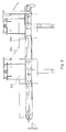
- the hollow waste glass collector (1) shown in FIG. 1 is designed as a depot container (2). On its front side (3) it has an insertion opening behind a projecting insertion tube (4), which is closed with an aperture or a slotted rubber membrane. Under the opening there is a separating device, generally designated (5), which interacts with a color sorting device (not shown).
- the color sorting consists of a light source and a sensor, which separates the light according to the three hollow glass colors white, brown, green and then triggers an electrical signal that actuates a rotary flap that ejects a hollow glass recognized by its color.
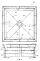
- the container is divided into chambers (7-9), which are combined in one unit.
- This has a square plan in accordance with the exemplary embodiment.
- a chamber partition (10) which is practically half, runs in one diagonal the container of a chamber (7) reserved for white glass.
- two parallel chamber walls (13, 14) run up to the wall (10). They serve for the division of a longitudinal chamber (15), which extends to the middle of the container and for the formation of the two chambers (8 and 9), which accommodate brown and green glass.
- the longitudinal chamber (15) serves to hold non-glass.
- a continuous conveyor (16) is aligned with the diagonal, which the chamber walls (13 and 14) are parallel. It is therefore located above the longitudinal center (17) of the longitudinal chamber (15).
- the continuous conveyor (16) is a conveyor belt (18) which is arranged with its drive roller (19) directly behind the end wall (3) and with its reversers (20) at a distance of the rear end wall (21) of the container ends. Non-glass is thrown into the chamber (15) through the opening (22) between the rear end wall (21) and the reverser (20).
- the continuous conveyor is arranged essentially horizontally.
- a lateral ejection is provided for loading the glasses with the glasses on the continuous conveyor (16).
- swivel flaps operated by the color sorting are shown in the embodiment of FIG. 2 in a top view and in the swiveled-out position next to the conveyor belt at (23-26).
- the swivel flaps are convexly curved in their plane and in the conveying direction, which is represented by the arrow (27). They swing about vertical axes, as shown at (28) for the swivel flap (26), as soon as they are brought into the eject position.
- the ejection position of the swivel flap (24) is drawn in dash-dotted lines.
- each swivel flap There is an ax under each swivel flap, as shown for example at (29) in Fig. 2.
- the hatchet has an upward-facing cutting edge that serves to shatter a hollow glass body that has been deflected by one of the swivel flaps.
- a hollow glass transfer is located under the insertion opening behind the insertion tube (4), which is generally drawn at (30) in FIG. 1. It this is a receiving funnel, which is formed by two longitudinal walls (31, 32), both of which are designed as funnel swings according to FIG. 8.
- a receiving funnel which is formed by two longitudinal walls (31, 32), both of which are designed as funnel swings according to FIG. 8.
- one of the funnel wings (32) is drawn. It sits on a hinge (33) and has an arm (35) loaded with a weight (34) with which it is pretensioned in the closing direction. The arm limits the pivoting movement by hitting stops (36, 37).
- the inner end (38) of the swivel flap (32) closes a slot, the center line (39) of which is drawn and corresponds to the longitudinal center plane (40) of a hollow glass container (41).
- the longitudinal slot (39) is delimited by the other funnel rocker (31).
- the end wall of the funnel is shown at (40a) in Fig. 1 and lies above the funnel walls described. It serves as a baffle when the hollow glass is thrown in through the tube (4), as a result of which the hollow glass container (41) assumes its position on the funnel wings (31, 32) as shown in FIG. 3. Then he presses with his full weight on the rockers (31, 32), which are deflected until the respective arm (35) reaches the stop (37). Then the hollow glass container (41) falls on the Conveyor belt (18). As soon as the hollow glass container has left the funnel, the swing arms close automatically.
- This swinging movement can also be used to switch on the current for the color sorting and the separating device (5). Then the available energy is used sparingly, because the belt only runs when a hollow glass has been inserted.
- the design of the continuous conveyor results in particular from the illustration in FIG. 6.
- the conveyor belt is then divided into a pair of parallel belts (41a, 42a).
- the reverser can be tensioned and pivoted at (43 and 44), so that both belts (41a and 42a) run absolutely parallel over the reversers and the drive roller.
- the two belts (41a and 42a) are supported on a guide in the upper run.
- the guide consists of a tube (46, 47) assigned to each belt (41a, 42a), both tubes being laid in parallel.
- the belts (41a and 42a) normally run in a common plane due to their inherent rigidity. But as soon as the inner belt edges (48, 49) of a hollow glass, they are pressed down, resulting in a trough, which is indicated at (50). For this reason, the hollow glasses are centered in the longitudinal center (51) of the conveyor belt (18). This centering allows the light source of the color sorting to be arranged directly behind the receiving funnel (31, 32).
- the trough (50) is formed outside the tubes by a one-piece belt guide of the upper run (6).
- the pivoting flaps (23-26) which swing about vertical axes (28) steer the hollow glasses (41) into a funnel (52-55).
- These funnels are designed uniformly. They have an obliquely upwardly directed floor, which consists of a pair of inclined walls (56, 57), of which at least one, namely the inclined wall (57), is loaded against a weight (58) Swivel arm (59) can swing down. It then releases a longitudinal slot through which a hollow glass body (55a) falls down. This slot forms an obtuse angle with the conveying direction.
- a locking flap (56a) oriented transversely to the continuous conveyor and its plane is used in order first to stop a hollow body, which then has a double pivoting flap (57c) to move the hollow glass body (55a) transversely to the belt on one of two sides is distracted. In this way, two adjacent chambers or chamber spaces of the depot container can be filled.
- FIG. 7 shows the two swivel flaps (57a, 57b) which form the double flap.
- a bevel (58a, 59a) is arranged under each of the swivel flaps, which further promotes the deflected hollow glass as a dead slide, which is thereby directed onto the ax (29) and smashed.
- the container shown in FIG. 8 shows behind the front end wall (3) the compartment for a battery (60) and the two funnel walls (31, 32), which can be deflected against the action of weights (34, 34a).
- the direction of the fall of the hollow glass containers (41) is shown in dash-dotted lines, which accordingly fall on the cutting edges of the hatchets (29) at a certain distance from their base or neck.
- These hatchets and the described funnels (52, 53) are located above or at the bottom of short recesses (63, 64), which improves the filling of the chambers.
- the vertical outer walls (65-67) of the depot container are provided with outlet funnels, which are drawn at (63a and 64a) in FIG. 8.
- Each chamber has a bottom flap (65a, 66a) which is hinged on its outer edge (68a, 69a) lies, which are biased in the closing direction.
- the inner ends (70, 71) of the bottom flaps (65a, 66a) can be locked with bolts (72, 73) in the closed position.
- an emptying shaft (73a) is drawn, which has a guide funnel with inclined walls (74, 75) at its upper end.
- the shaft is provided with a stationary column (76), the upper end (77) of which can be engaged in a square tube (78) of the container.
- the end (77), which is also designed as a square tube, then deflects the bolts (72 and 73), with the bottom flaps (65a, 66a) being deflected against their springs at the same time.
- the bottom flaps (65a and 66a) can be seen in FIG. 12 and have an outline shaped like an isosceles triangle in the glass chambers.
- the funnel walls are drawn for the bottom flap (66a) at (63a, 79 and 80).
- the bottom flaps (65a, 81 and 82) sit under identical discharge funnels.
- the longer flap edges (83) are on the outside and in the hinges which are described in connection with FIG. 8.
- the hinge at (84) is shown in dash-dot lines.
- the hinge axis (85) is then accommodated in bearing blocks (86) and secured with spring washers (87).
- a helical spring (88) presses on the bottom flap (82), the force of which is so designed that the bottom flap (82) is normally kept closed.
- the bearing blocks (89) which rotate about the axis (85), sit on the bottom flap.
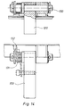
- a cam (91) is attached to the underside (90) of the flap (82) and pivots with the flap (82).
- the cam (91) has an outwardly projecting arm (92) with a rounded head (93). It can be pivoted over the arc (94) up to a stop (95) as soon as the cam (93) hits a carrier (96) which is arranged below the inclined walls (74, 75). The movement of the cam (91) over the bow (94) is forced with the weight of the depot container.
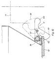
- FIG. 10 The support of the swivel flaps in the apex of their outline can be seen in FIG. 10.
- the bolt (72) shown there can be pivoted against the force of a spring (97) about a fixed axis (98) over the arc (99) as soon as its rounded head (100) is deflected by the square (77) of the column (76) has been. His inner arm (101) then releases the tip (102) of the flap (82), which can therefore swing out.
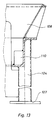
- FIG. 11 and 12 show a transfer device (103) which corresponds to the shaft arrangement (73a) explained in connection with the illustration in FIG. 8. In contrast to this, it rests on four supports (104, 105) which are provided with base plates (106 and 107).
- the transfer device (103) has an overhead centering funnel (108), which is used to engage the depot container. Fixed stop cams (109 to 112) are attached to the funnel walls, which correspond to the stop profiles described in connection with the funnel arrangement of FIG. 8.
- the transfer device (103) also has walls (113-115) which can be aligned with the chamber walls (10 and 11). With the chamber walls (13 and 14) the walls (116, 117) can be aligned because the chamber (15) has only been carried out up to the center of the square tube (78), so that there is a chamber wall in the depot container which can be aligned with the wall (114).
- the chamber (15) has a rectangular bottom flap (118).
- the bottom flap can be pivoted out about a hinge (119), which corresponds to the structure of the hinge (84). It can be triggered with a bolt (120) which is actuated by the column (78).
- the transfer device (103) is set up on the platform (121) of a platform body (122) of a truck (not otherwise shown).
- This platform has partitions (123, and 124 and 125), which the form inner boundaries of compartments (126) for white glass, (127 and 128) for stained glass, and (129) for non-glass.
- the depot container (2) has a high level of dimensional stability. Therefore, in the corners (135, 136) (Fig. 2) handles (137) in recesses of the lid (138) (Fig. 1) can be fastened, with which the container (2) can be lifted with a crane harness without Reinforcements are required in the container.
- the container structure described can therefore also be used for other waste materials.
Landscapes
- Engineering & Computer Science (AREA)
- Mechanical Engineering (AREA)
- Processing Of Solid Wastes (AREA)
- Sorting Of Articles (AREA)
- Treating Waste Gases (AREA)
- Superconductors And Manufacturing Methods Therefor (AREA)
- Control And Other Processes For Unpacking Of Materials (AREA)
- Disintegrating Or Milling (AREA)
- Preparation Of Compounds By Using Micro-Organisms (AREA)
- Medicines Containing Material From Animals Or Micro-Organisms (AREA)
Priority Applications (2)
| Application Number | Priority Date | Filing Date | Title |
|---|---|---|---|
| AT88105833T ATE86534T1 (de) | 1988-03-26 | 1988-04-13 | Abfallhohlglassammler mit vereinzelungsvorrichtung und farbsortierung. |
| JP63231515A JPH01126242A (ja) | 1987-09-18 | 1988-09-17 | 廃棄中空ガラスの収集装置 |
Applications Claiming Priority (2)
| Application Number | Priority Date | Filing Date | Title |
|---|---|---|---|
| DE3810450 | 1988-03-26 | ||
| DE3810450 | 1988-03-26 |
Publications (3)
| Publication Number | Publication Date |
|---|---|
| EP0334987A2 EP0334987A2 (de) | 1989-10-04 |
| EP0334987A3 EP0334987A3 (en) | 1989-11-15 |
| EP0334987B1 true EP0334987B1 (de) | 1993-03-10 |
Family
ID=6350863
Family Applications (1)
| Application Number | Title | Priority Date | Filing Date |
|---|---|---|---|
| EP19880105833 Expired - Lifetime EP0334987B1 (de) | 1987-09-18 | 1988-04-13 | Abfallhohlglassammler mit Vereinzelungsvorrichtung und Farbsortierung |
Country Status (6)
| Country | Link |
|---|---|
| EP (1) | EP0334987B1 (da) |
| AT (1) | ATE86534T1 (da) |
| DE (1) | DE3879184D1 (da) |
| DK (1) | DK138189A (da) |
| FI (1) | FI891412A7 (da) |
| NO (1) | NO891258L (da) |
Cited By (1)
| Publication number | Priority date | Publication date | Assignee | Title |
|---|---|---|---|---|
| CN106005815A (zh) * | 2016-07-28 | 2016-10-12 | 天津聚盛龙庄源科技有限公司 | 一种分类回收垃圾车及其配套垃圾袋 |
Families Citing this family (8)
| Publication number | Priority date | Publication date | Assignee | Title |
|---|---|---|---|---|
| DE4018424A1 (de) * | 1990-06-08 | 1991-12-12 | Mabeg Abfall & Entsorgung | Anordnung zum verladen von nach farben sortierten hohlglaesern |
| DE4235851A1 (de) * | 1992-10-23 | 1994-04-28 | Schaefer Gmbh Fritz | Klappbehälter mit mehreren Kammern |
| BE1008100A5 (fr) * | 1994-04-01 | 1996-01-16 | D V T | Procede et dispositif de recolte selective d'objets en verre et de stockage temporaire de leur matiere. |
| FR2737982B1 (fr) * | 1995-08-23 | 1998-12-31 | Boudet Daniel | Dispositif de tri de recipients, notamment de bouteilles, selon leur poids et leur dimension |
| GB9610211D0 (en) * | 1996-05-16 | 1996-07-24 | Post Office | Device for opening a container |
| DE10249932A1 (de) * | 2002-10-22 | 2004-05-13 | Technische Fachhochschule Wildau | Verfahren und Vorrichtung zur selektiven Sammlung von Objekten aus Glas und zu deren zeitweisen Aufbewahrung |
| CN106005814A (zh) * | 2016-07-18 | 2016-10-12 | 泰州市蓝海环保科技有限公司 | 一种智能分类垃圾箱 |
| CN115090559B (zh) * | 2022-08-26 | 2022-11-11 | 启东市云鹏玻璃机械有限公司 | 一种基于图像处理的玻璃瓶回收除杂方法及系统 |
Citations (2)
| Publication number | Priority date | Publication date | Assignee | Title |
|---|---|---|---|---|
| US3747755A (en) * | 1971-12-27 | 1973-07-24 | Massachusetts Inst Technology | Apparatus for determining diffuse and specular reflections of infrared radiation from a sample to classify that sample |
| DE2952411B1 (de) * | 1979-12-27 | 1981-05-27 | Erkelenzer Maschinenfabrik Ferd.Clasen KG, 5140 Erkelenz | Vorrichtung zum getrennten Sammeln von Glasbruch verschiedener Faerbung |
Family Cites Families (3)
| Publication number | Priority date | Publication date | Assignee | Title |
|---|---|---|---|---|
| US3312357A (en) * | 1965-03-02 | 1967-04-04 | Honeggers & Co Inc | Method and apparatus for loading pallets |
| US4205752A (en) * | 1977-07-13 | 1980-06-03 | Tri/Valley Growers | Color sorting of produce |
| DE8436466U1 (de) * | 1984-12-13 | 1987-05-07 | MAB Marlis Kellermann, 7521 Dettenheim | Glas-Sortieranlage |
-
1988
- 1988-04-13 DE DE8888105833T patent/DE3879184D1/de not_active Expired - Fee Related
- 1988-04-13 EP EP19880105833 patent/EP0334987B1/de not_active Expired - Lifetime
- 1988-04-13 AT AT88105833T patent/ATE86534T1/de not_active IP Right Cessation
-
1989
- 1989-03-21 DK DK138189A patent/DK138189A/da not_active Application Discontinuation
- 1989-03-22 NO NO89891258A patent/NO891258L/no unknown
- 1989-03-23 FI FI891412A patent/FI891412A7/fi not_active IP Right Cessation
Patent Citations (2)
| Publication number | Priority date | Publication date | Assignee | Title |
|---|---|---|---|---|
| US3747755A (en) * | 1971-12-27 | 1973-07-24 | Massachusetts Inst Technology | Apparatus for determining diffuse and specular reflections of infrared radiation from a sample to classify that sample |
| DE2952411B1 (de) * | 1979-12-27 | 1981-05-27 | Erkelenzer Maschinenfabrik Ferd.Clasen KG, 5140 Erkelenz | Vorrichtung zum getrennten Sammeln von Glasbruch verschiedener Faerbung |
Cited By (1)
| Publication number | Priority date | Publication date | Assignee | Title |
|---|---|---|---|---|
| CN106005815A (zh) * | 2016-07-28 | 2016-10-12 | 天津聚盛龙庄源科技有限公司 | 一种分类回收垃圾车及其配套垃圾袋 |
Also Published As
| Publication number | Publication date |
|---|---|
| DK138189A (da) | 1989-09-27 |
| NO891258L (no) | 1989-09-27 |
| ATE86534T1 (de) | 1993-03-15 |
| EP0334987A3 (en) | 1989-11-15 |
| DK138189D0 (da) | 1989-03-21 |
| DE3879184D1 (de) | 1993-04-15 |
| FI891412A0 (fi) | 1989-03-23 |
| FI891412A7 (fi) | 1989-09-27 |
| EP0334987A2 (de) | 1989-10-04 |
| NO891258D0 (no) | 1989-03-22 |
Similar Documents
| Publication | Publication Date | Title |
|---|---|---|
| DE3537546C2 (da) | ||
| DE2558433C3 (de) | Müllsammei- und Transportsystem | |
| DE3703557C2 (de) | Schüttung an einem Müllfahrzeug | |
| EP0334987B1 (de) | Abfallhohlglassammler mit Vereinzelungsvorrichtung und Farbsortierung | |
| EP0759880B1 (de) | Müllsammel- und transportsystem | |
| DE4121442C2 (de) | Müllsammel- und Transportsystem | |
| EP0356833B1 (de) | Schüttung | |
| DE2838580A1 (de) | Verfahren zum verpacken von verformbaren produkten, z.b. biegsamen beuteln, in behaeltern und vorrichtung zur durchfuehrung dieses verfahrens | |
| DE69324669T2 (de) | Hüllfahrzeug mit seitlich angebrachter ladevorrichtung | |
| DE4018424C2 (da) | ||
| EP0220483A2 (de) | Müllsammelsystem | |
| DE8706418U1 (de) | Müllfahrzeug | |
| DE19717008C2 (de) | Glasrecyclingsystem | |
| EP2253564A1 (de) | Sammelbehälter für zu sammelnde Güter | |
| DE69825489T2 (de) | Fahrzeug zur getrennten aufnahme von abfall | |
| DE3640132A1 (de) | Muellfahrzeugaufbau | |
| DE69505510T2 (de) | Verfahren und vorrichtung zur selektiven sammlung von gegenständen aus glas und zum zeitweiligen lagern ihres stoffes | |
| DE202021002352U1 (de) | System zum Speichern von recycelbaren Behältern | |
| EP0060966A1 (de) | Müllsammel- und Transportsystem | |
| DE3619949C1 (en) | Impact roller crusher | |
| DE3612965A1 (de) | Muellbehaelter | |
| DE3447155A1 (de) | Vorrichtung zur beseitigung von hausmuell | |
| EP0505354B1 (de) | Abfallsammelbehälter | |
| DE4001717A1 (de) | Verfahren zur recyclingfaehig sortierten hausmuellentsorgung | |
| DE8505883U1 (de) | Abfall-Sammelbehälter |
Legal Events
| Date | Code | Title | Description |
|---|---|---|---|
| PUAI | Public reference made under article 153(3) epc to a published international application that has entered the european phase |
Free format text: ORIGINAL CODE: 0009012 |
|
| PUAL | Search report despatched |
Free format text: ORIGINAL CODE: 0009013 |
|
| AK | Designated contracting states |
Kind code of ref document: A2 Designated state(s): AT BE CH DE ES FR GB GR IT LI LU NL SE |
|
| AK | Designated contracting states |
Kind code of ref document: A3 Designated state(s): AT BE CH DE ES FR GB GR IT LI LU NL SE |
|
| 17P | Request for examination filed |
Effective date: 19891124 |
|
| 17Q | First examination report despatched |
Effective date: 19920226 |
|
| GRAA | (expected) grant |
Free format text: ORIGINAL CODE: 0009210 |
|
| AK | Designated contracting states |
Kind code of ref document: B1 Designated state(s): AT BE CH DE ES FR GB GR IT LI LU NL SE |
|
| PG25 | Lapsed in a contracting state [announced via postgrant information from national office to epo] |
Ref country code: ES Free format text: THE PATENT HAS BEEN ANNULLED BY A DECISION OF A NATIONAL AUTHORITY Effective date: 19930310 Ref country code: BE Effective date: 19930310 Ref country code: NL Effective date: 19930310 Ref country code: FR Effective date: 19930310 Ref country code: GB Effective date: 19930310 Ref country code: GR Free format text: LAPSE BECAUSE OF FAILURE TO SUBMIT A TRANSLATION OF THE DESCRIPTION OR TO PAY THE FEE WITHIN THE PRESCRIBED TIME-LIMIT Effective date: 19930310 Ref country code: SE Effective date: 19930310 Ref country code: IT Free format text: LAPSE BECAUSE OF FAILURE TO SUBMIT A TRANSLATION OF THE DESCRIPTION OR TO PAY THE FEE WITHIN THE PRESCRIBED TIME-LIMIT;WARNING: LAPSES OF ITALIAN PATENTS WITH EFFECTIVE DATE BEFORE 2007 MAY HAVE OCCURRED AT ANY TIME BEFORE 2007. THE CORRECT EFFECTIVE DATE MAY BE DIFFERENT FROM THE ONE RECORDED. Effective date: 19930310 |
|
| REF | Corresponds to: |
Ref document number: 86534 Country of ref document: AT Date of ref document: 19930315 Kind code of ref document: T |
|
| PG25 | Lapsed in a contracting state [announced via postgrant information from national office to epo] |
Ref country code: AT Effective date: 19930413 |
|
| REF | Corresponds to: |
Ref document number: 3879184 Country of ref document: DE Date of ref document: 19930415 |
|
| PG25 | Lapsed in a contracting state [announced via postgrant information from national office to epo] |
Ref country code: LU Free format text: LAPSE BECAUSE OF NON-PAYMENT OF DUE FEES Effective date: 19930430 Ref country code: LI Effective date: 19930430 Ref country code: CH Effective date: 19930430 |
|
| EN | Fr: translation not filed | ||
| NLV1 | Nl: lapsed or annulled due to failure to fulfill the requirements of art. 29p and 29m of the patents act | ||
| GBV | Gb: ep patent (uk) treated as always having been void in accordance with gb section 77(7)/1977 [no translation filed] |
Effective date: 19930310 |
|
| REG | Reference to a national code |
Ref country code: CH Ref legal event code: PL |
|
| PG25 | Lapsed in a contracting state [announced via postgrant information from national office to epo] |
Ref country code: DE Effective date: 19940101 |
|
| PLBE | No opposition filed within time limit |
Free format text: ORIGINAL CODE: 0009261 |
|
| STAA | Information on the status of an ep patent application or granted ep patent |
Free format text: STATUS: NO OPPOSITION FILED WITHIN TIME LIMIT |
|
| 26N | No opposition filed |