EP0334401A2 - Méthode et dispositif pour contrôler l'entrée d'un médium dans un espace de fuite - Google Patents
Méthode et dispositif pour contrôler l'entrée d'un médium dans un espace de fuite Download PDFInfo
- Publication number
- EP0334401A2 EP0334401A2 EP19890200232 EP89200232A EP0334401A2 EP 0334401 A2 EP0334401 A2 EP 0334401A2 EP 19890200232 EP19890200232 EP 19890200232 EP 89200232 A EP89200232 A EP 89200232A EP 0334401 A2 EP0334401 A2 EP 0334401A2
- Authority
- EP
- European Patent Office
- Prior art keywords
- valve
- valve device
- closing member
- closing
- leakage
- Prior art date
- Legal status (The legal status is an assumption and is not a legal conclusion. Google has not performed a legal analysis and makes no representation as to the accuracy of the status listed.)
- Pending
Links
- 238000000034 method Methods 0.000 title claims abstract description 10
- 238000006467 substitution reaction Methods 0.000 claims abstract 3
- 238000007789 sealing Methods 0.000 claims description 19
- 238000010276 construction Methods 0.000 abstract 1
- 238000010327 methods by industry Methods 0.000 abstract 1
- 238000004140 cleaning Methods 0.000 description 6
- 239000012459 cleaning agent Substances 0.000 description 4
- 239000007788 liquid Substances 0.000 description 3
- 239000012530 fluid Substances 0.000 description 2
- 230000003993 interaction Effects 0.000 description 2
- 230000035515 penetration Effects 0.000 description 2
- 239000000256 polyoxyethylene sorbitan monolaurate Substances 0.000 description 2
- 235000013361 beverage Nutrition 0.000 description 1
- 230000002950 deficient Effects 0.000 description 1
- 239000003599 detergent Substances 0.000 description 1
- 230000018109 developmental process Effects 0.000 description 1
- 238000006073 displacement reaction Methods 0.000 description 1
- 230000002349 favourable effect Effects 0.000 description 1
- 230000012447 hatching Effects 0.000 description 1
- 238000009434 installation Methods 0.000 description 1
- 239000000203 mixture Substances 0.000 description 1
- 230000001954 sterilising effect Effects 0.000 description 1
Images


Classifications
-
- F—MECHANICAL ENGINEERING; LIGHTING; HEATING; WEAPONS; BLASTING
- F16—ENGINEERING ELEMENTS AND UNITS; GENERAL MEASURES FOR PRODUCING AND MAINTAINING EFFECTIVE FUNCTIONING OF MACHINES OR INSTALLATIONS; THERMAL INSULATION IN GENERAL
- F16K—VALVES; TAPS; COCKS; ACTUATING-FLOATS; DEVICES FOR VENTING OR AERATING
- F16K11/00—Multiple-way valves, e.g. mixing valves; Pipe fittings incorporating such valves
- F16K11/02—Multiple-way valves, e.g. mixing valves; Pipe fittings incorporating such valves with all movable sealing faces moving as one unit
- F16K11/06—Multiple-way valves, e.g. mixing valves; Pipe fittings incorporating such valves with all movable sealing faces moving as one unit comprising only sliding valves, i.e. sliding closure elements
- F16K11/065—Multiple-way valves, e.g. mixing valves; Pipe fittings incorporating such valves with all movable sealing faces moving as one unit comprising only sliding valves, i.e. sliding closure elements with linearly sliding closure members
- F16K11/07—Multiple-way valves, e.g. mixing valves; Pipe fittings incorporating such valves with all movable sealing faces moving as one unit comprising only sliding valves, i.e. sliding closure elements with linearly sliding closure members with cylindrical slides
-
- F—MECHANICAL ENGINEERING; LIGHTING; HEATING; WEAPONS; BLASTING
- F16—ENGINEERING ELEMENTS AND UNITS; GENERAL MEASURES FOR PRODUCING AND MAINTAINING EFFECTIVE FUNCTIONING OF MACHINES OR INSTALLATIONS; THERMAL INSULATION IN GENERAL
- F16K—VALVES; TAPS; COCKS; ACTUATING-FLOATS; DEVICES FOR VENTING OR AERATING
- F16K3/00—Gate valves or sliding valves, i.e. cut-off apparatus with closing members having a sliding movement along the seat for opening and closing
- F16K3/22—Gate valves or sliding valves, i.e. cut-off apparatus with closing members having a sliding movement along the seat for opening and closing with sealing faces shaped as surfaces of solids of revolution
- F16K3/24—Gate valves or sliding valves, i.e. cut-off apparatus with closing members having a sliding movement along the seat for opening and closing with sealing faces shaped as surfaces of solids of revolution with cylindrical valve members
- F16K3/243—Packings
-
- F—MECHANICAL ENGINEERING; LIGHTING; HEATING; WEAPONS; BLASTING
- F16—ENGINEERING ELEMENTS AND UNITS; GENERAL MEASURES FOR PRODUCING AND MAINTAINING EFFECTIVE FUNCTIONING OF MACHINES OR INSTALLATIONS; THERMAL INSULATION IN GENERAL
- F16K—VALVES; TAPS; COCKS; ACTUATING-FLOATS; DEVICES FOR VENTING OR AERATING
- F16K25/00—Details relating to contact between valve members and seats
-
- Y—GENERAL TAGGING OF NEW TECHNOLOGICAL DEVELOPMENTS; GENERAL TAGGING OF CROSS-SECTIONAL TECHNOLOGIES SPANNING OVER SEVERAL SECTIONS OF THE IPC; TECHNICAL SUBJECTS COVERED BY FORMER USPC CROSS-REFERENCE ART COLLECTIONS [XRACs] AND DIGESTS
- Y10—TECHNICAL SUBJECTS COVERED BY FORMER USPC
- Y10S—TECHNICAL SUBJECTS COVERED BY FORMER USPC CROSS-REFERENCE ART COLLECTIONS [XRACs] AND DIGESTS
- Y10S251/00—Valves and valve actuation
- Y10S251/90—Valves with o-rings
-
- Y—GENERAL TAGGING OF NEW TECHNOLOGICAL DEVELOPMENTS; GENERAL TAGGING OF CROSS-SECTIONAL TECHNOLOGIES SPANNING OVER SEVERAL SECTIONS OF THE IPC; TECHNICAL SUBJECTS COVERED BY FORMER USPC CROSS-REFERENCE ART COLLECTIONS [XRACs] AND DIGESTS
- Y10—TECHNICAL SUBJECTS COVERED BY FORMER USPC
- Y10T—TECHNICAL SUBJECTS COVERED BY FORMER US CLASSIFICATION
- Y10T137/00—Fluid handling
- Y10T137/0318—Processes
-
- Y—GENERAL TAGGING OF NEW TECHNOLOGICAL DEVELOPMENTS; GENERAL TAGGING OF CROSS-SECTIONAL TECHNOLOGIES SPANNING OVER SEVERAL SECTIONS OF THE IPC; TECHNICAL SUBJECTS COVERED BY FORMER USPC CROSS-REFERENCE ART COLLECTIONS [XRACs] AND DIGESTS
- Y10—TECHNICAL SUBJECTS COVERED BY FORMER USPC
- Y10T—TECHNICAL SUBJECTS COVERED BY FORMER US CLASSIFICATION
- Y10T137/00—Fluid handling
- Y10T137/5762—With leakage or drip collecting
-
- Y—GENERAL TAGGING OF NEW TECHNOLOGICAL DEVELOPMENTS; GENERAL TAGGING OF CROSS-SECTIONAL TECHNOLOGIES SPANNING OVER SEVERAL SECTIONS OF THE IPC; TECHNICAL SUBJECTS COVERED BY FORMER USPC CROSS-REFERENCE ART COLLECTIONS [XRACs] AND DIGESTS
- Y10—TECHNICAL SUBJECTS COVERED BY FORMER USPC
- Y10T—TECHNICAL SUBJECTS COVERED BY FORMER US CLASSIFICATION
- Y10T137/00—Fluid handling
- Y10T137/8593—Systems
- Y10T137/86493—Multi-way valve unit
- Y10T137/86879—Reciprocating valve unit
-
- Y—GENERAL TAGGING OF NEW TECHNOLOGICAL DEVELOPMENTS; GENERAL TAGGING OF CROSS-SECTIONAL TECHNOLOGIES SPANNING OVER SEVERAL SECTIONS OF THE IPC; TECHNICAL SUBJECTS COVERED BY FORMER USPC CROSS-REFERENCE ART COLLECTIONS [XRACs] AND DIGESTS
- Y10—TECHNICAL SUBJECTS COVERED BY FORMER USPC
- Y10T—TECHNICAL SUBJECTS COVERED BY FORMER US CLASSIFICATION
- Y10T137/00—Fluid handling
- Y10T137/8593—Systems
- Y10T137/86919—Sequentially closing and opening alternately seating flow controllers
-
- Y—GENERAL TAGGING OF NEW TECHNOLOGICAL DEVELOPMENTS; GENERAL TAGGING OF CROSS-SECTIONAL TECHNOLOGIES SPANNING OVER SEVERAL SECTIONS OF THE IPC; TECHNICAL SUBJECTS COVERED BY FORMER USPC CROSS-REFERENCE ART COLLECTIONS [XRACs] AND DIGESTS
- Y10—TECHNICAL SUBJECTS COVERED BY FORMER USPC
- Y10T—TECHNICAL SUBJECTS COVERED BY FORMER US CLASSIFICATION
- Y10T137/00—Fluid handling
- Y10T137/8593—Systems
- Y10T137/87917—Flow path with serial valves and/or closures
- Y10T137/87981—Common actuator
- Y10T137/87997—Alternately seating
Definitions
- the invention relates to a method for controlling the medium entry into at least one leakage space of a valve device according to the preamble of claim 1 and a device for its implementation.
- patent application P 37 01 027.1 describes a valve with a leakage space which is equipped with two sealing points which are arranged in series and in the closed position of the valve prevent the overflow of fluids from one valve housing part into another.
- the leakage space is arranged between the sealing points and connected to the surroundings of the valve via the valve housing.
- a closure part is provided, which is arranged to be movable relative to the closing member in the direction of its degree of freedom of movement and controls the connection between the leakage space and the interior of the valve housing parts.
- the closure part is in permanent contact with the two sealing points, these being through the valve housing side or sealing means arranged on the closing member or closure part side.
- the invention has for its object to provide a method for controlling the medium entry into at least one leakage space of a valve device, the valve device having more than two valve housing parts with inlet and outlet housing parts and in particular with controllable connections between the leakage space and the interior of the valve housing is formed.
- the object is achieved by applying the characterizing features of claim 1 or 2, the method according to the invention equipping the valve device with switching functions and properties which are new and advantageous.
- valve device for performing the aforementioned method are described in subclaims 3 to 12. It can be seen that a valve device is proposed which is so far unknown in its structure.
- the middle valve housing part can either be closed on both sides or open on both sides with respect to the outer valve housing parts.
- the middle valve housing part In the other two positions B and C, there is a switchover function between the middle and the respectively switched outer valve housing part.
- the connection of the middle valve housing part and the outer valve housing parts is identified according to the known nomenclature with 1, 2 and 4, while two further connections are labeled 3 and 5.
- the table below shows the switching status of the respective connections 1 to 5 in positions A, B and C.
- a closed connection is marked with "0", an open connection with "1".
- connections 3 and 5 each represent the connection of the leakage space to the interior of the valve housing. According to the invention, this connection is now always closed, both in the closed and in the open position of the valve.
- the following table shows the switching states of the object according to the invention based on the nomenclature known from pneumatics.
- connection 1 remains closed and the connections 2 and 3 or 4 and 5 are connected to one another, the object according to the invention results in a connection of the connections 1, 2 and 4 to one another, while the Connections of leakage rooms 3 and 5 are in the closed position as intended.
- valve device proposed according to the invention represents a 5/3-way valve which does not exist in this configuration and with the properties mentioned above in the valve area, in particular in the area of the food and beverage industry.
- the valve In addition to the function as a changeover valve, there is a basic position in which the valve is either closed or open. In addition, the valve is leak-proof in every seating area.
- both leakage spaces or one of the two leakage spaces can also be dispensed with, as is provided by an embodiment.
- the closure part replaces the closing member with regard to its interaction with the seal.
- valve device proposed according to the invention which can be easily converted into a so-called 5/2-way valve if the closing member is dimensioned appropriately and the basic position is dispensed with, results in a solution when the problem underlying the aforementioned publication DE-PS 20 27 792 is used. where the lower valve seat is also leak-proof.
- the length of the closing element allows the valve device according to the invention to be used, in contrast to the known valve to design a real 5/2-way valve, since dimensioning is readily possible such that the closing element on the one hand assumes a closed position before it gives up the closed position on the other hand.
- an intermediate position must be taken into account in the circuit passage, in which the middle valve housing part 3 is connected to the two outer valve housings 2 and 4 at the same time.
- the closure part or the closure parts can be arranged between the two closing members.
- a closure part is located on either side of a single closing element.
- both the closing members and the closure parts can be connected to one another, so that with unrestricted function of the valve device, only two drive movements are required from the outside.
- the same advantages result with regard to the design of the drive of such a valve device.
- valve device enables unrestricted, leak-free switching
- valve device according to a further embodiment of the valve device according to the invention there is the possibility of switching the valve with only a single drive movement, but without the leak-free switching, i. H. if a limited switching leakage is accepted. This is achieved in that the closure parts are firmly connected to the closing member at a distance.
- a further embodiment of the valve device according to the invention in the case of closure parts arranged on the inside between the closure members, proposes the combination thereof to form a closure part unit, the latter being displaced relative to the closure member via a rod, the passage of which through the closure member in a simple manner and under favorable conditions by a Bellows can be bridged cohesively.
- valve device provides that the axial extent of the closing member is changed by means of telescopic arrangements, the distance between the closing members being bridged by an elastic connecting element.
- This measure makes it possible to equip the valve device with an ambivalent basic position, namely the basic position "closed” or the basic position "open".
- the largest axial extent of the closing member is to be dimensioned in the basic position of the valve so that the closing member covers both seat areas, including the entire leakage space.
- valve device In its shortest axial extent, the valve device is open on both sides in its basic position from the central valve housing part.
- valve device according to the invention when, for example, a tank outlet is connected to the middle housing part and the outer valve housing parts are connected with lines. While in conventional arrangements of multi-way switch valves all areas of the multi-way switch valve arrangement coming into contact with the product were only detected when either both lines or at least the more distant line from the tank was subjected to cleaning agent, all areas of the valve device proposed according to the invention are already detected when cleaning one of the two lines from the tank.
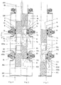
- FIG. 1 shows a valve device with a closure part 5 arranged on the inside between the two closing members 4 and 400.
- the valve device with the three housing parts 100, 200 and 300 is in its basic position A, in which it is closed on both sides by the central valve housing part 200.
- FIGS. 2 and 3 show the two open positions B and C of the valve devices, the upper closing element being in its open position in FIG. 2 and the closure part 5 replacing the bearing it has assumed in the closed position with respect to the seals 70 and 71.
- the underlying closing member 400 is dimensioned such that it has not yet left the underlying seating area with the seals 701 and 711 in the switching position shown.
- the underlying closing member 400 is in its open position, the only closure member 5 has substituted the position of the closing member in its closed position with respect to the seals 701 and 711.
- the upper closing member 4, in the same way as the one below, is dimensioned such that the valve housing parts 100 and 200 are still closed against one another.
- the seals 70 and 71 or 701 and 711 are bounded either by the closing member 4 or 400 or by the closure part 5.
- the leakage space 6 is located between the seals 70 and 71 and the leakage space 61 between the seals 701 and 711.
- the type of hatching indicates in FIGS.
- the closing members 4 and 400 are equally spaced from one another in each of the switching states shown have, so that a connection of both and an actuation is possible via a single rod, not shown, brought up from outside the valve device.
- the closure part 5 requires its own drive, the required switching stroke is smaller than that for the closing members.
- the closure part 5 With its passage opening 5c, the flow V can pass from the middle housing part 200 to the upper housing part 100 or vice versa.
- valve housing parts 100 and 200 In the position of the closure part 5 shown in FIG. 3, the corresponding passage flow through the passage opening 5c is identified by V1.
- the structure and function of the other components in the area of valve housing parts 100 and 200 are known from patent application P 37 01 027.1 and from the Euro-PCT application WO 88/05512 which claims the priority of this patent application.
- This relates in particular to a housing closure part 3, a housing seal 12 and a connecting means 13, a first and a second sealing point 8 and 9, a connection opening 15, a channel 16 and a collecting channel 18, an outlet opening 2a, from which the cleaning liquid designated II or the leak escapes.
- the entry of the cleaning liquid through the connection opening 15 is denoted by I.
- the seating area provided between the valve housing parts 200 and 300 is completely identical to that between the valve housing parts 100 and 200. Parts in this seating area, unlike identical parts in the upper seating area, were defined with regard to their identification by adding number 1 to the names known from the aforementioned patent applications (P37 01 027.1; WO 88/05512). A description of the known arrangement in the lower region of the valve device is therefore unnecessary.
- valve device shown in FIGS. 1 to 3 does not simply represent an addition of two valves known per se from the aforementioned patent applications. Apart from the fact that the combination alone of the two known valves forms a completely new valve device, as already explained above, the main difference compared to the mere combination is that a single closure part 5 and coupled locking members 4 and 400 are provided, which makes the complex valve device with only two mutually different drive movements, which are generated by means not shown, comes out.
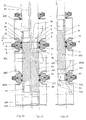
- FIGS. 4 to 6 show another embodiment of the device according to the invention in the three possible switching states, the latter corresponding to those of FIGS. 1 to 3.
- the valve housing parts 100, 200 and 300 and the associated components are identical to those according to FIGS. 1 to 3.
- a complete designation was therefore omitted in these and the following figures.
- Parts 4 and 400, 6 and 61, 8 and 81, 9 and 91, 70 and 701, 71 and 711 are still identified in detail, but do not need, since they have already been explained in the description of FIGS. 1 to 3 be mentioned again with regard to their meaning.
- a second closure part 51 is provided in addition to the closure part 5.
- the closure part 5 is connected, for example, via a connecting web 4c and the closure part 51 with a connecting web 400c to the respectively associated closing member 4 or 400 at a distance s1. Since the upper closing element 4 is in turn firmly connected to the lower closing element 400 via a rod 400a, the valve device shown can be switched by a single drive movement which is generated by means not shown. The switching movement from the closing However, there is no leakage-free movement into the respective open position, since the aforementioned distance s1 is provided between the closure part and the closing element 5, 51 or 4, 400.
- the connecting webs 4c and 400c have the task of fixing the respectively assigned seals 70, 71 and 701, 711 in their required position during the switching movement from the closed to the open position or vice versa.
- the throughflow designated V passes from the valve housing part 200 via the passage opening 5c and the openings 4b into the upper valve housing part 100.
- the throughflow designated V1 is correspondingly passed via a Passage opening 51c and openings 400b, which are formed between the connecting webs 400c, from the central valve housing part 200 into the lower valve housing part 300 or vice versa.
- the dash-dotted lines 21 and 211 indicate possible compensation pistons with which the valve device can be provided and which ensure a complete pressure compensation at the closing element 4, 400.
- the two closing members 4 and 400 are connected to one another via at least one eccentrically arranged second connecting part 53.
- the upper closing element 4, and thus also the lower closing element 400, is driven via a rod 4a designed as a hollow rod.
- a rod 5a guided In this hollow rod is a rod 5a guided, which is connected to a closure part unit 500.
- the closure part unit 500 consists of the two closure parts 5 and 51, which in turn are firmly connected to one another via a first connecting part 52.
- the closure part unit 500 is arranged so as to be movable relative to the closing members 4, 400 and can be displaced a total of two times the distance s2.
- This double distance s2 approximately results in an opening cross-section corresponding to the nominal cross-section of the valve device, the latter being formed in the open positions of the valve between the closure part 5 or 51 and the respectively associated closing member 4 or 400.
- second passage openings 54 are provided between the first connecting parts 52, via which the above-mentioned passage flows V and V1 from the closure part unit 500 in the surrounding valve housing part 200 or vice versa can pass through.
- the illustrated embodiment realizes completely leak-free switching processes of the valve device. For this purpose, two mutually independent drive movements of the rods 4a and 5a are required, which are controlled by means not shown.
- FIGS. 4 to 6 show a further embodiment of the valve device according to the invention.
- the closure parts 5 and 51 are in firm connection with respect to the closing member 401, which is combined in a single component and now carries the closure parts 5 on the outside via the connecting web 4c and the closure part 51 via the connecting web 400c.
- the distance between the closure part 5 or 51 and the closing member 401 is again s1.
- the rest of the structure of the valve device and its mode of operation is otherwise completely identical to that according to FIGS. 4 to 6. A further description and explanation is therefore unnecessary.
- FIGS. 13 to 15 can be explained in terms of its basic structure by the direct comparison with the embodiment according to FIGS. 10 to 12 and with regard to the function and mode of operation of its closure parts 5 and 51 by comparison with the embodiment according to FIGS. 7 to 9
- the single closing member 401 is now driven via at least one eccentrically arranged rod 4a.
- the closure parts 5 and 51 are connected to each other via a rod 5a, which is controlled by means not shown.
- Each closure part 5 or 51 is connected to this rod via a web 5b or 51b.
- the closure parts 5 and 51, the rod 5a and the webs 5b and 51b together form a closure part unit 501 which is displaced relative to the closing member 401 in a relatively movable manner.
- the required displacement is a total of two times the distance s2, which in the open position approximately forms an opening cross section corresponding to the nominal cross section of the valve device.
- An unspecified upper and lower The point of penetration between the rod 5a and the closing member 401 is bridged in a materially integral manner via a bellows 26 or 261.
- these bellows 26, 261 In the basic position of the valve device (FIG. 13), these bellows 26, 261 have their tension-free installation position, while in the open positions of the valve device they are alternately stretched (26 in FIG. 14 and 261 in FIG. 15) or compressed (261 in FIGS. 14 and 26 in Figure 15) are.
- valve device shown in FIGS. 1 to 15 can be made using the features for seals known from the aforementioned patent applications P 3701027.1 and WO 88/05512. Leakage cavities, closure parts and closing members and associated control parts can be realized.
- FIG. 16 and 17 show an embodiment of the valve device in which the closing element 4, 400 (FIG. 16) or the closing element 401 (FIG. 17) changes in its axial extent by means of telescopically operating arrangements 404, 408 or 405, 409 becomes.
- a telescopic rod is drawn at 404 and a first guide bore at 408.
- these components have the designation 405 and 409.
- the distance between the locking members 4 and 400 (FIG. 16) or between the first and the second locking member parts 402 and 403 (FIG. 17) is bridged by an elastic connecting element 406 and 407.
Landscapes
- Engineering & Computer Science (AREA)
- General Engineering & Computer Science (AREA)
- Mechanical Engineering (AREA)
- Multiple-Way Valves (AREA)
- Lift Valve (AREA)
- Taps Or Cocks (AREA)
- Sliding Valves (AREA)
- Valve Housings (AREA)
Applications Claiming Priority (2)
| Application Number | Priority Date | Filing Date | Title |
|---|---|---|---|
| DE19883801569 DE3801569A1 (de) | 1988-01-20 | 1988-01-20 | Verfahren und vorrichtung zur realisierung eines ventilsitzes mit einer gehaeuseseitig angeordneten dichtung |
| DE3801569 | 1988-01-20 |
Publications (2)
| Publication Number | Publication Date |
|---|---|
| EP0334401A2 true EP0334401A2 (fr) | 1989-09-27 |
| EP0334401A3 EP0334401A3 (fr) | 1991-10-02 |
Family
ID=6345638
Family Applications (2)
| Application Number | Title | Priority Date | Filing Date |
|---|---|---|---|
| EP19890200232 Pending EP0334401A3 (fr) | 1988-01-20 | 1989-01-17 | Méthode et dispositif pour contrôler l'entrée d'un médium dans un espace de fuite |
| EP19890901949 Expired - Lifetime EP0378589B1 (fr) | 1988-01-20 | 1989-01-17 | Dispositif de soupape |
Family Applications After (1)
| Application Number | Title | Priority Date | Filing Date |
|---|---|---|---|
| EP19890901949 Expired - Lifetime EP0378589B1 (fr) | 1988-01-20 | 1989-01-17 | Dispositif de soupape |
Country Status (9)
| Country | Link |
|---|---|
| US (1) | US4995416A (fr) |
| EP (2) | EP0334401A3 (fr) |
| JP (1) | JPH02501158A (fr) |
| KR (1) | KR900700810A (fr) |
| BR (1) | BR8904882A (fr) |
| DE (2) | DE3835363C2 (fr) |
| DK (1) | DK456589D0 (fr) |
| FI (1) | FI894439A (fr) |
| WO (1) | WO1989006764A2 (fr) |
Families Citing this family (10)
| Publication number | Priority date | Publication date | Assignee | Title |
|---|---|---|---|---|
| DE4118874C2 (de) * | 1991-06-07 | 1995-02-16 | Tuchenhagen Otto Gmbh | Verfahren zur Reinigung eines leckagefrei schaltenden Doppelsitzventils und Ventilvorrichtung zum Durchführen des Verfahrens |
| DE4233592C2 (de) * | 1992-10-06 | 1997-07-03 | Theo Beurskens | Ventil, insbesondere für eine Heißdampf-Umformation |
| US6131612A (en) * | 1994-11-18 | 2000-10-17 | Beurskens; Theo | Valve for a superheated-steam conversion plant |
| US6065736A (en) * | 1996-10-15 | 2000-05-23 | Hunt; Kevin F. | Ball valve having a non-integral upstream seat and at least one integral downstream seat |
| DE59710144D1 (de) * | 1997-03-18 | 2003-06-26 | Tuchenhagen Gmbh | Sitzreinigungsfähiges doppelsitzventil |
| DE19720566C1 (de) * | 1997-05-16 | 1999-02-11 | Apv Rosista Gmbh | Doppelsitzventil |
| DE19842922A1 (de) * | 1998-09-18 | 2000-03-23 | Rieger Gmbh & Co Kg Geb | Ventil, insbesondere Doppelsitzventil |
| FR2791753B1 (fr) * | 1999-04-02 | 2001-09-21 | Defontaine | Vanne a clapet perfectionne a joint en elastomere |
| DE102012215530A1 (de) * | 2012-08-31 | 2014-03-06 | Krones Ag | Misch-Regelventil |
| DE102016104921A1 (de) * | 2016-03-16 | 2017-09-21 | Endress+Hauser Conducta Gmbh+Co. Kg | Wechselarmatur |
Citations (9)
| Publication number | Priority date | Publication date | Assignee | Title |
|---|---|---|---|---|
| FR889480A (fr) * | 1941-12-30 | 1944-01-11 | V Marzocchi & C Ing | Tiroir de distribution destiné à commander l'arrivée et la sortie d'un fluide |
| US2659568A (en) * | 1948-05-15 | 1953-11-17 | Grove Regulator Company | Valve construction |
| US3283783A (en) * | 1963-10-25 | 1966-11-08 | Clary Corp | Multi-way valve |
| US3643700A (en) * | 1970-08-24 | 1972-02-22 | Delbert L Black | Valve |
| FR2222590A1 (fr) * | 1973-03-20 | 1974-10-18 | Norbro Pneumatics Ltd | |
| US4374583A (en) * | 1981-01-15 | 1983-02-22 | Halliburton Company | Sleeve valve |
| US4664151A (en) * | 1985-07-08 | 1987-05-12 | Futurecraft Corporation | Valve |
| EP0257539A2 (fr) * | 1986-08-28 | 1988-03-02 | Ecker Maschinenbau GmbH & Co. KG | Vanne hydraulique |
| DE3701027A1 (de) * | 1987-01-16 | 1988-07-28 | Hans Otto Mieth | Verfahren und vorrichtung zur steuerung eines leckageraumes eines ventils |
Family Cites Families (10)
| Publication number | Priority date | Publication date | Assignee | Title |
|---|---|---|---|---|
| BE447878A (fr) * | ||||
| US2485504A (en) * | 1945-11-28 | 1949-10-18 | Morgan Construction Co | Reciprocable valve |
| US3819152A (en) * | 1971-12-10 | 1974-06-25 | Clippard Instr Lab Inc | Annular port construction for spool valve |
| US3973583A (en) * | 1973-05-21 | 1976-08-10 | Sorenson Gerald T | Fluid control system |
| US3938543A (en) * | 1973-05-21 | 1976-02-17 | Sorenson Gerald T | Fluid control system |
| US4314579A (en) * | 1980-03-18 | 1982-02-09 | Charles Wheatley | Gate valve |
| DE3011791C2 (de) * | 1980-03-27 | 1983-06-01 | Festo-Maschinenfabrik Gottlieb Stoll, 7300 Esslingen | 5/2-Wegeventil in Schieberbauart für die Druckmittelversorgung eines Servomotors |
| DE3309065A1 (de) * | 1983-03-14 | 1984-09-20 | Mannesmann Rexroth GmbH, 8770 Lohr | Kolbenschieber fuer ein mehrwegeventil |
| EP0205627A1 (fr) * | 1985-06-11 | 1986-12-30 | OTTO TUCHENHAGEN GmbH & Co. KG | Procédé de réalisation d'une vanne à double siège à fermeture sans fuite et nettoyage des sièges et dispositif suivant ce procédé |
| DE3640980C1 (de) * | 1986-12-01 | 1988-05-19 | Meinz Hans Willi | Vorrichtung zum Steuern und Messen eines vorwaehlbaren Hydraulikstromes |
-
1988
- 1988-01-20 DE DE19883835363 patent/DE3835363C2/de not_active Expired - Fee Related
-
1989
- 1989-01-17 BR BR8904882A patent/BR8904882A/pt unknown
- 1989-01-17 EP EP19890200232 patent/EP0334401A3/fr active Pending
- 1989-01-17 KR KR1019890701715A patent/KR900700810A/ko not_active Application Discontinuation
- 1989-01-17 US US07/399,462 patent/US4995416A/en not_active Expired - Fee Related
- 1989-01-17 EP EP19890901949 patent/EP0378589B1/fr not_active Expired - Lifetime
- 1989-01-17 WO PCT/EP1989/000045 patent/WO1989006764A2/fr active IP Right Grant
- 1989-01-17 JP JP1501707A patent/JPH02501158A/ja active Pending
- 1989-01-17 DE DE89901949T patent/DE58905977D1/de not_active Expired - Fee Related
- 1989-09-15 DK DK456589A patent/DK456589D0/da unknown
- 1989-09-19 FI FI894439A patent/FI894439A/fi not_active IP Right Cessation
Patent Citations (9)
| Publication number | Priority date | Publication date | Assignee | Title |
|---|---|---|---|---|
| FR889480A (fr) * | 1941-12-30 | 1944-01-11 | V Marzocchi & C Ing | Tiroir de distribution destiné à commander l'arrivée et la sortie d'un fluide |
| US2659568A (en) * | 1948-05-15 | 1953-11-17 | Grove Regulator Company | Valve construction |
| US3283783A (en) * | 1963-10-25 | 1966-11-08 | Clary Corp | Multi-way valve |
| US3643700A (en) * | 1970-08-24 | 1972-02-22 | Delbert L Black | Valve |
| FR2222590A1 (fr) * | 1973-03-20 | 1974-10-18 | Norbro Pneumatics Ltd | |
| US4374583A (en) * | 1981-01-15 | 1983-02-22 | Halliburton Company | Sleeve valve |
| US4664151A (en) * | 1985-07-08 | 1987-05-12 | Futurecraft Corporation | Valve |
| EP0257539A2 (fr) * | 1986-08-28 | 1988-03-02 | Ecker Maschinenbau GmbH & Co. KG | Vanne hydraulique |
| DE3701027A1 (de) * | 1987-01-16 | 1988-07-28 | Hans Otto Mieth | Verfahren und vorrichtung zur steuerung eines leckageraumes eines ventils |
Also Published As
| Publication number | Publication date |
|---|---|
| JPH02501158A (ja) | 1990-04-19 |
| EP0378589A1 (fr) | 1990-07-25 |
| EP0378589B1 (fr) | 1993-10-20 |
| WO1989006764A2 (fr) | 1989-07-27 |
| KR900700810A (ko) | 1990-08-17 |
| DK456589A (da) | 1989-09-15 |
| EP0334401A3 (fr) | 1991-10-02 |
| FI894439A0 (fi) | 1989-09-19 |
| DE3835363C2 (de) | 1994-05-26 |
| WO1989006764A3 (fr) | 1989-08-24 |
| DE3835363A1 (de) | 1989-08-03 |
| DE58905977D1 (de) | 1993-11-25 |
| DK456589D0 (da) | 1989-09-15 |
| US4995416A (en) | 1991-02-26 |
| FI894439A (fi) | 1989-09-19 |
| BR8904882A (pt) | 1990-05-08 |
Similar Documents
| Publication | Publication Date | Title |
|---|---|---|
| EP0279177B1 (fr) | Vanne à volume de fuite | |
| EP0968382B1 (fr) | Soupape a double siege nettoyable | |
| EP0205627A1 (fr) | Procédé de réalisation d'une vanne à double siège à fermeture sans fuite et nettoyage des sièges et dispositif suivant ce procédé | |
| DE4118874C2 (de) | Verfahren zur Reinigung eines leckagefrei schaltenden Doppelsitzventils und Ventilvorrichtung zum Durchführen des Verfahrens | |
| EP0402559B1 (fr) | Vanne de distribution | |
| DE2737675A1 (de) | Umschaltventil mit magnetventilsteuerung | |
| EP0646741A1 (fr) | Vanne à double siège à fermeture sans fuite | |
| EP0868619B1 (fr) | Dispositif de commande pour soupape a double siege | |
| DE3835363C2 (de) | Verfahren und Vorrichtung zur Steuerung des Mediumeintritts in wenigstens einen Leckageraum einer Ventilvorrichtung | |
| DE1750092A1 (de) | Mehrwegeventil | |
| DE19616973C2 (de) | Mehrwege-Schieberventil | |
| DE60222531T2 (de) | Pneumatisch angesteuertes ventil | |
| EP0356491B1 (fr) | Agencement a soupape | |
| EP2203667B1 (fr) | Soupape a double siege avec possibilite de nettoyage de siege et procede de nettoyage de cette soupape | |
| EP1013942A2 (fr) | Elément de commande pour un fluide | |
| EP0555259B1 (fr) | Procedes et dispositifs de commande du nettoyage des sieges de soupapes a double siege | |
| DE3108973C2 (fr) | ||
| DE4203723C2 (de) | Doppelsitzventil | |
| DE3801569A1 (de) | Verfahren und vorrichtung zur realisierung eines ventilsitzes mit einer gehaeuseseitig angeordneten dichtung | |
| DE19842603C2 (de) | Sitzreinigungsfähiges Doppelsitzventil | |
| DE7834499U1 (de) | Servobetaetigtes dreiwegeventil | |
| DE4105867C2 (de) | Filtereinrichtung für flüssigen Kunststoff führende Druckleitungen | |
| DE4413216A1 (de) | Hydraulisches Wegeventil | |
| DE29620916U1 (de) | Rückschlagventil mit im wesentlichen rotationssymmetrischer Strömungsführung | |
| DE1775239A1 (de) | Druckmittelbetriebene Vorrichtung zur Erzeugung einer hin- und hergehenden Bewegung |
Legal Events
| Date | Code | Title | Description |
|---|---|---|---|
| PUAI | Public reference made under article 153(3) epc to a published international application that has entered the european phase |
Free format text: ORIGINAL CODE: 0009012 |
|
| AK | Designated contracting states |
Kind code of ref document: A2 Designated state(s): ES GR |
|
| PUAL | Search report despatched |
Free format text: ORIGINAL CODE: 0009013 |
|
| AK | Designated contracting states |
Kind code of ref document: A3 Designated state(s): ES GR |
|
| STAA | Information on the status of an ep patent application or granted ep patent |
Free format text: STATUS: REQUEST FOR EXAMINATION WAS MADE |
|
| 17P | Request for examination filed |
Effective date: 19920123 |
|
| XX | Miscellaneous (additional remarks) |
Free format text: VERFAHREN ABGESCHLOSSEN INFOLGE VERBINDUNG MIT 89901949.1/0378589 (EUROPAEISCHE ANMELDENUMMER/VEROEFFENTLICHUNGSNUMMER) VOM 03.08.92. |