EP0402559B1 - Vanne de distribution - Google Patents
Vanne de distribution Download PDFInfo
- Publication number
- EP0402559B1 EP0402559B1 EP90100078A EP90100078A EP0402559B1 EP 0402559 B1 EP0402559 B1 EP 0402559B1 EP 90100078 A EP90100078 A EP 90100078A EP 90100078 A EP90100078 A EP 90100078A EP 0402559 B1 EP0402559 B1 EP 0402559B1
- Authority
- EP
- European Patent Office
- Prior art keywords
- valve
- cover
- switch
- housing
- chamber
- Prior art date
- Legal status (The legal status is an assumption and is not a legal conclusion. Google has not performed a legal analysis and makes no representation as to the accuracy of the status listed.)
- Expired - Lifetime
Links
- 239000007788 liquid Substances 0.000 claims abstract description 41
- 238000005192 partition Methods 0.000 description 7
- 238000007789 sealing Methods 0.000 description 5
- 238000001816 cooling Methods 0.000 description 4
- 238000001914 filtration Methods 0.000 description 3
- 239000000463 material Substances 0.000 description 3
- 238000000034 method Methods 0.000 description 3
- 230000006835 compression Effects 0.000 description 2
- 238000007906 compression Methods 0.000 description 2
- 238000010276 construction Methods 0.000 description 2
- 238000011109 contamination Methods 0.000 description 2
- 238000012423 maintenance Methods 0.000 description 2
- 230000005540 biological transmission Effects 0.000 description 1
- 230000000903 blocking effect Effects 0.000 description 1
- 238000004140 cleaning Methods 0.000 description 1
- 238000010924 continuous production Methods 0.000 description 1
- 238000005516 engineering process Methods 0.000 description 1
- 239000012784 inorganic fiber Substances 0.000 description 1
- 239000002184 metal Substances 0.000 description 1
- 239000002480 mineral oil Substances 0.000 description 1
- 235000010446 mineral oil Nutrition 0.000 description 1
- 230000004048 modification Effects 0.000 description 1
- 238000012986 modification Methods 0.000 description 1
- 239000003921 oil Substances 0.000 description 1
Images
Classifications
-
- B—PERFORMING OPERATIONS; TRANSPORTING
- B01—PHYSICAL OR CHEMICAL PROCESSES OR APPARATUS IN GENERAL
- B01D—SEPARATION
- B01D35/00—Filtering devices having features not specifically covered by groups B01D24/00 - B01D33/00, or for applications not specifically covered by groups B01D24/00 - B01D33/00; Auxiliary devices for filtration; Filter housing constructions
- B01D35/12—Devices for taking out of action one or more units of multi- unit filters, e.g. for regeneration
Definitions
- the invention relates to a switch fitting for liquids, in particular for a switchable double filter for these liquids, with a fitting housing which has at least one inlet opening and at least two outlet openings for the liquid, and with a valve body which can be moved into different positions inside the housing, in which he connects the inlet opening to one of the outlet openings.
- Switching valves of this type are particularly necessary when it must be ensured that a liquid specially treated in a device must be continuously supplied to a consumer, even if the device has to be serviced occasionally for the special treatment and the treatment has to be interrupted for this maintenance.
- the first and the second outlet opening are connected to the consumer via a first and a second treatment device, respectively.
- the valve's first outlet opening is then closed by the valve body, so that the associated first treatment device is out of operation and can be serviced.
- the second treatment device is then operated by the inflow of the liquid through the second outlet opening. If this second treatment device is to be put out of operation for maintenance, then the valve body is moved to open the first outlet opening and to close the second outlet opening. During this switching movement, the liquid flows through both treatment devices and at the end of the switching movement only through the first treatment device. By closing the second outlet opening, the second treatment device is out of operation and can now be maintained undisturbed.
- One area of application for changeover valves of this type is e.g. the filter technology.
- double filters two filters are provided as treatment devices, which, as described above, with the two outlet openings of the switchover fitting and with the consumer for e.g. filtered oil.
- Another area of application is e.g. for cooling a consumer with a liquid, e.g. conceivable in a continuous process.
- the liquid heated in the consumer during cooling could be fed to a heat exchanger and then returned to the consumer for cooling.
- the one to be cooled Liquid can be supplied to the consumer alternately via one and two heat exchangers via such a switching valve.
- changeover valves of different sizes are required. As the size of the changeover fittings increases, more and more force is required for the changeover.
- valve body has a part which extends over the entire cross section of the housing cavity and by means of which it is rotatably mounted in a seat which is cylindrical around this cavity.
- the valve body forms a curved connecting channel which connects the inlet opening to the desired outlet opening and thereby deflects the liquid flow by 90 °.
- the valve body In the case of larger liquid flows, the valve body must be made correspondingly large. This not only results in high material costs, but also leads to frictional forces that have to be overcome when the valve body is rotated to switch from one outlet opening to the other.
- an auxiliary valve for pressure equalization between the two filters is provided.
- This auxiliary valve only prevents the increase in frictional forces due to the deflection of the liquid flow. The frictional forces that are present without deflecting the liquid flow are not affected by this auxiliary valve
- the invention has for its object to provide a switching valve with the features mentioned, which can be easily switched regardless of its size.
- valve body has a cover for a Has outlet opening and can be moved along the inner wall of the fitting housing for closing with the outlet opening not to be connected to the inlet opening, the valve body can only have a spatial extension which corresponds to the spatial extension of an outlet opening.
- the valve body can therefore also be produced with very large changeover fittings with a minimum of material.
- closure cover is that, due to its minimal spatial extent, it can be lifted off the edge of the outlet opening and moved in this lifted state without friction in the valve body.
- a lifting device any known device such. B. an electromagnet, an electric motor or the like can be used.
- a lifting cylinder is provided as the lifting device.
- a pressure medium source and a valve can be provided, by means of which the pressure medium source can optionally be connected to one of the two spaces separated from the piston of the lifting cylinder.
- the lifting cylinder If the space of the lifting cylinder penetrated by the piston rod is connected to the pressure medium source, the lifting cylinder tries to shorten as a whole. then the lifting cylinder acts on the closure cover with a force which counteracts the force with which the closure cover is pressed against the inner wall of the fitting housing by the liquid in the fitting housing and / or by springs acting on it. Then has the closure cap reached the other closure position, then the space of the lifting cylinder not penetrated by the piston rod is connected to the pressure medium source of the lifting cylinder, so that it tries to extend as a whole and the closure cover is pressed against the inner wall of the dirt chamber to produce a tight closure becomes.
- valve housing has a dirt and a clean chamber
- the dirt chamber with an inlet connection for the liquid to be filtered and the clean chamber with an outlet connection for the filtered liquid and both chambers are provided with connecting pieces that connect the dirt and clean chamber of the valve housing with dirt and clean chambers of two filter housings, and that the sealing cover in its closed positions selectively connects the connecting piece of the dirt chamber of the valve housing with the dirt chamber of one of the two filter housings closes.
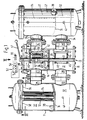
- FIGS. 1-5 The exemplary embodiment of a switchable double filter shown in FIGS. 1-5 has two filter housings 11 and 12, between which a switch fitting, designated as a whole by 13, is arranged.
- the housing 14 of the switching valve 13 is cylindrical and with it Axis arranged vertically.
- the interior of the housing 14 is divided approximately in the middle by a partition 15 into an upper dirt chamber 16 and a lower clean chamber 17.
- a switching shaft 21 is rotatably mounted in the upper and lower covers 18 and 19, as well as in the partition 15, the function of which will be explained in more detail below.
- the housing 14 of the switchover fitting 13 has an inlet connection 22 opening into the dirt chamber 16 for the liquid to be filtered, for example mineral oil or the like, and two connecting connections 23, 24 also opening into the dirt chamber of the housing 14 on, which can be connected to corresponding connections 25 and 26 by a flange connection and which open into dirt chambers 27 of the filter housings 11 and 12.
- the connecting pieces 28 and 29 are arranged under the connecting pieces 23 and 24, there is also an outlet piece for the filtered liquid which opens into the clean chamber 17 of the housing 14 and is not visible in the drawing.
- the interior of the filter housing 11 is divided by a partition 31 into the said dirt chamber 27 and a clean chamber 32 located below.
- a connecting piece 33 or 34 opens, which is connected by a flange connection to the connecting piece 28 or 29 of the housing 14 of the switchover fitting 13.
- each of the partitions 31 of the filter housings 11 and 12 there are at least two eccentrically arranged openings for the engagement of the outlet connections of commercially available filter elements 35, of which only one filter element 35 is shown in the left filter housing 11 in FIGS. 1, 2 and 6 .
- the filter element 35 has a cylindrical perforated sheet metal jacket and a filter which is folded in a star shape and comprises a suitable filter material, for example paper or inorganic fibers.
- a circular holding disc 36 is provided, which is held by a central column 37 which is fastened to the partition 31 by its lower end.
- each of the two dirt chambers 27 is provided directly above the partition 31 with a closable drain opening 39 for cleaning purposes.
- a closable opening 41 for the connection of a pressure measuring instrument.
- closure covers 42 and 43 located in the dirt chamber 16 and in the clean chamber 17.
- closure covers 42 and 43 has a circular cylindrical closure surface 44 adapted to the circular cylindrical inner wall of the housing 14 and is held by two holding rods 45, the free ends of which are connected to one another.
- the support rods 45 are mounted in diametrically through holes of the peeling shaft 21 so that they can be moved longitudinally.
- a helical compression spring 46 is arranged on each holding rod 45 between the selector shaft 21 and the sealing caps 42 and 43. These compression springs 46 press the closure covers 42 and 43 with their closure surfaces 44 against the cylindrical inner wall of the housing 14 and thereby close the mouth of the connecting piece 24 and 29.
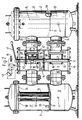
- an actuating lever 47 is arranged with 4, the selector shaft 21 can be rotated counterclockwise from the position shown in Figure 1 by 180 °, then the caps 42 and 43 are moved from the closed position shown in Figure 1 to a second closed position in which they the mouths close the connecting pieces 23 and 28 into the dirt or clean chamber of the housing 14. From this second closed position, the control shaft 21 can then be pivoted back into the closed position shown in FIG. 1 by turning the actuating lever 47 clockwise.
- a lifting cylinder 48 is provided, the cylinder body of which is closed at one end by a base 49 which is rotatably connected to the switching shaft 21 about the latter .
- the piston rod 51 of the lifting cylinder 48 is connected to the cover 42.
- the end of the cylinder body of the lifting cylinder 48 facing away from the bottom 49 is open to the dirt chamber 16, so that the pressure acting in the dirt chamber 16 also prevails in the space of the lifting cylinder 48 penetrated by the piston rod.
- the other space, not penetrated by the piston rod 51, of the lifting cylinder 48 is connected via a line to a 3/2-way valve 53 which, in the operating position shown in FIG.
- closure cover 42 counteracts the force exerted.
- this force can be chosen so large that the closure lid is lifted slightly from the inner wall, so that switching can then be carried out easily.
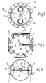
- the two connecting pieces 23 and 24 of the housing 14 are connected to one another via a pressure compensation valve 56, which is operated by means of an actuating lever 57 from the blocking position shown in FIG. 4, for pressure compensation in the dirt chambers 27 of the two filter housings 11 and 12 , can be switched to an open position.
- the two chambers of the filter housing 12 are also filled with the liquid. If the pressure in the dirt chamber 27 of the filter housing 11 is above a certain value due to contamination of the filter elements 35. For example, 6 bar increases, this is indicated by a measuring device. Then the switch armature switched to the second closed position, in which the liquid to be filtered is then fed to the dirt chamber of the filter housing 12. For this purpose, the pressure compensation valve 56 is first opened in order to produce a pressure compensation between the dirt chamber 16 of the housing 14 of the changeover valve 13 and the dirt chamber of the filter housing 12.
- the pressure rise in the dirt chamber 27 of the filter housing 12 caused by the opening of the pressure compensation valve 56 therefore only reaches a value which is only so much greater than the pressure in the clean chamber of the housing 14 that the pressure rise is sufficient to close the closure cover 43 of the clean chamber 17 to lift off the inner wall.
- This pressure increase leads to a pressure of, for example, 4.1 bar in the filter housing 12. This means that the closure cap 42 in the dirt chamber 16 of the housing 14 is still pressed not only by the spring 46 but also by the excess pressure of the liquid in the dirt chamber 16 against the inner wall of the housing 14.
- the space 52 of the lifting cylinder 48 is connected to the tub 55, so that the full pressure in the dirt chamber 16 acts on the piston of the lifting cylinder 48 and, if appropriate Dimensioning of the lifting cylinder slightly removes the closure cover 42 from the inner wall of the housing 14.
- the switching shaft 21 can be easily rotated by means of the actuating lever 47 by 180 ° into a position in which the closure covers 42 and 43 are in the diametrically opposite position in which they open the mouths of the connecting pieces 23 and 28 into the dirt chamber 16 or close the clean chamber 17.
- the liquid to be filtered still partly flows through the filter housing 11 and increasingly through the filter housing 12 until finally the flow only takes place through the filter housing 12. Filtration the liquid is not interrupted during this switching process.
- the switching process requires only a small force, since the cover 42 is lifted off the inner wall during the switching process.
- a lifting cylinder designed in the same way can also be provided for the closure cover 44 in the clean chamber 17.
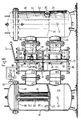
- the second exemplary embodiment shown in FIG. 6 differs from the first exemplary embodiment described above in that a lifting cylinder 61 is provided, the cylinder body of which is closed at both ends and the two cylinder spaces of which are connected to a 4/2-way valve 62, by means of which the a cylinder space of the lifting cylinder 61 with an external pressure medium source 63, e.g. with the pressure port of a pressure medium pump, and the other with a backflow connection 64 e.g. with a tub or the suction port of the pump, and vice versa.
- an external pressure medium source 63 e.g. with the pressure port of a pressure medium pump
- a backflow connection 64 e.g. with a tub or the suction port of the pump
- the same lifting cylinder 61 can be provided for the closure cover 43 in the clean chamber of the housing 14.
Landscapes
- Chemical & Material Sciences (AREA)
- Chemical Kinetics & Catalysis (AREA)
- Filtration Of Liquid (AREA)
- Multiple-Way Valves (AREA)
- Switches With Compound Operations (AREA)
Claims (10)
- Appareil de commutation ou d'inversion (13) pour liquides, notamment pour filtres jumelés réversibles pour lesdits fluides qui comprend :
une enveloppe (14) qui présente, au moins, une ouverture d'entrée et, au moins, deux ouvertures de sortie,
un corps de valve logé à l'intérieur de l'enveloppe (14) et qui peut être déplacé dans plusieurs positions dans lesquelles il fait communiquer, sélectivement, l'ouverture d'entrée avec l'une des ouvertures de sortie, caractérisé en ce que :
le corps de valve comporte un couvercle (42) pour fermer une ouverture de sortie et qui peut se déplacer le long de la paroi intérieure de l'enveloppe (14) obturer l'ouverture de sortie ne devant pas être mise en communication avec l'ouverture d'entrée,
qu'il comprend un élément de pression (46) qui presse le couvercle (42) contre l'ouverture devant être fermée, et
par un dispositif agissant sur le couvercle (42) de façon à diminuer ou à annuler la force avec laquelle le couvercle (42) est pressé contre la paroi intérieure de l'enveloppe (14) de l'appareil. - Appareil selon la revendication 1, caractérisé en ce que l'élément de pression est constitué par, au moins, un ressort (46).
- Appareil de commutation selon la revendication 1 ou 2, caractérisé en ce que le dispositif d'élévation comprend un cylindre (48, 61).
- Appareil de commutation selon la revendication 3, caractérisé en ce que l'actionnement du cylindre (61) est assuré par un cylindre de levage (61) est assuré par une source de fluide sous pression (63) et par une valve (62), au moyen desquels la source de fluide sous pression (63) peut être sélectivement mise en communication avec ou isolé du piston du cylindre de levage (61).
- Appareil de commutation selon la revendication 4, caractérisé en ce qu'il comprend une valve 4/2 voies (62) permettant de faire communiquer l'une des chambres du cylindre de levage (61) avec la source de fluide sous pression (63) et l'autre avec le raccord d'évacuation (64) et inversement.
- Appareil de commutation selon la revendication 3, caractérisé en ce que pour pouvoir commuter des fluides sous pression afin d'actionner le cylindre de levage (48) sa chambre, traversée par la tige de piston communique en permanence avec la chambre intérieure de l'enveloppe (14), tandis que son autre chambre (52) peut être reliée sélectivement par une valve (53) avec cette chambre intérieure ou avec un raccord d'évacuation (54).
- Appareil de commutation selon l'une des revendications 1 à 6, caractérisé en ce que :a) l'enveloppe (14) de l'appareil de commutation (13) a la forme d'un cylindre circulaire;b) l'élément de fermeture (42) forme une surface d'obturation cylindrique circulaire (44) adaptée à la paroi intérieure de même forme que l'enveloppe (14).c) qu'un arbre de commutation (21) coaxial à l'enveloppe (14) dont l'une des extrémités s'avance à l'extérieur de l'enveloppe (14) est prévu aux fins d'actionnement.d) en ce que l'obturateur coulissant (42) est relié radialement mobile avec l'arbre de commutation (21), et
en ce que l'extrémité orientée à l'opposé de l'élément de fermeture (42) est reliée à l'arbre de commutation (21). - Appareil de commutation selon l'une quelconque des revendications 1 à 7, pour un double filtre commutable, caractérisé en ce que l'enveloppe de l'appareil comporte une chambre à impuretés et une chambre propre (16 - 17);
en ce que la chambre à impuretés (16) est pourvue d'un conduit (22) pour l'entrée du liquide devant être filtré, tandis que la chambre propre (17) est pourvue d'un conduit (22) pour évacuer le liquide filtré, ces deux chambres étant également pourvues de conduits de liaison (23, 24 et 28, 29) qui relient respectivement les chambres à impuretés et propre (13 et 17) de l'enveloppe (14) avec les chambres impure et propre (27 et 32) de deux enveloppes de filtres (11, 12), et,
en ce que dans ses positions actives, l'élément de fermeture (42) clôt sélectivement le conduit (23 ou 24) reliant la chambre à impuretés de l'enveloppe (14) avec la chambre à impuretés (27) des deux enveloppes de filtres (11 et 12). - Appareil de commutation selon les revendications 7 et 8, caractérisé en ce que la chambre propre (17) comporte un couvercle (43) pour fermer sélectivement l'un des deux raccords (28 ou 29) qui relient la chambre propre (17) de l'enveloppe de l'appareil avec les chambres propres (32) des deux enveloppes (11, 12) des filtres; et
en ce que le couvercle de fermeture (43) est relié à l'arbre de commutation (21). - Appareil de commutation selon la revendication 9, caractérisé en ce que, pour diminuer la résistance de friction du couvercle (43) contre la paroi intérieure de la chambre propre de l'enveloppe, un dispositif de levage s'appliquant contre le couvercle (43) est prévu.
Priority Applications (1)
| Application Number | Priority Date | Filing Date | Title |
|---|---|---|---|
| AT90100078T ATE86875T1 (de) | 1989-06-13 | 1990-01-03 | Umschaltarmatur. |
Applications Claiming Priority (2)
| Application Number | Priority Date | Filing Date | Title |
|---|---|---|---|
| DE8907211U DE8907211U1 (fr) | 1989-06-13 | 1989-06-13 | |
| DE8907211U | 1989-06-13 |
Publications (3)
| Publication Number | Publication Date |
|---|---|
| EP0402559A2 EP0402559A2 (fr) | 1990-12-19 |
| EP0402559A3 EP0402559A3 (fr) | 1991-06-12 |
| EP0402559B1 true EP0402559B1 (fr) | 1993-03-17 |
Family
ID=6840042
Family Applications (1)
| Application Number | Title | Priority Date | Filing Date |
|---|---|---|---|
| EP90100078A Expired - Lifetime EP0402559B1 (fr) | 1989-06-13 | 1990-01-03 | Vanne de distribution |
Country Status (5)
| Country | Link |
|---|---|
| US (1) | US5073260A (fr) |
| EP (1) | EP0402559B1 (fr) |
| AT (1) | ATE86875T1 (fr) |
| DE (2) | DE8907211U1 (fr) |
| ES (1) | ES2039957T3 (fr) |
Families Citing this family (24)
| Publication number | Priority date | Publication date | Assignee | Title |
|---|---|---|---|---|
| USD244243S (en) * | 1975-12-17 | 1977-05-10 | Interstate Industries, Inc. | Shelf module, or similar article |
| JPH0773647B2 (ja) * | 1993-03-11 | 1995-08-09 | アスカ工業株式会社 | フィルター装置 |
| JPH0773648B2 (ja) * | 1993-03-11 | 1995-08-09 | アスカ工業株式会社 | フィルター装置 |
| ATE159551T1 (de) * | 1993-11-30 | 1997-11-15 | Danieli Off Mecc | Verfahren zum rückleiten von behandlungsgut bei oberflächenbehandlungen und fertigbearbeitungen |
| DE4406213A1 (de) * | 1994-02-25 | 1995-08-31 | Mediador Pumpentechnik Gmbh | Mehrwegehahn |
| US5443722A (en) * | 1994-06-01 | 1995-08-22 | Mueller Steam Specialty | Duplex strainer |
| US5770066A (en) * | 1996-11-04 | 1998-06-23 | Northeast Filter And Equipment Company | Convertible pressure vessel having a tie rod connecting a separator plate assembly and compression seal assembly |
| US5937903A (en) * | 1997-10-15 | 1999-08-17 | Pac-Fab, Inc. | High performance diverter valve |
| US6568428B2 (en) | 1998-07-23 | 2003-05-27 | Laars, Inc. | Backwash valve |
| DE19851193C1 (de) * | 1998-11-06 | 2000-04-13 | Hydac Filtertechnik Gmbh | Filteranordnung mit mindestens zwei Filterkammern |
| US6197195B1 (en) * | 1999-03-29 | 2001-03-06 | H-Tech, Inc. | Fluid handling apparatus and flow control assembly therefor |
| DE19946940A1 (de) * | 1999-09-30 | 2001-04-05 | Hydac Filtertechnik Gmbh | Filtervorrichtung mit mindestens zwei Filterkammern |
| SE525213C2 (sv) * | 2003-05-23 | 2004-12-28 | Hyosong M Lee | Förfarande och anordning för kontinuerlig filtrering av partiklar ur en vätska |
| US7849877B2 (en) | 2007-03-01 | 2010-12-14 | Zodiac Pool Systems, Inc. | Diverter valve |
| WO2010091388A1 (fr) * | 2009-02-09 | 2010-08-12 | Planar Solutions, Llc | Traitement de fluides |
| DE102009049712A1 (de) * | 2009-10-17 | 2011-04-21 | Hydac Process Technology Gmbh | Filtervorrichtung |
| DE102010022575A1 (de) * | 2010-06-02 | 2011-12-08 | Hydac Process Technology Gmbh | Schaltvorrichtung für einen Fluidstrom |
| DE102010025153A1 (de) * | 2010-06-25 | 2011-12-29 | Hydac Process Technology Gmbh | Schaltvorrichtung für einen Fluidstrom |
| WO2016025384A1 (fr) | 2014-08-14 | 2016-02-18 | Cummins, Inc. | Système de filtration de carburant |
| US10532296B1 (en) * | 2016-09-12 | 2020-01-14 | K.T.I. Systems, Inc. | Filter controller |
| US11679348B2 (en) * | 2017-12-29 | 2023-06-20 | Enercorp Engineered Solutions Inc. | Horizontal sand separator assembly |
| USD894328S1 (en) * | 2018-03-22 | 2020-08-25 | Mechanical Manufacturing Corporation | Modular filter system for enhanced user access |
| USD940269S1 (en) * | 2019-07-10 | 2022-01-04 | Amiad Water Systems Ltd. | Filtration system |
| USD938549S1 (en) * | 2019-07-10 | 2021-12-14 | Amiad Water Systems Ltd. | Filtration system |
Family Cites Families (4)
| Publication number | Priority date | Publication date | Assignee | Title |
|---|---|---|---|---|
| US3396845A (en) * | 1964-06-18 | 1968-08-13 | June S Bouskill | Water conditioning system |
| US3618781A (en) * | 1969-08-22 | 1971-11-09 | Parker Hannifin Corp | Duplex filtering device |
| DE3123292A1 (de) * | 1981-05-08 | 1982-12-02 | BBC Aktiengesellschaft Brown, Boveri & Cie., 5401 Baden, Aargau | Verfahren zum umschalten von doppelfilteranlagen und einrichtung zur durchfuehrung des verfahrens |
| DE3313539A1 (de) * | 1983-04-14 | 1984-10-18 | EPE Eppensteiner GmbH, 6834 Ketsch | Filtereinheit |
-
1989
- 1989-06-13 DE DE8907211U patent/DE8907211U1/de not_active Expired
-
1990
- 1990-01-03 AT AT90100078T patent/ATE86875T1/de not_active IP Right Cessation
- 1990-01-03 DE DE9090100078T patent/DE59001033D1/de not_active Expired - Fee Related
- 1990-01-03 EP EP90100078A patent/EP0402559B1/fr not_active Expired - Lifetime
- 1990-01-03 ES ES199090100078T patent/ES2039957T3/es not_active Expired - Lifetime
- 1990-04-11 US US07/507,495 patent/US5073260A/en not_active Expired - Fee Related
Also Published As
| Publication number | Publication date |
|---|---|
| EP0402559A3 (fr) | 1991-06-12 |
| DE8907211U1 (fr) | 1989-07-27 |
| ES2039957T3 (es) | 1993-10-01 |
| US5073260A (en) | 1991-12-17 |
| EP0402559A2 (fr) | 1990-12-19 |
| DE59001033D1 (de) | 1993-04-22 |
| ATE86875T1 (de) | 1993-04-15 |
Similar Documents
| Publication | Publication Date | Title |
|---|---|---|
| EP0402559B1 (fr) | Vanne de distribution | |
| EP0279177B1 (fr) | Vanne à volume de fuite | |
| DE2335214C3 (de) | Selbstreinigender Flüssigkeitsfilter | |
| DE3519203A1 (de) | Stellvorrichtung fuer eine tuer eines kraftfahrzeugs | |
| EP0230524A2 (fr) | Arrêt pour porte de véhicule automobile | |
| DE3500500C2 (fr) | ||
| WO2016162083A1 (fr) | Dispositif de filtration | |
| EP0195206B1 (fr) | Clapet piloté | |
| EP0120988B2 (fr) | Installation de filtration se rinçant à contre-courant | |
| EP0112977A1 (fr) | Organe d'arrêt pour fluides agressifs | |
| DE3835363C2 (de) | Verfahren und Vorrichtung zur Steuerung des Mediumeintritts in wenigstens einen Leckageraum einer Ventilvorrichtung | |
| DE2818787C2 (de) | Doppelsitzventil mit Leckkontrolle | |
| DE3918667A1 (de) | Rueckspuelbare filterarmatur | |
| DE3330135C2 (de) | Selbstschlußarmatur | |
| EP0046162B1 (fr) | Robinet mélangeur comportant un bras de levier pour conduire un courant d'eau | |
| DE3822217A1 (de) | Sanitaeres einhebel-mischventil | |
| EP0240728B1 (fr) | Tuyau à dispositif de séparation | |
| EP0195389B2 (fr) | Déconnecteur de tuyaux | |
| WO2014146751A1 (fr) | Unité d'entretien pneumatique | |
| DE2757447B2 (de) | Rückspülbare Filtereinrichtung | |
| DE4323893C1 (de) | Filterkopf | |
| DE102007007870A1 (de) | Mehrwegeventil | |
| DE3024545C2 (de) | Vorrichtung zum Absperren und Belüften einer Rohrleitung | |
| DE3024559C2 (de) | Stellvorrichtung für ein Absperrventil | |
| DE3433569A1 (de) | Steuerschieber zum einbau in die abgasleitung von kraftfahrzeugen o.dgl. |
Legal Events
| Date | Code | Title | Description |
|---|---|---|---|
| PUAI | Public reference made under article 153(3) epc to a published international application that has entered the european phase |
Free format text: ORIGINAL CODE: 0009012 |
|
| AK | Designated contracting states |
Kind code of ref document: A2 Designated state(s): AT CH DE ES FR GB IT LI NL SE |
|
| PUAL | Search report despatched |
Free format text: ORIGINAL CODE: 0009013 |
|
| AK | Designated contracting states |
Kind code of ref document: A3 Designated state(s): AT CH DE ES FR GB IT LI NL SE |
|
| 17P | Request for examination filed |
Effective date: 19911107 |
|
| 17Q | First examination report despatched |
Effective date: 19920519 |
|
| GRAA | (expected) grant |
Free format text: ORIGINAL CODE: 0009210 |
|
| ITF | It: translation for a ep patent filed |
Owner name: INTERPATENT ST.TECN. BREV. |
|
| AK | Designated contracting states |
Kind code of ref document: B1 Designated state(s): AT CH DE ES FR GB IT LI NL SE |
|
| REF | Corresponds to: |
Ref document number: 86875 Country of ref document: AT Date of ref document: 19930415 Kind code of ref document: T |
|
| ET | Fr: translation filed | ||
| REF | Corresponds to: |
Ref document number: 59001033 Country of ref document: DE Date of ref document: 19930422 |
|
| GBT | Gb: translation of ep patent filed (gb section 77(6)(a)/1977) |
Effective date: 19930331 |
|
| REG | Reference to a national code |
Ref country code: ES Ref legal event code: FG2A Ref document number: 2039957 Country of ref document: ES Kind code of ref document: T3 |
|
| PLBE | No opposition filed within time limit |
Free format text: ORIGINAL CODE: 0009261 |
|
| STAA | Information on the status of an ep patent application or granted ep patent |
Free format text: STATUS: NO OPPOSITION FILED WITHIN TIME LIMIT |
|
| 26N | No opposition filed | ||
| EAL | Se: european patent in force in sweden |
Ref document number: 90100078.6 |
|
| PGFP | Annual fee paid to national office [announced via postgrant information from national office to epo] |
Ref country code: GB Payment date: 20011211 Year of fee payment: 13 |
|
| PGFP | Annual fee paid to national office [announced via postgrant information from national office to epo] |
Ref country code: FR Payment date: 20011228 Year of fee payment: 13 |
|
| REG | Reference to a national code |
Ref country code: GB Ref legal event code: IF02 |
|
| PGFP | Annual fee paid to national office [announced via postgrant information from national office to epo] |
Ref country code: SE Payment date: 20020104 Year of fee payment: 13 |
|
| PGFP | Annual fee paid to national office [announced via postgrant information from national office to epo] |
Ref country code: ES Payment date: 20020118 Year of fee payment: 13 |
|
| PGFP | Annual fee paid to national office [announced via postgrant information from national office to epo] |
Ref country code: DE Payment date: 20020121 Year of fee payment: 13 |
|
| PGFP | Annual fee paid to national office [announced via postgrant information from national office to epo] |
Ref country code: CH Payment date: 20020123 Year of fee payment: 13 |
|
| PGFP | Annual fee paid to national office [announced via postgrant information from national office to epo] |
Ref country code: AT Payment date: 20020130 Year of fee payment: 13 |
|
| PGFP | Annual fee paid to national office [announced via postgrant information from national office to epo] |
Ref country code: NL Payment date: 20020131 Year of fee payment: 13 |
|
| PG25 | Lapsed in a contracting state [announced via postgrant information from national office to epo] |
Ref country code: GB Free format text: LAPSE BECAUSE OF NON-PAYMENT OF DUE FEES Effective date: 20030103 Ref country code: AT Free format text: LAPSE BECAUSE OF NON-PAYMENT OF DUE FEES Effective date: 20030103 |
|
| PG25 | Lapsed in a contracting state [announced via postgrant information from national office to epo] |
Ref country code: SE Free format text: LAPSE BECAUSE OF NON-PAYMENT OF DUE FEES Effective date: 20030104 Ref country code: ES Free format text: LAPSE BECAUSE OF NON-PAYMENT OF DUE FEES Effective date: 20030104 |
|
| PG25 | Lapsed in a contracting state [announced via postgrant information from national office to epo] |
Ref country code: LI Free format text: LAPSE BECAUSE OF NON-PAYMENT OF DUE FEES Effective date: 20030131 Ref country code: CH Free format text: LAPSE BECAUSE OF NON-PAYMENT OF DUE FEES Effective date: 20030131 |
|
| PG25 | Lapsed in a contracting state [announced via postgrant information from national office to epo] |
Ref country code: NL Free format text: LAPSE BECAUSE OF NON-PAYMENT OF DUE FEES Effective date: 20030801 Ref country code: DE Free format text: LAPSE BECAUSE OF NON-PAYMENT OF DUE FEES Effective date: 20030801 |
|
| GBPC | Gb: european patent ceased through non-payment of renewal fee |
Effective date: 20030103 |
|
| EUG | Se: european patent has lapsed | ||
| REG | Reference to a national code |
Ref country code: CH Ref legal event code: PL |
|
| PG25 | Lapsed in a contracting state [announced via postgrant information from national office to epo] |
Ref country code: FR Free format text: LAPSE BECAUSE OF NON-PAYMENT OF DUE FEES Effective date: 20030930 |
|
| NLV4 | Nl: lapsed or anulled due to non-payment of the annual fee |
Effective date: 20030801 |
|
| REG | Reference to a national code |
Ref country code: FR Ref legal event code: ST |
|
| REG | Reference to a national code |
Ref country code: ES Ref legal event code: FD2A Effective date: 20030104 |
|
| PG25 | Lapsed in a contracting state [announced via postgrant information from national office to epo] |
Ref country code: IT Free format text: LAPSE BECAUSE OF NON-PAYMENT OF DUE FEES;WARNING: LAPSES OF ITALIAN PATENTS WITH EFFECTIVE DATE BEFORE 2007 MAY HAVE OCCURRED AT ANY TIME BEFORE 2007. THE CORRECT EFFECTIVE DATE MAY BE DIFFERENT FROM THE ONE RECORDED. Effective date: 20050103 |