EP1013942A2 - Elément de commande pour un fluide - Google Patents
Elément de commande pour un fluide Download PDFInfo
- Publication number
- EP1013942A2 EP1013942A2 EP99125319A EP99125319A EP1013942A2 EP 1013942 A2 EP1013942 A2 EP 1013942A2 EP 99125319 A EP99125319 A EP 99125319A EP 99125319 A EP99125319 A EP 99125319A EP 1013942 A2 EP1013942 A2 EP 1013942A2
- Authority
- EP
- European Patent Office
- Prior art keywords
- sealing
- control
- control chamber
- seats
- chamber
- Prior art date
- Legal status (The legal status is an assumption and is not a legal conclusion. Google has not performed a legal analysis and makes no representation as to the accuracy of the status listed.)
- Granted
Links
Images


Classifications
-
- F—MECHANICAL ENGINEERING; LIGHTING; HEATING; WEAPONS; BLASTING
- F15—FLUID-PRESSURE ACTUATORS; HYDRAULICS OR PNEUMATICS IN GENERAL
- F15B—SYSTEMS ACTING BY MEANS OF FLUIDS IN GENERAL; FLUID-PRESSURE ACTUATORS, e.g. SERVOMOTORS; DETAILS OF FLUID-PRESSURE SYSTEMS, NOT OTHERWISE PROVIDED FOR
- F15B11/00—Servomotor systems without provision for follow-up action; Circuits therefor
- F15B11/006—Hydraulic "Wheatstone bridge" circuits, i.e. with four nodes, P-A-T-B, and on-off or proportional valves in each link
-
- F—MECHANICAL ENGINEERING; LIGHTING; HEATING; WEAPONS; BLASTING
- F15—FLUID-PRESSURE ACTUATORS; HYDRAULICS OR PNEUMATICS IN GENERAL
- F15B—SYSTEMS ACTING BY MEANS OF FLUIDS IN GENERAL; FLUID-PRESSURE ACTUATORS, e.g. SERVOMOTORS; DETAILS OF FLUID-PRESSURE SYSTEMS, NOT OTHERWISE PROVIDED FOR
- F15B13/00—Details of servomotor systems ; Valves for servomotor systems
- F15B13/02—Fluid distribution or supply devices characterised by their adaptation to the control of servomotors
- F15B13/04—Fluid distribution or supply devices characterised by their adaptation to the control of servomotors for use with a single servomotor
- F15B13/0401—Valve members; Fluid interconnections therefor
- F15B13/0405—Valve members; Fluid interconnections therefor for seat valves, i.e. poppet valves
-
- F—MECHANICAL ENGINEERING; LIGHTING; HEATING; WEAPONS; BLASTING
- F15—FLUID-PRESSURE ACTUATORS; HYDRAULICS OR PNEUMATICS IN GENERAL
- F15B—SYSTEMS ACTING BY MEANS OF FLUIDS IN GENERAL; FLUID-PRESSURE ACTUATORS, e.g. SERVOMOTORS; DETAILS OF FLUID-PRESSURE SYSTEMS, NOT OTHERWISE PROVIDED FOR
- F15B13/00—Details of servomotor systems ; Valves for servomotor systems
- F15B13/02—Fluid distribution or supply devices characterised by their adaptation to the control of servomotors
- F15B13/04—Fluid distribution or supply devices characterised by their adaptation to the control of servomotors for use with a single servomotor
- F15B13/044—Fluid distribution or supply devices characterised by their adaptation to the control of servomotors for use with a single servomotor operated by electrically-controlled means, e.g. solenoids, torque-motors
-
- F—MECHANICAL ENGINEERING; LIGHTING; HEATING; WEAPONS; BLASTING
- F16—ENGINEERING ELEMENTS AND UNITS; GENERAL MEASURES FOR PRODUCING AND MAINTAINING EFFECTIVE FUNCTIONING OF MACHINES OR INSTALLATIONS; THERMAL INSULATION IN GENERAL
- F16K—VALVES; TAPS; COCKS; ACTUATING-FLOATS; DEVICES FOR VENTING OR AERATING
- F16K31/00—Actuating devices; Operating means; Releasing devices
- F16K31/02—Actuating devices; Operating means; Releasing devices electric; magnetic
- F16K31/06—Actuating devices; Operating means; Releasing devices electric; magnetic using a magnet, e.g. diaphragm valves, cutting off by means of a liquid
- F16K31/0682—Actuating devices; Operating means; Releasing devices electric; magnetic using a magnet, e.g. diaphragm valves, cutting off by means of a liquid with an articulated or pivot armature
-
- F—MECHANICAL ENGINEERING; LIGHTING; HEATING; WEAPONS; BLASTING
- F15—FLUID-PRESSURE ACTUATORS; HYDRAULICS OR PNEUMATICS IN GENERAL
- F15B—SYSTEMS ACTING BY MEANS OF FLUIDS IN GENERAL; FLUID-PRESSURE ACTUATORS, e.g. SERVOMOTORS; DETAILS OF FLUID-PRESSURE SYSTEMS, NOT OTHERWISE PROVIDED FOR
- F15B2211/00—Circuits for servomotor systems
- F15B2211/30—Directional control
- F15B2211/305—Directional control characterised by the type of valves
- F15B2211/3056—Assemblies of multiple valves
- F15B2211/30565—Assemblies of multiple valves having multiple valves for a single output member, e.g. for creating higher valve function by use of multiple valves like two 2/2-valves replacing a 5/3-valve
- F15B2211/30575—Assemblies of multiple valves having multiple valves for a single output member, e.g. for creating higher valve function by use of multiple valves like two 2/2-valves replacing a 5/3-valve in a Wheatstone Bridge arrangement (also half bridges)
-
- F—MECHANICAL ENGINEERING; LIGHTING; HEATING; WEAPONS; BLASTING
- F15—FLUID-PRESSURE ACTUATORS; HYDRAULICS OR PNEUMATICS IN GENERAL
- F15B—SYSTEMS ACTING BY MEANS OF FLUIDS IN GENERAL; FLUID-PRESSURE ACTUATORS, e.g. SERVOMOTORS; DETAILS OF FLUID-PRESSURE SYSTEMS, NOT OTHERWISE PROVIDED FOR
- F15B2211/00—Circuits for servomotor systems
- F15B2211/30—Directional control
- F15B2211/32—Directional control characterised by the type of actuation
- F15B2211/327—Directional control characterised by the type of actuation electrically or electronically
-
- Y—GENERAL TAGGING OF NEW TECHNOLOGICAL DEVELOPMENTS; GENERAL TAGGING OF CROSS-SECTIONAL TECHNOLOGIES SPANNING OVER SEVERAL SECTIONS OF THE IPC; TECHNICAL SUBJECTS COVERED BY FORMER USPC CROSS-REFERENCE ART COLLECTIONS [XRACs] AND DIGESTS
- Y10—TECHNICAL SUBJECTS COVERED BY FORMER USPC
- Y10T—TECHNICAL SUBJECTS COVERED BY FORMER US CLASSIFICATION
- Y10T137/00—Fluid handling
- Y10T137/8593—Systems
- Y10T137/86493—Multi-way valve unit
- Y10T137/86847—Pivoted valve unit
-
- Y—GENERAL TAGGING OF NEW TECHNOLOGICAL DEVELOPMENTS; GENERAL TAGGING OF CROSS-SECTIONAL TECHNOLOGIES SPANNING OVER SEVERAL SECTIONS OF THE IPC; TECHNICAL SUBJECTS COVERED BY FORMER USPC CROSS-REFERENCE ART COLLECTIONS [XRACs] AND DIGESTS
- Y10—TECHNICAL SUBJECTS COVERED BY FORMER USPC
- Y10T—TECHNICAL SUBJECTS COVERED BY FORMER US CLASSIFICATION
- Y10T137/00—Fluid handling
- Y10T137/8593—Systems
- Y10T137/87169—Supply and exhaust
- Y10T137/87217—Motor
-
- Y—GENERAL TAGGING OF NEW TECHNOLOGICAL DEVELOPMENTS; GENERAL TAGGING OF CROSS-SECTIONAL TECHNOLOGIES SPANNING OVER SEVERAL SECTIONS OF THE IPC; TECHNICAL SUBJECTS COVERED BY FORMER USPC CROSS-REFERENCE ART COLLECTIONS [XRACs] AND DIGESTS
- Y10—TECHNICAL SUBJECTS COVERED BY FORMER USPC
- Y10T—TECHNICAL SUBJECTS COVERED BY FORMER US CLASSIFICATION
- Y10T137/00—Fluid handling
- Y10T137/8593—Systems
- Y10T137/877—With flow control means for branched passages
- Y10T137/87708—With common valve operator
- Y10T137/87772—With electrical actuation
Definitions
- the invention relates to a control element for fluid, with a Housing in which two control chambers are formed, which are against each other are isolated and each have a work connection and two Have pressure connections, two of the connections with each a sealing seat are provided, a switching element that is movable in Housing is mounted and a sealing part in each control chamber has that can cooperate with the sealing seats such that these are open or closed, and with an actuator for the switching element.
- Such a control element is from US Pat. No. 4,765,370 known. It represents a 4/2-way valve with which, for example hydraulic actuating cylinders can be controlled. If, for example a double-acting hydraulic cylinder is controlled the working connection of a control chamber with one Working chamber of the hydraulic cylinder and the working connection of the another control chamber with the other working chamber of the hydraulic cylinder connected. In a first position of the switching element, the Rest position, the one working chamber of the hydraulic cylinder Pressurized so that movement in a first direction takes place while in an activated position of the switching element, in which the switching element is moved by an electromagnet, which other working chamber of the hydraulic piston pressurized is, so that a movement takes place in the opposite direction.
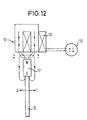
- a hydraulic piston 1 is shown schematically in FIG is arranged between two working chambers 2, 3.
- the Working Chamber 2 is with a working connection A of a schematically shown and with 4/3-way control element provided with reference number 10, and the working chamber 3 is connected to a working port B.
- two pressure ports P, R are provided, port P provides a pressurized fluid and port R one Reflux line forms.
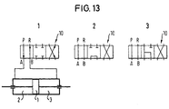
- the control shown as example 1 enables three Operating states.
- the hydraulic piston is in the left switch position 1 to the right. In the middle switch position the hydraulic piston 1 is blocked. In the left switch position hydraulic piston 1 is actuated to the left.
- Examples 2 and 3 also allow three switch positions, the left and right switch positions with the right and the left switch position of the first example match.
- the middle switching position in Example 2 causes the Hydraulic piston 1 is freely movable, and the middle switching position of Example 3 causes the hydraulic piston 1 with that of Pressure port P provided pressure is blocked.
- the object of the invention is a simple, direct create effective control element with 4/3 mode of action and thereby the technical expenditure for a cylinder control reduce as well as a more direct, faster control of To enable actuators or actuators.
- the Actuator can bring the switching element in three positions.
- the desired three switch positions can be achieved without additional slide valves are required.
- Such an actuator, with which the switching element is brought into the three positions can be, for example, an electromagnetic drive with polarized drive element, the permanent magnet in the de-energized State of its coil holds the switching element in a central position, which also represents the rest position, and when current flows through Depending on the current direction, the switching element in one or changed the other direction.
- the sealing seats of a control chamber each other opposite on one and the other side of the control chamber are arranged and the sealing part arranged in this control chamber is formed with two opposite tongues, the are arranged between the sealing seats, resiliently are designed and in the rest position such a distance from each other that they have the two sealing seats at the same time can close.
- all connections are locked in the middle or rest position.
- the sealing seats one Control chamber facing each other on one and the other Side of the control chamber are arranged and in this control chamber arranged sealing part either on one or the other Fits tight.
- this embodiment is in the rest position one sealing seat per control chamber closed.
- the Sealing seats of a control chamber offset against each other on one and the other side of the control chamber are arranged in this control chamber arranged sealing part with two side by side Tongues are formed, each of which is one of the sealing seats assigned and resilient.
- This design works basically like the one described above with the two opposite tongues, but a larger number of switching states is possible.
- one of the Control chambers the design described above with each other opposite sealing seats and opposite tongues be provided while in the other control chamber the design with staggered sealing seats and side by side Tongues is used.
- the tongues of the sealing parts arranged in the two control chambers of the switching element extend in the same plane.
- the same Effect can be achieved when the two are in a tax chamber arranged tongues are offset from each other.
- the sealing seats are in the two Control chambers arranged so that the tongues of the sealing parts in the Rest position on all sealing seats in the two control chambers issue.
- the sealing seats in the two Control chambers are arranged so that the tongues of the sealing parts in the rest position on all sealing seats of a single control chamber and do not rest on any sealing seat of the other control chamber.
- the sealing seats in the two control chambers are arranged that the tongues of the sealing parts in the rest position rest against a sealing seat in each control chamber.
- any desired Actuation type of an actuator for example a hydraulic one Actuating cylinder can be achieved.
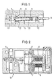
- the control element 10 has a housing 12 in which two adjacent, isolated control chambers 20, 30, of which in Figure 1 shows only one. Open in each tax chamber Work port and two pressure ports, the work port is designated with A or B and the pressure connections with P or R are designated. Two of the ports in each control chamber 20 and 30, respectively are provided with a sealing seat 21, 22 or 31, 32. With the sealing seats 21, 22 and 31, 32 operate generally with the reference number 14 provided switching element together.
- the switching element 14 can by Acting on an actuation extension 15 from a rest position can be moved out into a first and a second position. A total of three positions of the switching element 14 are possible.
- An actuating member 16 is used to actuate the switching element 14 provided (see also Figure 12), for example as electromagnetic drive with a polarized drive element is executed, the permanent magnet in the de-energized state of a coil causes a middle position of the actuation extension 15 and at Current flow as a function of the current direction the actuating arm either in the direction of arrow 1 or in the direction of arrow 2 adjusted.
- the basic structure of the switching element 14, which consists of a Core 11 and a surrounding elastomer 13, and the Storage of the switching element in the housing 12 is basically from the German utility model 295 07 380 known to the express Reference is made. The details of the design of the switching element are therefore not further explained here.
- each sealing part 24, 34 are fixed to the Actuating extension 15 connected and are simultaneously with the Actuation process moves.
- Am free in the appropriate tax chamber protruding end is each sealing part 24, 34 with two tongues 26, 28 or 36, 38 provided.
- the two tongues 26, 28 and 36, 38 are opposite each other and formed elastically resilient.
- one of the tongues by an offset of the corresponding sealing part are formed, while the opposite Tongue through an additional mirrored part Part is formed, for example, with the sealing part Spot welding is connected.
- the sealing seats 21, 22 arranged in the control chambers 20, 30 and 31, 32 are configured opposite one another (see FIG 3). Although not necessarily the case, they do Sealing seats 21, 22 and 31, 32 associated connections the same Central axis; the corresponding sealing seats are therefore concentric arranged to each other. The side of the sealing seats opens into everyone Control chamber the remaining port.
- the connections are assigned so that the sealing seats are assigned to two pressure connections P, R during the Work connection A or B opens laterally.
- the switching element 14 has two sealing parts 24, 34 arranged side by side, which in are arranged on the same level (see in particular FIG. 6).
- the control chambers 20, 30 arranged sealing seats 21, 22 and 31, 32 protrude differently into the control chambers. As in Figure 6 too is seen, it protrudes on the upper side of the control chamber 20 arranged sealing seat 21 so far into the control chamber that it bears against the sealing part 24 located in the starting position. In similarly protrudes on the lower side of the control chamber 30 arranged sealing seat 32 so far into the control chamber 30 that he rests on the sealing part 34 which is in the rest position.
- the sealing seat arranged on the lower side of the control chamber 20 22 and that arranged on the upper side of the control chamber 30 Sealing seat 31 are at a distance from which is in the rest position located sealing part 24 and 34 respectively.
- the switching element can be moved in two positions.
- a first position in which the two sealing parts 24, 34 upwards are applied the sealing member 24 does not move further because it already lies against the sealing seat 21 and is elastically deformed.
- the sealing part 34 is lifted from the sealing seat 32 and against pressed the sealing seat 31. So in this position Pressure port P with the working port B of the control chamber 30 connected while no change regarding the control chamber 20 of the switching state occurs. If, however, from the rest position out the sealing parts 24, 34 are applied downwards results no change in the control chamber 30 Switching state, while the sealing member 24 is lifted from the sealing seat 21 and is pressed against the sealing seat 22. So in this case the pressure connection here designated P 'with the working connection A the control chamber 20 connected.
- FIG. 7 shows a variant of that in FIGS. 5 and 6 shown second embodiment.
- the difference is that here on the top of the control chambers 20, 30 arranged sealing seats, 21, 31 and those on the lower Side of the control chambers arranged sealing seats 22, 32 each are at the same level.
- the sealing parts 24, 34 no longer arranged in the same plane, but against each other crossed.
- the mode of action is similar to that of the second Embodiment. If starting from that shown in Figure 7 The sealing parts 24, 34 are acted upon in the rest position, there is no change in the control chamber 20 Switching state, while the sealing member 34 in the control chamber 30 from Sealing seat 32 is lifted off and pressed against sealing seat 31. If on the other hand, the sealing parts 24, 34 are acted on downwards no change in the control chamber 30 Switching state, while the sealing part 24 of the control chamber 20 from Sealing seat 21 is lifted and pressed against the sealing seat 22.
- a third embodiment will now be described with reference to FIGS. 8 and 9 described a control element according to the invention.
- 30 Sealing seats are no longer formed coaxially opposite one another, but offset against each other, as can be seen in Figure 8.
- the sealing part of the protruding into the control chamber 20 or 30 Switching element 14 consists of two for each control chamber tongues arranged side by side. Thus protrude into the control chamber 20 two tongues 26, 28 into it, and two protrude into the control chamber 30 Tongues 36, 38 into it. All tongues 26, 28, 36, 38 extend in the rest position on the same level. As can be seen in Figure 8 the distance of the level defined by the sealing seats 21, 31 from the level defined by the sealing seats 22, 32 so that all tongues in the rest position of the switching element 14 to the seal seats assigned to them and close them. In the rest position shown in Figure 8 are thus all connections blocked.
- Tongues 26, 28, 36, 38 are applied upwards, results with regard to the tongues 26, 36 no change in the state, since these Just give tongues elastic and continue to the appropriate sealing seats. However, the tongues 28, 38 lifted off the sealing seats 22, 32 assigned to them, and the Working port A of the control chamber 20 is connected to the pressure port R connected, while the working port B of the control chamber 30 with the Pressure port P is connected.
- the representations a to e are different Controls shown according to the third embodiment, in which each time by changing the distance of the sealing seats from the associated tongues in the rest position and by different Assignment of the different connections different switching states be achieved.
- the resulting switching states can be omitted the representations and the circuit symbols also given remove, so that they are not described in detail here.
- the representations a to e are different Controls shown, which is a variant of the third embodiment represent and are based on the basic idea known from FIG. 7, that the tongues of the switching element are intertwined. This way you can interact with different ones Assignments of the connections and different distances between the sealing seats and the tongues in the rest position the same Achieve switching states as shown in representations a to e of Figure 10 are shown.
Landscapes
- Engineering & Computer Science (AREA)
- General Engineering & Computer Science (AREA)
- Mechanical Engineering (AREA)
- Physics & Mathematics (AREA)
- Fluid Mechanics (AREA)
- Multiple-Way Valves (AREA)
- Electrically Driven Valve-Operating Means (AREA)
Applications Claiming Priority (2)
| Application Number | Priority Date | Filing Date | Title |
|---|---|---|---|
| DE29822959U | 1998-12-23 | ||
| DE29822959U DE29822959U1 (de) | 1998-12-23 | 1998-12-23 | Steuerelement für Fluid |
Publications (3)
| Publication Number | Publication Date |
|---|---|
| EP1013942A2 true EP1013942A2 (fr) | 2000-06-28 |
| EP1013942A3 EP1013942A3 (fr) | 2000-07-26 |
| EP1013942B1 EP1013942B1 (fr) | 2004-09-22 |
Family
ID=8067116
Family Applications (1)
| Application Number | Title | Priority Date | Filing Date |
|---|---|---|---|
| EP99125319A Expired - Lifetime EP1013942B1 (fr) | 1998-12-23 | 1999-12-20 | Elément de commande pour un fluide |
Country Status (3)
| Country | Link |
|---|---|
| US (2) | US6286548B1 (fr) |
| EP (1) | EP1013942B1 (fr) |
| DE (2) | DE29822959U1 (fr) |
Cited By (1)
| Publication number | Priority date | Publication date | Assignee | Title |
|---|---|---|---|---|
| DE102008039420A1 (de) * | 2008-08-13 | 2010-02-18 | Prettl, Rolf | Fluidwegeventil |
Families Citing this family (11)
| Publication number | Priority date | Publication date | Assignee | Title |
|---|---|---|---|---|
| US7156121B2 (en) * | 2003-12-11 | 2007-01-02 | Cox Christopher L | Valve position monitor and method of use |
| DE102004021765A1 (de) * | 2004-04-30 | 2005-11-24 | Günter Biechele | Klappenventil |
| WO2006012510A1 (fr) | 2004-07-23 | 2006-02-02 | Afa Controls, Llc | Ensembles micro-soupapes et procedes associes |
| DE202006004749U1 (de) * | 2006-03-24 | 2006-06-29 | Bürkert Werke GmbH & Co. KG | Vorrichtung und Ventilkombination zur Fließumkehr von strömenden Medien |
| DE102007004377A1 (de) * | 2007-01-29 | 2008-08-07 | Diener Precision Pumps Ltd. | Elektromagnetisch zu betätigendes Ventil |
| EP2365239B1 (fr) | 2010-03-12 | 2015-03-04 | Asco Numatics GmbH | Dispositif destiné à la régulation du débit d'un milieu liquide ou gazeux |
| DE102010051743B4 (de) | 2010-11-19 | 2022-09-01 | C. Miethke Gmbh & Co. Kg | Programmierbares Hydrocephalusventil |
| US20120175385A1 (en) * | 2011-01-07 | 2012-07-12 | Fluid Management Operations, Llc | Valve Assembly for a Dispenser for Fluids |
| US9494240B2 (en) * | 2011-01-07 | 2016-11-15 | Fast & Fluid Management B.V. | Valve assembly for a dispenser for fluids |
| GB201115726D0 (en) * | 2011-09-12 | 2011-10-26 | Cambridge Entpr Ltd | Electromagnetic flexure |
| DE102016114538B4 (de) * | 2016-08-05 | 2023-08-03 | Bürkert Werke GmbH | Dichtungsvorrichtung für ein Ventil sowie Ventil |
Citations (6)
| Publication number | Priority date | Publication date | Assignee | Title |
|---|---|---|---|---|
| FR1249404A (fr) * | 1959-11-14 | 1960-12-30 | Rech Etudes Production Sarl | Vérin hydraulique autonome à alimentation électrique et à commande électrique |
| US4535810A (en) * | 1984-03-27 | 1985-08-20 | Dynamic Valves, Inc. | Electrically controlled valves |
| DE3630200A1 (de) * | 1986-09-04 | 1988-03-17 | Rexroth Mannesmann Gmbh | Hydraulisches servoventil |
| US4765370A (en) * | 1985-11-29 | 1988-08-23 | Fujikura Rubber Ltd. | Directional control valve |
| US4938249A (en) * | 1986-10-30 | 1990-07-03 | United Technologies Corporation | Chip tolerant flapper |
| DE29507380U1 (de) * | 1995-05-03 | 1995-08-24 | Bürkert Werke GmbH & Co., 74653 Ingelfingen | Fluidisches Steuerelement |
Family Cites Families (4)
| Publication number | Priority date | Publication date | Assignee | Title |
|---|---|---|---|---|
| US4131130A (en) * | 1977-07-18 | 1978-12-26 | Sperry Rand Corporation | Pneumatic pressure control valve |
| WO1982003431A1 (fr) * | 1981-03-25 | 1982-10-14 | Parker Graham Alexander | Dispositif de commande electro-fluide |
| DE3437487A1 (de) * | 1984-10-12 | 1986-04-17 | H. Kuhnke Gmbh Kg, 2427 Malente | Bistabiles magnetventil |
| DE29718306U1 (de) * | 1997-10-15 | 1998-01-22 | Bürkert Werke GmbH & Co., 74653 Ingelfingen | Piezoventil |
-
1998
- 1998-12-23 DE DE29822959U patent/DE29822959U1/de not_active Expired - Lifetime
-
1999
- 1999-12-15 US US09/461,384 patent/US6286548B1/en not_active Expired - Fee Related
- 1999-12-20 DE DE59910579T patent/DE59910579D1/de not_active Expired - Lifetime
- 1999-12-20 EP EP99125319A patent/EP1013942B1/fr not_active Expired - Lifetime
-
2001
- 2001-07-23 US US09/909,750 patent/US6371160B2/en not_active Expired - Fee Related
Patent Citations (6)
| Publication number | Priority date | Publication date | Assignee | Title |
|---|---|---|---|---|
| FR1249404A (fr) * | 1959-11-14 | 1960-12-30 | Rech Etudes Production Sarl | Vérin hydraulique autonome à alimentation électrique et à commande électrique |
| US4535810A (en) * | 1984-03-27 | 1985-08-20 | Dynamic Valves, Inc. | Electrically controlled valves |
| US4765370A (en) * | 1985-11-29 | 1988-08-23 | Fujikura Rubber Ltd. | Directional control valve |
| DE3630200A1 (de) * | 1986-09-04 | 1988-03-17 | Rexroth Mannesmann Gmbh | Hydraulisches servoventil |
| US4938249A (en) * | 1986-10-30 | 1990-07-03 | United Technologies Corporation | Chip tolerant flapper |
| DE29507380U1 (de) * | 1995-05-03 | 1995-08-24 | Bürkert Werke GmbH & Co., 74653 Ingelfingen | Fluidisches Steuerelement |
Cited By (3)
| Publication number | Priority date | Publication date | Assignee | Title |
|---|---|---|---|---|
| DE102008039420A1 (de) * | 2008-08-13 | 2010-02-18 | Prettl, Rolf | Fluidwegeventil |
| DE102008039420B4 (de) * | 2008-08-13 | 2011-04-28 | Prettl, Rolf | Fluidwegeventil |
| US8403002B2 (en) | 2008-08-13 | 2013-03-26 | Rolf Prettl | Directional control fluid valve |
Also Published As
| Publication number | Publication date |
|---|---|
| US6371160B2 (en) | 2002-04-16 |
| EP1013942A3 (fr) | 2000-07-26 |
| US20010039968A1 (en) | 2001-11-15 |
| US6286548B1 (en) | 2001-09-11 |
| DE59910579D1 (de) | 2004-10-28 |
| DE29822959U1 (de) | 1999-05-12 |
| EP1013942B1 (fr) | 2004-09-22 |
Similar Documents
| Publication | Publication Date | Title |
|---|---|---|
| EP0764784B1 (fr) | Dispositif de commande pour une soupape à voies multiples | |
| EP0719395B1 (fr) | Soupape modulaire pour milieux en ecoulement | |
| DE69704045T2 (de) | Steuerventilverteilerplatte mit innerer oder äusserer Steuerschaltung | |
| DE2737675A1 (de) | Umschaltventil mit magnetventilsteuerung | |
| DE3323363A1 (de) | Vorgesteuertes druckreduzierventil | |
| EP1013942B1 (fr) | Elément de commande pour un fluide | |
| DE1750358B2 (de) | Elektrohydraulische Steuereinrichtung | |
| DE2511991C2 (de) | Wegeventil mit elektromagnetischer Betätigungseinrichtung | |
| DE3929348A1 (de) | Elektromagnetventil | |
| DE4317706C2 (de) | Fremdkraftbetätigtes Wege-Sitzventil | |
| DE1750933B2 (de) | Mehrwegeventil mit mitteln zur reibungsfreien verstellung des ventilverschlussteils | |
| DE2330943A1 (de) | Eigensicheres, elektrisch betaetigtes ventil zum hydraulischen betaetigen eines fludmotors | |
| CH643042A5 (en) | Solenoid valve arrangement | |
| DE2023504A1 (fr) | ||
| DE102011011578B4 (de) | Magnetventil | |
| EP0686775A1 (fr) | Dispositif de vanne électropneumatique | |
| EP1013941B1 (fr) | Aménagement pour commander un dispositif de positionnement | |
| DE2904293C2 (fr) | ||
| DE4020024A1 (de) | Elektromagnetisch betaetigbares wegeventil | |
| DE4413216C2 (de) | Hydraulisches Wegeventil | |
| DE3342951C2 (de) | Betätigungseinrichtung für zwei abhängig voneinander betätigbare Ventile | |
| EP0074419B1 (fr) | Disjoncteur électrique à haut pouvoir de coupure ayant un dispositif de commande hydraulique | |
| DE8533506U1 (de) | Tellerventil | |
| DE1948038C3 (de) | Elektromagnetisch betätigte Steuereinrichtung | |
| DE2240716A1 (de) | Pneumatisches zustandsspeicherelement |
Legal Events
| Date | Code | Title | Description |
|---|---|---|---|
| PUAI | Public reference made under article 153(3) epc to a published international application that has entered the european phase |
Free format text: ORIGINAL CODE: 0009012 |
|
| PUAL | Search report despatched |
Free format text: ORIGINAL CODE: 0009013 |
|
| AK | Designated contracting states |
Kind code of ref document: A2 Designated state(s): DE FR GB IT |
|
| AX | Request for extension of the european patent |
Free format text: AL;LT;LV;MK;RO;SI |
|
| AK | Designated contracting states |
Kind code of ref document: A3 Designated state(s): AT BE CH CY DE DK ES FI FR GB GR IE IT LI LU MC NL PT SE |
|
| AX | Request for extension of the european patent |
Free format text: AL;LT;LV;MK;RO;SI |
|
| RIC1 | Information provided on ipc code assigned before grant |
Free format text: 7F 15B 13/043 A, 7F 15C 3/14 B |
|
| GBC | Gb: translation of claims filed (gb section 78(7)/1977) | ||
| EL | Fr: translation of claims filed | ||
| 17P | Request for examination filed |
Effective date: 20000818 |
|
| AKX | Designation fees paid |
Free format text: DE FR GB IT |
|
| 17Q | First examination report despatched |
Effective date: 20030512 |
|
| GRAP | Despatch of communication of intention to grant a patent |
Free format text: ORIGINAL CODE: EPIDOSNIGR1 |
|
| GRAS | Grant fee paid |
Free format text: ORIGINAL CODE: EPIDOSNIGR3 |
|
| GRAA | (expected) grant |
Free format text: ORIGINAL CODE: 0009210 |
|
| AK | Designated contracting states |
Kind code of ref document: B1 Designated state(s): DE FR GB IT |
|
| REG | Reference to a national code |
Ref country code: GB Ref legal event code: FG4D Free format text: NOT ENGLISH |
|
| REF | Corresponds to: |
Ref document number: 59910579 Country of ref document: DE Date of ref document: 20041028 Kind code of ref document: P |
|
| GBT | Gb: translation of ep patent filed (gb section 77(6)(a)/1977) |
Effective date: 20041222 |
|
| ET | Fr: translation filed | ||
| PLBE | No opposition filed within time limit |
Free format text: ORIGINAL CODE: 0009261 |
|
| STAA | Information on the status of an ep patent application or granted ep patent |
Free format text: STATUS: NO OPPOSITION FILED WITHIN TIME LIMIT |
|
| 26N | No opposition filed |
Effective date: 20050623 |
|
| PGFP | Annual fee paid to national office [announced via postgrant information from national office to epo] |
Ref country code: GB Payment date: 20081216 Year of fee payment: 10 |
|
| PGFP | Annual fee paid to national office [announced via postgrant information from national office to epo] |
Ref country code: IT Payment date: 20081227 Year of fee payment: 10 |
|
| GBPC | Gb: european patent ceased through non-payment of renewal fee |
Effective date: 20091220 |
|
| REG | Reference to a national code |
Ref country code: FR Ref legal event code: TP Ref country code: FR Ref legal event code: CD |
|
| PG25 | Lapsed in a contracting state [announced via postgrant information from national office to epo] |
Ref country code: GB Free format text: LAPSE BECAUSE OF NON-PAYMENT OF DUE FEES Effective date: 20091220 |
|
| PG25 | Lapsed in a contracting state [announced via postgrant information from national office to epo] |
Ref country code: IT Free format text: LAPSE BECAUSE OF NON-PAYMENT OF DUE FEES Effective date: 20091220 |
|
| PGFP | Annual fee paid to national office [announced via postgrant information from national office to epo] |
Ref country code: FR Payment date: 20120105 Year of fee payment: 13 |
|
| PGFP | Annual fee paid to national office [announced via postgrant information from national office to epo] |
Ref country code: DE Payment date: 20121211 Year of fee payment: 14 |
|
| REG | Reference to a national code |
Ref country code: FR Ref legal event code: ST Effective date: 20130830 |
|
| PG25 | Lapsed in a contracting state [announced via postgrant information from national office to epo] |
Ref country code: FR Free format text: LAPSE BECAUSE OF NON-PAYMENT OF DUE FEES Effective date: 20130102 |
|
| REG | Reference to a national code |
Ref country code: DE Ref legal event code: R119 Ref document number: 59910579 Country of ref document: DE |
|
| REG | Reference to a national code |
Ref country code: DE Ref legal event code: R119 Ref document number: 59910579 Country of ref document: DE Effective date: 20140701 |
|
| PG25 | Lapsed in a contracting state [announced via postgrant information from national office to epo] |
Ref country code: DE Free format text: LAPSE BECAUSE OF NON-PAYMENT OF DUE FEES Effective date: 20140701 |