EP0334319B1 - Leistungskonverter und Steuerverfahren - Google Patents
Leistungskonverter und Steuerverfahren Download PDFInfo
- Publication number
- EP0334319B1 EP0334319B1 EP89105132A EP89105132A EP0334319B1 EP 0334319 B1 EP0334319 B1 EP 0334319B1 EP 89105132 A EP89105132 A EP 89105132A EP 89105132 A EP89105132 A EP 89105132A EP 0334319 B1 EP0334319 B1 EP 0334319B1
- Authority
- EP
- European Patent Office
- Prior art keywords
- power
- signal
- output
- voltage
- power converter
- Prior art date
- Legal status (The legal status is an assumption and is not a legal conclusion. Google has not performed a legal analysis and makes no representation as to the accuracy of the status listed.)
- Expired - Lifetime
Links
Images



Classifications
-
- H—ELECTRICITY
- H02—GENERATION; CONVERSION OR DISTRIBUTION OF ELECTRIC POWER
- H02M—APPARATUS FOR CONVERSION BETWEEN AC AND AC, BETWEEN AC AND DC, OR BETWEEN DC AND DC, AND FOR USE WITH MAINS OR SIMILAR POWER SUPPLY SYSTEMS; CONVERSION OF DC OR AC INPUT POWER INTO SURGE OUTPUT POWER; CONTROL OR REGULATION THEREOF
- H02M5/00—Conversion of AC power input into AC power output, e.g. for change of voltage, for change of frequency, for change of number of phases
- H02M5/40—Conversion of AC power input into AC power output, e.g. for change of voltage, for change of frequency, for change of number of phases with intermediate conversion into DC
- H02M5/42—Conversion of AC power input into AC power output, e.g. for change of voltage, for change of frequency, for change of number of phases with intermediate conversion into DC by static converters
- H02M5/44—Conversion of AC power input into AC power output, e.g. for change of voltage, for change of frequency, for change of number of phases with intermediate conversion into DC by static converters using discharge tubes or semiconductor devices to convert the intermediate DC into AC
- H02M5/443—Conversion of AC power input into AC power output, e.g. for change of voltage, for change of frequency, for change of number of phases with intermediate conversion into DC by static converters using discharge tubes or semiconductor devices to convert the intermediate DC into AC using devices of a thyratron or thyristor type requiring extinguishing means
- H02M5/45—Conversion of AC power input into AC power output, e.g. for change of voltage, for change of frequency, for change of number of phases with intermediate conversion into DC by static converters using discharge tubes or semiconductor devices to convert the intermediate DC into AC using devices of a thyratron or thyristor type requiring extinguishing means using semiconductor devices only
- H02M5/4505—Conversion of AC power input into AC power output, e.g. for change of voltage, for change of frequency, for change of number of phases with intermediate conversion into DC by static converters using discharge tubes or semiconductor devices to convert the intermediate DC into AC using devices of a thyratron or thyristor type requiring extinguishing means using semiconductor devices only having a rectifier with controlled elements
Definitions
- the present invention relates to a power converter and, more particularly, to a power converter including a control system in consideration of a countermeasure against instantaneous power interruption.
- Fig. 7 shows a typical power converter for supplying an AC power of a variable voltage and a variable frequency to an AC motor and variably controlling the motor speed.
- This self-excited converter is controlled as follows.
- Speed reference signal E7 supplied from speed setting circuit 7 is separated into output voltage reference V* and output frequency reference f* of self-exited inverters 2 and 4 by V/F reference generator 8, and the references are input to PWM controller 9.
- the pulse width control is performed in PWM controller 9 in accordance with supplied output voltage reference V* and output frequency reference f* and ON/OFF patterns of switching devices (not shown) of inverter 4 are generated.
- the ON/OFF patterns are respectively converted into ON/OFF gate signals by gate signal generator 10, and the signals are output to each switching device (not shown) as gate signals.
- Power interruption detector 6 is arranged at AC power supply 1 to detect power interruption when the power of the AC power supply is suspended. When power interruption detector 6 detects power interruption, an operation of gate signal generator 10 is stopped in response to detection signal E6 so that an ON/OFF operation of the switching device (not shown) in inverter 4 is stopped. Therefore, the self-excited inverters are stopped and wait until power is restored.
- the power converter having the above arrangement has the following problems.
- the self-excited inverters cannot be restarted until terminal voltage Vac of load motor 5 is set at a predetermined value or less.
- a sufficient time period is required until the self-excited inverters are restarted to generate a predetermined torque, and a reduction in motor speed is stopped to reaccelerate the motor. Therefore, the motor speed is undesirably reduced more than necessary.
- Fig. 8 shows another conventional arrangement wherein a speed of an AC motor is variably controlled using a power converter such as an inverter.
- the capacitance of DC smoothing circuit 130 in order to assure an output voltage during a power interruption period, the capacitance of DC smoothing circuit 130 must be increased. In this case, the power converter stops control upon detection of power interruption, and is restarted after power restoration.
- the power converter stops control upon detection of power interruption, and is restarted after power restoration.
- motor terminal voltage Vac remains, an overcurrent tends to occur in accordance with a motor terminal voltage phase, power converter output phase, and a DC voltage Vdc level.
- the output frequency upon restart of the power converter, after motor terminal voltage Vac is set at a predetermined value or less, the output frequency must be gradually increased while the output voltage and frequency of inverter 4 are precisely controlled and overcurrent is suppressed. Then, a time required for restart is prolonged, and the motor speed is undesirably reduced more than necessary.
- Prior art document DE-A 35 27 844 discloses a power converter wherein a current reference of a rectifier is controlled in response to a motor current, and a DC voltage is used for a frequency reference of an inverter.
- a motor is controlled within a specific range of variation in the input voltage.
- a drive voltage of the motor or the inverter output voltage is reduced in response to the reduction of the input voltage, while the inverter output frequency is decreased, when the motor drive voltage becomes less than a predetermined value.
- prior art document WO/88/01450 describes an apparatus for controlling an adjustable-speed alternating current motor coupled to drive an elevator cage.
- the apparatus includes a converter connected to a source of AC power for converting the AC power into DC power, an inverter connected through relatively positive and negative conductors to the converter for inverting the DC power into AC output power having adjustable frequency, voltage magnitude, and current magnitude to drive the motor, and a control circuit for controlling an inverter to drive the motor at an adjustable speed.
- the control circuit prevents flow of power through the converter to the power source and reduces the current magnitude of the inverter output power to a predetermined minimum limit enough to maintain a synchronous relationship between the inverter and the motor.
- an electric resistor is connected between the relatively positive and negative conductors to provide a dynamic braking of the motor.
- the present invention provides a power converter as specified in claim 1.
- a power converter for converting AC input power into AC output power to which a load is connected comprises: control means for controlling power converting operation of the power converting; DC voltage detector means for detecting a DC voltage of the DC power to provide a DC voltage signal; first reference generator means for generating a first reference; output detector means for detecting a condition of the AC output power to provide an output condition signal; second reference generator means for generating a second reference in response to the output condition signal; condition detector means for detecting a condition of the AC input power to provide an input condition signal; and selector means for supplying the second reference to the control means if the input condition signal is provided.
- the power converter is driven so that a motor (load) keeps an unloaded driving state during power interruption, and immediately generates a load torque when a DC voltage having a predetermined value is assured and power restoration is detected.
- the present invention provides also a power converter comprising a controlling means for controlling a DC voltage and power converter output frequency in accordance with a reduction in motor speed upon power interruption, controlling an output phase so that a motor terminal voltage phase and a power converter output phase are controlled to be always constant, and performing restart after a power supply is restored in a shortest time period without waiting for a decreases in motor terminal voltage.
- a motor speed is detected in accordance with terminal voltage Vac of a load motor.
- the output frequency of the power converter is controlled in response to the detection signal, so that a DC voltage Vdc follows the motor speed to be controlled. Therefore, the magnetic flux of the motor is assured to be a predetermined value or more during power interruption.
- DC voltage Vdc is increased by a DC voltage controller in accordance with a predetermined function. Therefore, the above controller for controlling a DC voltage during power interruption controls to increase an output frequency so that DC voltage Vdc is decreased, and the motor is accelerated in a shortest time period.
- the ratio between motor terminal voltage Vac and the motor speed is controlled to be constant during power interruption.
- DC voltage Vdc is increased in accordance with a predetermined function, so that the motor speed can be smoothly controlled to be accelerated in a shortest time period.
- power interruption detector 6 detects power interruption.
- Output voltage reference V* and output frequency reference f* of self-excited inverters are switched by switching circuit 18 in response to power interruption detection signal E6. More specifically, deviation E16X between load current signal E15 obtained by signal-converting load current Iac detected by load current detector 14 by AC/DC converter 15, and value E16 set by current setting circuit 16 is operationally amplified by operational amplifier 17, so that signal E17 is obtained.
- Signal E17 serves as output voltage reference V*.
- Deviation E12X between DC voltage signal E11 detected by DC voltage detector 11 and value E12 set by DC voltage setting circuit 12 is operationally amplified by operational amplifier 13 to obtain signal E13.
- Signal E13 serves as output frequency reference f*.
- circuit 18 when the power of power supply 1 is suspended, circuit 18 is immediately switched in response to output E6 from detector 6, and output voltage reference V* and output frequency reference f* are converted into signals E13 and E17, respectively. Therefore, the following driving state is obtained.
- inverter output frequency is substantially equal to the value of the motor speed of motor 5.
- inverter output voltage Vac is determined so that a current corresponding to the set unloaded current is supplied as output current Iac of the self-excited inverters.
- the output frequency of the self-excited inverter is determined in accordance with the motor speed of motor 5, and only current Iac corresponding to an unloaded current is supplied to motor 5.
- motor 5 is kept in a substantially rated exciting state.
- DC voltage Vdc is always kept at a value corresponding to a normal value after power restoration.
- output frequency reference f* at this time serves as a speed set value, so that motor 5 can be immediately accelerated to a speed set by speed setting circuit 7 from a current speed, thereby preventing unnecessary reduction in motor speed.
- the power converter continues its operation so that motor 5 itself keeps an unloaded driving state, and the power converter keeps a driving state as if no power interruption occurs. Therefore, reacceleration of motor 5 after power restoration can be performed in a shortest time period.
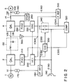
- FIG. 2 Another embodiment of the present invention will be described hereinafter with reference to Fig. 2.
- the reference numerals in Fig. 2 denote the same parts as in Fig. 8, and a description thereof is omitted.
- a power converter comprises: insulated amplifier 300 for detecting DC voltage Vdc; reference generator 310 for generating output frequency reference E310 until power is restored and control is started after power interruption in response to output signal E300 from amplifier 300 and terminal voltage detection signal E160 of load motor 5; comparator 320 for comparing signal E190 from speed reference generator 190 with output signal E310 from reference generator 310, and detecting their coincidence; changer 330 for generating reference changing signal E330 on the basis of output signal E320 from comparator 320 and signal E180 from voltage failure detector (power interruption detector) 180; and switch 340 for switching reference E190 or E310 to be input to oscillator 220 in response to changing signal E330.
- power interruption detection signal E180 from power interruption detector 180 is supplied to changer 330, and reference switch 340 is switched.
- signal E190 from speed reference setting circuit 190 which is previously used is disconnected, and output signal E310 of reference generator 310 is connected to oscillator 220.
- Terminal voltage (remaining voltage) Vac of load motor 5 is detected by voltage transformer 160, and the speed and voltage phase of load motor 5 are calculated by reference generator 310 in response to detection signal E160.
- DC voltage detection signal E300 from insulated amplifier 300 is compared with a speed signal (E311G in Fig. 3) of load motor 5 calculated in reference generator 310, and reference signal E310 corresponding to the operation frequency of inverter 4, having a predetermined ratio, is supplied to oscillator 220 through switch 340. Therefore, the frequency and phase of inverter 4 are controlled.
- DC voltage Vac of inverters 2 and 4 and terminal voltage Vac of load motor 5 are controlled in accordance with a proportional relationship. With this control, terminal voltage Vac and motor speed of load motor 5 constantly keep a predetermined relationship, and the magnetic flux of load motor 5 is always kept at a predetermined value during power interruption.
- power restoration detection signal E180 is supplied to phase controller 210 and voltage controller 200, and these controllers restart control.
- DC voltage control in rectifier 2 is started.
- the DC voltage reference signal supplied to voltage controller 200 is set signal E190 of speed reference setting circuit 190.
- DC voltage Vdc is caused to follow set value E190 of speed reference setting circuit 190 by voltage controller 200.
- reference generator 310 mentioned in the above description for the control during power interruption, controls the frequency and phase of inverter 4 to decrease DC voltage Vdc, thus increasing input current Iac to load motor 5.
- Fig. 3 shows an arrangement of typical reference generator 310 in Fig. 2.
- Signal E160 representing terminal voltage Vac of load motor 5 is converted into sine-wave signal E311A having no high-frequency noise through low-pass filter 311A.
- Signal E311A is input to a zero-crossing sensor including resistor R311, inverting amplifier 311B, and diode D311.
- Signal E311A is converted into rectangular-wave signal E311B having a duty ratio of 50% (phase angle: 180°) by the zero-crossing sensor.
- Pulse signal E311C is generated at a rate of one pulse per period (e.g., 50 ms) of terminal voltage Vac, and is input to hold circuit (latch circuit) 311F. Hold circuit 311F outputs reset pulse RP for every input of pulse signal E311C.
- clock pulse E311D having a period (e.g., 0.05 ms) much shorter than terminal voltage Vac is input to counter 311E from pulse oscillator 311D.
- Counter 311E is reset in response to reset pulse RP, and counts clock pulse E311D generated during one period of reset pulse RP.
- Count result E311E is temporarily stored in hold circuit 311F.
- hold circuit 311F stores data E311F obtained by digitizing one period of terminal voltage Vac (one period of reset pulse RP) by a count value of clock pulse E311D.
- Period data E311F is updated every period of terminal voltage Vac, and converted into analog signal E311G by D/A converter 311G.
- This signal E311G includes phase or frequency data of voltage Vac of motor 5.
- circuit elements 311A to 311G constitute a means for detecting a period or frequency of terminal voltage Vac of load motor 5.
- the above-mentioned analog signal E311G is input to inverting amplifier 312A through resistor R312A.
- Amplifier 312A receives signal E300 representing DC output voltage Vdc of rectifier 2 through resistor R312B.
- Output E312A from amplifier 312A is subjected to negative feedback to its input terminal through capacitor C312 and resistor R312.
- a proportional integrating circuit for comparing analog signal E311G with DC voltage signal E300 and proportionally integrating and amplifying the comparison result is constituted.
- a series circuit of opposed-connected constant voltage diodes Z312A and Z312B which is connected in parallel with a series circuit of capacitor C312 and resistor R312 is employed to obtain a limiter function for limiting the voltage level of output E312A from amplifier 312A to a predetermined value or less.
- Output E312A from amplifier 312A is input to inverting amplifier 312B through resistor R312C.
- Amplifier 312B also receives the above-mentioned analog signal E311G through resistor R312D.
- Output E310 from amplifier 312B is subjected to negative feedback to its input terminal through resistor R312E.
- an adder for adding analog signal E311G to output E312A is constituted.
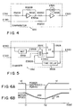
- Fig. 4 shows an arrangement of typical comparator 320 in Fig. 2.
- Output E310 from reference generator 310 is input to inverting amplifier 320A through resistor R320A.
- Output E320A from amplifier 320A is subjected to negative feedback to its input terminal through resistor R320B.
- Output E320A is input to inverting amplifier 320B through resistor R320C.
- Amplifier 320B also receives speed reference set value E190 through resistor R320D.
- the output terminal of amplifier 320B is connected to its input terminal through a cathode-anode path of diode D320.
- Amplifier 320B compares level -E310 with level +190. Amplifier 320B outputs signal E320 set at logic "1" when E190 ⁇ E310, and outputs signal E320 set at logic "0" when E190 > E310.
- Fig. 5 shows an arrangement of typical changer 330 in Fig. 2.
- Output E330 set at logic "1" is delayed by delay circuit 330B by a predetermined time (e.g., about 1 ⁇ s), and serves as delay signal E330B.
- Signal E330B is supplied to the first input terminal of AND gate 330C.
- Signal E320 is input to the second input terminal of AND gate 330C, and signal E330D is input to the third input terminal thereof. (This signal E330D is obtained by inverting the level of output E310 by NOT gate 330D).
- Q output E330 from flip-flop 330A is set at logic "0".
- Switch 340 shown in Fig. 2 is switched in response to logic "0" output E330, and speed reference set value E190 is supplied to oscillator 220 in place of reference generator output E310.
- power interruption detector 180 shown in Fig. 2 may be the same as power interruption detector 6 shown in Fig. 1.
- Figs. 6A and 6B are waveform charts showing a change in DC voltage Vdc in the power converter after power restoration.
- the change in DC voltage Vdc is a function which satisfies, e.g., the following condition:
- the output frequency and phase of the power converter are controlled in accordance with detection signal E310, and DC voltage Vdc is controlled in correspondence with (in proportion to) motor speed N. Therefore, the following effects can be obtained.
Landscapes
- Engineering & Computer Science (AREA)
- Power Engineering (AREA)
- Inverter Devices (AREA)
- Control Of Ac Motors In General (AREA)
Claims (10)
- Leistungskonverter zur Wandlung von Eingangswechselspannung in eine Gleichspannung und zur Wandlung der Gleichspannung in eine Ausgangswechselspannung, an die eine Last (5) angeschlossen ist, wobei der Leistungskonverter folgendes umfaßt:
eine Steuereinrichtung (9-10 in Fig. 1/ 220-230 in Fig. 2) zur Steuerung des Wandlerbetriebs des Leistungskonverters;
eine Gleichspannungsdetektoreinrichtung (11 in Fig. 1/ 300 in Fig 2) zur Erfassung einer Gleichspannung (Vdc) im Gleichspannungskreis, um ein Gleichspannungssignal (E11/ E300) bereitzustellen;
eine erste Referenzgeneratoreinrichtung (12-13 in Fig. 1/ 190 in Fig. 2) zur Generierung einer ersten Referenz (E13/ E300);
eine Ausgangsdetektoreinrichtung (14-15 in Fig. 1/ 160 in Fig. 2) zur Erfassung eines Zustands (Iac, Vac) der Ausgangswechselspannung, um ein Ausgangszustandssignal (E15/ E160) bereitzustellen;
eine zweite Referenzgeneratoreinrichtung (16-17 in Fig. 1/ 310 in Fig. 2) zur Generierung einer zweiten Referenz (E17/ E310) in Reaktion auf das Ausgangszustandssignal (E15/ E160), das von der Ausgangsdetektoreinrichtung bereitgestellt wird;
dadurch gekennzeichnet, daß dieser weiter folgendes umfaßt:
eine Zustandsdetektoreinrichtung (6 in Fig. 1/ 170-180 in Fig. 2) zur Erfassung einer Leistungsunterbrechung als einen Zustand der Eingangswechselspannung, um ein Eingangszustandssignal (E6/ E180) bereitzustellen, wobei der besagte Zustand der Eingangswechselspannung (Vi) von der Zustandsdetektoreinrichtung (6/ 170-180), die eine Sperrung der Ausgangswechselspannung (Vac) anzeigt, als unzulässiger Zustand zu erfassen ist, mit dem die Last (5) nicht kontinuierlich betrieben werden kann; und
eine Wahleinrichtung (18 in Fig. 1/ 330-340 in Fig. 2) zum Anlegen der zweiten Referenz (E17/ E310) an die Steuereinrichtung, wenn die Zustandsdetektoreinrichtung ein Eingangszustandssignal (E6/ E180) abgibt, wodurch eine Fortsetzung des Konverterbetriebs auch dann erfolgt, wenn sich die Ausgangswechselspannung (Vac) im unzulässigen Zustand befindet. - Leistungskonverter nach Anspruch 1, dadurch gekennzeichnet, daß die erste Referenzgeneratoreinrichtung (12X-13) die erste Referenz (E13) entsprechend einer Differenz zwischen dem Gleichspannungssignal (E11) und einer gegebenen Gleichspannungsreferenz (E12) generiert.
- Leistungskonverter nach Anspruch 2, dadurch gekennzeichnet, daß die Ausgangsdetektoreinrichtung (14-15) einen an die Last (5) abgegebenen Ausgangsstrom (Iac) erfaßt und ein Ausgangsstromsignal (E15) bereitstellt, welches das Ausgangszustandssignal (E15/ E160) bildet.
- Leistungskonverter nach Anspruch 3, dadurch gekennzeichnet, daß die zweite Referenzgeneratoreinrichtung (16X-17) auf eine gegebene Wechselstromreferenz (E16) reagiert und die zweite Referenz (E17) entsprechend einer Differenz zwischen dem Ausgangsstromsignal (E15) und einer gegebenen Wechselstromreferenz (E16) generiert.
- Leistungskonverter nach Anspruch 4, dadurch gekennzeichnet, daß die Zustandsdetektoreinrichtung (6) eine Unterbrechung der Eingangswechselspannung erfaßt und ein Versorgungsunterbrechungssignal (E6) bereitstellt, welches das Eingangszustandssignal (E6/ E160) bildet.
- Leistungskonverter nach Anspruch 5, dadurch gekennzeichnet, daß dieser weiterhin Referenzgeneratoreinrichtungen (7-8) zur Generierung einer Frequenzreferenz (f*) und einer Spannungsreferenz (V*) umfaßt, und wobei die Wahleinrichtung (18) die Frequenzreferenz (f*) und die Spannungsreferenz (V*) an die Steuereinrichtung (9-10) legt, wenn keine Unterbrechung der Eingangswechselspannung vorliegt, während bei Vorliegen des Versorgungsunterbrechungssignals (E16) anstelle der Frequenzreferenz (f*) und der Spannungsreferenz (V*) die erste Referenz (E13) und die zweite Referenz (E17) an die Steuereinrichtung (9-10) gelegt werden.
- Leistungskonverter nach Anspruch 1, dadurch gekennzeichnet, daß die zweite Referenzgeneratoreinrichtung (310) die zweite Referenz (E310) entsprechend dem Ausgangszustandssignal (E160) und dem Gleichspannungssignal (E100) generiert.
- Leistungskonverter nach Anspruch 7, gekennzeichnet durch weiterhin eine Vergleichereinrichtung (320), die mit der ersten Referenzgeneratoreinrichtung (190) und der zweiten Referenzgeneratoreinrichtung (310) gekoppelt ist, um die zweite Referenz (E310) mit der ersten Referenz (E190) zu vergleichen und um einen Vergleichsausgang (E320) bereitzustellen.
- Leistungskonverter nach Anspruch 8, dadurch gekennzeichnet, daß die Wahleinrichtung (330-340) die erste Referenz (E190) an die Steuereinrichtung (220-230) anlegt, wenn keine wesentliche Spannungsreduzierung der Eingangswechselspannung vorliegt, während bei Vorliegen des Eingangszustandssignals (E180) in Reaktion auf den Vergleichsausgang (E320) anstelle der ersten Referenz (E190) die zweite Referenz (E310) an die Steuerung (220-230) gelegt wird.
- Leistungskonverter nach einem beliebigen der Ansprüche 1 bis 9, dadurch gekennzeichnet, daß die zweite Referenzgeneratoreinrichtung (310) folgendes umfaßt:
eine Frequenzdetektoreinrichtung (311) zur Erfassung der Frequenz einer an die Last (5) abgegebenen Ausgangswechselspannung (Vac), und zur Bereitstellung eines Frequenzsignals (E311G) mit einem Signalpegel entsprechend der Frequenz der Ausgangswechselspannung (Vac); und
eine Einrichtung (312), die mit der Frequenzdetektoreinrichtung (311) und der Gleichspannungsdetektoreinrichtung (300) gekoppelt ist, um das Frequenzsignal (E311G) mit dem Gleichspannungssignal (E300) zu kombinieren, um das zweite Referenzsignal (E310) bereitzustellen.
Applications Claiming Priority (4)
| Application Number | Priority Date | Filing Date | Title |
|---|---|---|---|
| JP63065651A JPH01243884A (ja) | 1988-03-22 | 1988-03-22 | 電力変換装置及びその制御方法 |
| JP65651/88 | 1988-03-22 | ||
| JP83145/88 | 1988-04-06 | ||
| JP63083145A JPH01259791A (ja) | 1988-04-06 | 1988-04-06 | 電力変換装置 |
Publications (3)
| Publication Number | Publication Date |
|---|---|
| EP0334319A2 EP0334319A2 (de) | 1989-09-27 |
| EP0334319A3 EP0334319A3 (en) | 1990-04-04 |
| EP0334319B1 true EP0334319B1 (de) | 1994-05-11 |
Family
ID=26406793
Family Applications (1)
| Application Number | Title | Priority Date | Filing Date |
|---|---|---|---|
| EP89105132A Expired - Lifetime EP0334319B1 (de) | 1988-03-22 | 1989-03-22 | Leistungskonverter und Steuerverfahren |
Country Status (3)
| Country | Link |
|---|---|
| US (1) | US4876637A (de) |
| EP (1) | EP0334319B1 (de) |
| DE (1) | DE68915195T2 (de) |
Families Citing this family (37)
| Publication number | Priority date | Publication date | Assignee | Title |
|---|---|---|---|---|
| AT396638B (de) * | 1990-02-28 | 1993-10-25 | Elin Energieanwendung | Regelungssystem für einen spannungszwischenkreisumrichter der eine asynchronmaschine speist |
| FI86784C (fi) * | 1990-03-13 | 1992-10-12 | Kone Oy | Foerfarande och anordning foer bromsning av en av en frekvenskonverter matad kortsluten asynkronmotor i en hiss i en felsituation |
| JP2996542B2 (ja) * | 1991-07-03 | 2000-01-11 | 本田技研工業株式会社 | インバータ式電源装置 |
| JP2934345B2 (ja) * | 1991-09-06 | 1999-08-16 | 三菱電機株式会社 | 誘導電動機の制御装置 |
| JPH0638575A (ja) * | 1992-07-17 | 1994-02-10 | Honda Motor Co Ltd | 交流電動機のトルク制御装置 |
| JPH0654586A (ja) * | 1992-07-28 | 1994-02-25 | Fuji Electric Co Ltd | 同期電動機駆動用インバータの瞬停再起動装置 |
| US5631812A (en) * | 1992-10-06 | 1997-05-20 | Fanuc Ltd. | Motor drive control method |
| US5481451A (en) * | 1992-10-30 | 1996-01-02 | Arex Electronics Corporation | AC-to-AC power inverter apparatus functioning without smoothing capacitor, and control method thereof |
| GB9314262D0 (en) * | 1993-07-09 | 1993-08-18 | Sgs Thomson Microelectronics | A multistandard ac/dc converter embodying mains voltage detection |
| JPH0835712A (ja) * | 1994-07-26 | 1996-02-06 | Fujitsu General Ltd | 空気調和機の制御装置 |
| US5672950A (en) * | 1994-08-16 | 1997-09-30 | Itt Corporation | Voltage, phase and frequency control by miniature inverter system |
| US5583412A (en) * | 1995-02-28 | 1996-12-10 | Allen-Bradley Company, Inc. | Apparatus and method for controlling the deceleration of an electric motor |
| US5650709A (en) * | 1995-03-31 | 1997-07-22 | Quinton Instrument Company | Variable speed AC motor drive for treadmill |
| JP2863833B2 (ja) * | 1996-09-18 | 1999-03-03 | 岡山大学長 | アクティブコモンモードキャンセラ |
| US5801522A (en) * | 1996-09-26 | 1998-09-01 | Compaq Computer Corporation | Power limit circuit for computer system |
| JP3372436B2 (ja) * | 1996-11-28 | 2003-02-04 | オークマ株式会社 | インバータの制御装置 |
| KR100229507B1 (ko) * | 1997-02-21 | 1999-11-15 | 윤종용 | 이상전압 보호기능을 갖는 스위칭 모드 전원공급기 |
| JP3722963B2 (ja) * | 1997-10-03 | 2005-11-30 | 三菱電機株式会社 | 電力変換装置 |
| JP3206733B2 (ja) * | 1997-11-25 | 2001-09-10 | 株式会社三社電機製作所 | 直流電源装置 |
| AT409803B (de) * | 1999-06-16 | 2002-11-25 | Fronius Schweissmasch Prod | Verfahren zum erkennen einer an einen wechselrichter bedarfsweise anschaltbaren last und entsprechendes lasterkennungssystem |
| US6639467B1 (en) * | 2003-01-27 | 2003-10-28 | Gene E. Lightner | Alternating current derived from direct current |
| KR100639447B1 (ko) * | 2003-04-14 | 2006-10-26 | 마츠시타 덴끼 산교 가부시키가이샤 | 모터 구동 장치, 압축기, 공기 조화기, 냉장고, 전기 세탁기, 송풍기, 전기 청소기, 전기 건조기 및 열 펌프 급탕기 |
| WO2005027301A1 (en) * | 2003-09-16 | 2005-03-24 | General Electric Company | Method for operating a frequency converter of a generator |
| GB0326070D0 (en) * | 2003-11-07 | 2003-12-10 | Newage Int Ltd | An AC power generating system |
| CN1684348B (zh) * | 2004-04-16 | 2010-10-20 | 深圳赛意法微电子有限公司 | 具有便于驱动器与变换器电路配合使用的控制接口的驱动器 |
| US7116067B2 (en) * | 2004-09-21 | 2006-10-03 | Honeywell International Inc. | Power converter controlling apparatus and method providing ride through capability during power interruption in a motor drive system |
| KR100724489B1 (ko) * | 2005-05-11 | 2007-06-04 | 엘에스산전 주식회사 | 인버터 입력 전압 변동 보상 장치 및 방법 |
| DE102005042615A1 (de) * | 2005-09-07 | 2007-03-08 | Franz Haimer Maschinenbau Kg | Schaltung, Schrumpfbefestigung und Verfahren zur Regelung |
| US7279865B2 (en) * | 2005-09-20 | 2007-10-09 | Rockwell Automation Technologies, Inc. | Method and apparatus for monitoring motor status using induced motor voltage |
| CN101529709B (zh) * | 2006-10-19 | 2012-06-27 | 三菱电机株式会社 | 电力变换装置 |
| JP4708495B1 (ja) * | 2010-01-28 | 2011-06-22 | ファナック株式会社 | 停電検出機能を有するモータ駆動装置 |
| US8917041B2 (en) * | 2010-07-12 | 2014-12-23 | Panasonic Corporation | Phase-shift detection device, motor drive device, brushless motor, and phase-shift detection method |
| KR102213786B1 (ko) * | 2014-10-15 | 2021-02-08 | 엘에스일렉트릭(주) | 고압인버터 재기동 장치 |
| US9800133B2 (en) * | 2016-03-22 | 2017-10-24 | Infineon Technologies Ag | Active common mode cancellation |
| CN110637412B (zh) * | 2017-05-09 | 2023-03-24 | 阿尔卑斯阿尔派株式会社 | 带旋转角度检测器的电动机、电动机的旋转角度检测器及探测旋转角度检测器的故障的方法 |
| US12304318B2 (en) * | 2021-08-26 | 2025-05-20 | Hamilton Sundstrand Corporation | Motor speed measurement systems |
| US12282045B2 (en) | 2022-12-02 | 2025-04-22 | Infineon Technologies Ag | Common mode evaluation in a differential galvanic isolation signal transmission circuit |
Family Cites Families (9)
| Publication number | Priority date | Publication date | Assignee | Title |
|---|---|---|---|---|
| JPS5594583A (en) * | 1979-01-10 | 1980-07-18 | Hitachi Ltd | Frequency converter and its controlling method |
| DE3029358A1 (de) * | 1980-08-01 | 1982-03-11 | Siemens AG, 1000 Berlin und 8000 München | Einrichtung zur ueberbrueckung von kurzzeitigen netzausfaellen bei spannungszwischenkreis-umrichtern |
| US4376968A (en) * | 1981-02-13 | 1983-03-15 | Borg-Warner Corporation | Protection system for immunizing an inverter system against A-C line voltage disturbances |
| CA1224245A (en) * | 1984-03-02 | 1987-07-14 | Suzuo Saito | Power converter for ac load |
| JPS61102172A (ja) * | 1984-10-23 | 1986-05-20 | Hitachi Ltd | 自己消弧素子利用電流形コンバ−タ装置 |
| US4620296A (en) * | 1984-11-29 | 1986-10-28 | Dana Corporation | Protection system for immunizing a controlled d-c power supply against a-c line voltage interruptions |
| DE3527844A1 (de) * | 1985-07-31 | 1987-02-12 | Licentia Gmbh | Schaltungsanordnung zur frequenzverstellung eines gleichspannungs-zwischenkreisumrichters bei konstanter ausgangsspannung |
| JPS62104493A (ja) * | 1985-10-30 | 1987-05-14 | Toshiba Corp | 交流電動機の駆動装置 |
| JPS6356183A (ja) * | 1986-08-22 | 1988-03-10 | Nippon Oochisu Elevator Kk | エレベ−タ駆動用インバ−タ |
-
1989
- 1989-03-21 US US07/326,647 patent/US4876637A/en not_active Expired - Fee Related
- 1989-03-22 EP EP89105132A patent/EP0334319B1/de not_active Expired - Lifetime
- 1989-03-22 DE DE68915195T patent/DE68915195T2/de not_active Expired - Fee Related
Also Published As
| Publication number | Publication date |
|---|---|
| EP0334319A3 (en) | 1990-04-04 |
| EP0334319A2 (de) | 1989-09-27 |
| US4876637A (en) | 1989-10-24 |
| DE68915195D1 (de) | 1994-06-16 |
| DE68915195T2 (de) | 1994-08-18 |
Similar Documents
| Publication | Publication Date | Title |
|---|---|---|
| US4876637A (en) | Power converter and method of controlling the same | |
| US4319177A (en) | Operation control apparatus for AC motors | |
| EP0166052B1 (de) | Verfahren und System zur Wiedereinschaltung von Umformern auf rotierende Motoren | |
| AU589803B2 (en) | Alternating current motor control apparatus | |
| EP0165020B1 (de) | Leistungswandler für eine Wechselstromlast | |
| KR900007695B1 (ko) | 동기모터구동용 전력변환기의 제어방법과 그 장치 | |
| EP2017951B1 (de) | Steuerung eines Wiederstartens eines Drehstromantriebs | |
| WO2019123627A1 (ja) | 電動機駆動装置 | |
| JPH067754B2 (ja) | 誘導電動機の制御装置 | |
| JPS6122556B2 (de) | ||
| KR100269450B1 (ko) | 모터구동제어장치 | |
| JP3836271B2 (ja) | モータ制御装置 | |
| JPS6322156B2 (de) | ||
| JP2689601B2 (ja) | 回生機能付電力変換装置 | |
| JPH06245565A (ja) | 電圧形インバータ装置の回生制御装置 | |
| JPH10304669A (ja) | Pwmコンバータ装置 | |
| JP2001028880A (ja) | 電力変換装置ならびにこれを用いた発電装置および駆動装置 | |
| JP2002272181A (ja) | 電力変換装置 | |
| JPH07194167A (ja) | ミシン用モータ駆動装置 | |
| JP2592977B2 (ja) | 電力変換装置 | |
| JP2001286155A (ja) | 電力変換装置 | |
| JPH0442913B2 (de) | ||
| JPH0341023B2 (de) | ||
| KR830001379B1 (ko) | 정류 장해를 보호받게 한 다상(多相) 하이브리드 정류브릿지 | |
| JPS63148880A (ja) | インバ−タの停電時制御装置 |
Legal Events
| Date | Code | Title | Description |
|---|---|---|---|
| PUAI | Public reference made under article 153(3) epc to a published international application that has entered the european phase |
Free format text: ORIGINAL CODE: 0009012 |
|
| 17P | Request for examination filed |
Effective date: 19890419 |
|
| AK | Designated contracting states |
Kind code of ref document: A2 Designated state(s): CH DE FR GB LI SE |
|
| PUAL | Search report despatched |
Free format text: ORIGINAL CODE: 0009013 |
|
| AK | Designated contracting states |
Kind code of ref document: A3 Designated state(s): CH DE FR GB LI SE |
|
| 17Q | First examination report despatched |
Effective date: 19920601 |
|
| RBV | Designated contracting states (corrected) |
Designated state(s): DE FR GB SE |
|
| GRAA | (expected) grant |
Free format text: ORIGINAL CODE: 0009210 |
|
| AK | Designated contracting states |
Kind code of ref document: B1 Designated state(s): DE FR GB SE |
|
| REF | Corresponds to: |
Ref document number: 68915195 Country of ref document: DE Date of ref document: 19940616 |
|
| ET | Fr: translation filed | ||
| EAL | Se: european patent in force in sweden |
Ref document number: 89105132.8 |
|
| PGFP | Annual fee paid to national office [announced via postgrant information from national office to epo] |
Ref country code: GB Payment date: 19950315 Year of fee payment: 7 |
|
| PLBE | No opposition filed within time limit |
Free format text: ORIGINAL CODE: 0009261 |
|
| STAA | Information on the status of an ep patent application or granted ep patent |
Free format text: STATUS: NO OPPOSITION FILED WITHIN TIME LIMIT |
|
| 26N | No opposition filed | ||
| PG25 | Lapsed in a contracting state [announced via postgrant information from national office to epo] |
Ref country code: GB Effective date: 19960322 |
|
| GBPC | Gb: european patent ceased through non-payment of renewal fee |
Effective date: 19960322 |
|
| REG | Reference to a national code |
Ref country code: FR Ref legal event code: D6 |
|
| PGFP | Annual fee paid to national office [announced via postgrant information from national office to epo] |
Ref country code: DE Payment date: 19991231 Year of fee payment: 12 |
|
| PGFP | Annual fee paid to national office [announced via postgrant information from national office to epo] |
Ref country code: SE Payment date: 20000307 Year of fee payment: 12 |
|
| PGFP | Annual fee paid to national office [announced via postgrant information from national office to epo] |
Ref country code: FR Payment date: 20000310 Year of fee payment: 12 |
|
| PG25 | Lapsed in a contracting state [announced via postgrant information from national office to epo] |
Ref country code: SE Free format text: LAPSE BECAUSE OF NON-PAYMENT OF DUE FEES Effective date: 20010323 |
|
| EUG | Se: european patent has lapsed |
Ref document number: 89105132.8 |
|
| PG25 | Lapsed in a contracting state [announced via postgrant information from national office to epo] |
Ref country code: FR Free format text: LAPSE BECAUSE OF NON-PAYMENT OF DUE FEES Effective date: 20011130 |
|
| REG | Reference to a national code |
Ref country code: FR Ref legal event code: ST |
|
| PG25 | Lapsed in a contracting state [announced via postgrant information from national office to epo] |
Ref country code: DE Free format text: LAPSE BECAUSE OF NON-PAYMENT OF DUE FEES Effective date: 20020101 |