EP0333902A1 - Vorrichtung zum Aufbringen eines thermoplastischen, hochpolymeren Werkstoffes, insbesondere eines Klebstoffes - Google Patents
Vorrichtung zum Aufbringen eines thermoplastischen, hochpolymeren Werkstoffes, insbesondere eines Klebstoffes Download PDFInfo
- Publication number
- EP0333902A1 EP0333902A1 EP88104676A EP88104676A EP0333902A1 EP 0333902 A1 EP0333902 A1 EP 0333902A1 EP 88104676 A EP88104676 A EP 88104676A EP 88104676 A EP88104676 A EP 88104676A EP 0333902 A1 EP0333902 A1 EP 0333902A1
- Authority
- EP
- European Patent Office
- Prior art keywords
- feed channel
- channel
- rotary element
- application head
- outlet opening
- Prior art date
- Legal status (The legal status is an assumption and is not a legal conclusion. Google has not performed a legal analysis and makes no representation as to the accuracy of the status listed.)
- Withdrawn
Links
Images

Classifications
-
- B—PERFORMING OPERATIONS; TRANSPORTING
- B05—SPRAYING OR ATOMISING IN GENERAL; APPLYING FLUENT MATERIALS TO SURFACES, IN GENERAL
- B05B—SPRAYING APPARATUS; ATOMISING APPARATUS; NOZZLES
- B05B9/00—Spraying apparatus for discharge of liquids or other fluent material, without essentially mixing with gas or vapour
- B05B9/002—Spraying apparatus for discharge of liquids or other fluent material, without essentially mixing with gas or vapour incorporating means for heating or cooling, e.g. the material to be sprayed
-
- B—PERFORMING OPERATIONS; TRANSPORTING
- B05—SPRAYING OR ATOMISING IN GENERAL; APPLYING FLUENT MATERIALS TO SURFACES, IN GENERAL
- B05B—SPRAYING APPARATUS; ATOMISING APPARATUS; NOZZLES
- B05B3/00—Spraying or sprinkling apparatus with moving outlet elements or moving deflecting elements
- B05B3/02—Spraying or sprinkling apparatus with moving outlet elements or moving deflecting elements with rotating elements
Definitions
- the invention relates to a device for applying a thermoplastic, high polymer material, in particular an adhesive, to a substrate of the type specified in the preamble of claim 1.
- the basic structure of such a device is apparent, for example, from DE-GM 85 34 594 and has an application head, a feed channel for the liquefied material in the application head, a nozzle-like outlet opening at the end of the feed channel and a valve arrangement for opening and closing the feed channel or the Outlet opening.
- a gas generally air
- the application head is supplied to the application head so that the emerging application mass is atomized by the pressurized gas and applied to the substrate to be coated in the form of a spray curtain or mist .
- the invention is therefore based on the object of creating a device for applying a thermoplastic, high-polymer material, in particular an adhesive, of the type specified, in which the disadvantages mentioned above do not occur.
- a device is to be proposed with which the applied application pattern can be changed and modified in a simple manner.
- a rotatably mounted rotary element is integrated in the application head with a channel aligned with the feed channel and the outlet opening, so that different application patterns can be achieved by appropriate design of the outlet angle of the outlet opening. If the element is rotated, in particular pneumatically, by means of a drive device, circular application patterns can be generated, for example, if the outlet opening runs at an angle to the vertical, about which the element rotates. The rotation results in an extension of the emerging mass and a kind of spray tint.
- the rotary element For the pneumatic rotation of the rotary element, it can be provided with a screw, past which a gas, in particular an air stream, flows and thereby rotates the screw and thus also the rotary element.
- the air pressure or volume can be adjusted accordingly Rotation speed of the element so that the range of the application mass emerging from the outlet opening and finally the diameter of the application pattern generated are set.
- the rotary element itself can also be removed very simply and quickly and exchanged for an element with a differently configured outlet opening, as a result of which further application patterns can be realized.
- thermoplastic high-polymer material namely an adhesive
- a substrate not shown
- a liquefaction device 12 which is known, for example, from DE-OS 2 836 545 Has structure.
- the top of the liquefaction device 12 is provided with a filler cap 14 for the adhesive to be refilled.
- the liquefaction device 12 is connected via a heat-insulated hose 16 to an application head 18, on the underside of which a nozzle 20 is provided for applying the adhesive to a material web (not shown) to be coated with the adhesive.
- the hose 16 has a connection piece 22 at its inlet end and a connection piece 24 at its outlet end, which are fastened to the liquefaction device 12 or the application head 18 by corresponding counterparts.
- the connections are surrounded by a heat-insulating sleeve.
- two lines are led through the outer wall thereof, namely a supply line 26 connected to a heating tape inside the hose 16 and a control line 28.
- the application head 18 has a body 30 which is connected at its lower end to the outlet nozzle 20 and at its upper end to a connection 32 for compressed air, which is used for actuating its valve arrangement in the application head 18, which is yet to be explained.
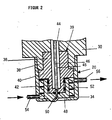
- the part of the application head 18 of interest here, namely the outlet nozzle 20, can be seen in FIG. 2.
- the outlet nozzle 20 has a cap-shaped housing 34 which is screwed via an internal thread onto the external thread of a correspondingly shaped extension 36 of the body 30.
- the extension 36 has a cylindrical bore in which a corresponding extension 38 of an intermediate piece 39 is arranged; a widening 40 adjoins the extension 38 of the intermediate piece 39, the outer diameter of which is somewhat smaller than the outer diameter of the sleeve 36.
- the intermediate piece 39 that is to say the widening 40, merges into a cylindrical end piece 42.
- the intermediate piece 39 with the parts 38, 40, 42 can be screwed into the housing 30, namely with its attachment 38.
- the housing 30 has a feed channel 44 for the liquefied adhesive, which merges into a corresponding feed channel 45 with the same diameter in the intermediate piece 39. At the lower end of the intermediate piece 39, that is to say in the area of the extension 42, the diameter of the channel 45 in the intermediate piece 39 is reduced.
- a reciprocating valve needle 46 is arranged in the channel 44, 45 in the housing 30 and the intermediate piece 39, the lower end of which, as shown in FIG. 2, rests on the channel constriction at the lower end and thereby blocks the channel 45.
- valve needle 46 is connected to a stepped piston 48 (see FIG. 1) which is actuated pneumatically, that is to say pushed back and forth, to bring the needle 46 into or out of contact with the constriction of the feed channel 45 and thereby to open or close the feed channel 45.
- a cap-shaped rotary element 48 with a U-cross section is integrated into the lower end of the outlet nozzle 20, the inner surfaces of which, ie the inner surfaces of the side walls and the bottom, bear against the corresponding counter surfaces of the attachment 42.
- the upper edges of the side walls bear against the widening 40 from below.
- the pivot bearings indicated in black are arranged between these surfaces.
- the narrowed channel 45 in the extension 42 continues through the bottom of the rotary element 48 and then bends slightly towards its outlet 50, so that the outlet 50 is arranged obliquely with respect to the feed channel 44.
- the lateral outer wall of the rotating element 48 is designed with a circumferential screw 52 which serves to guide the flow and whose turns can be seen from FIG. 2.
- the rotating element 48 and the worm 52 can rotate freely in the space between the cap-shaped element 34 and the shoulder.
- the cap 34 is provided with a compressed air inlet 54 and on the opposite side with a compressed air outlet 56; the direction of flow of the compressed air is indicated by the arrows.
- the intermediate piece 39 is screwed into the lower end of the body 30.
- the rotating element 48 is inserted freely rotatable, and finally the cap 34 is screwed onto the intermediate piece 39 and onto the extension 36 of the body 30.
- the rotating element 48 is fixed in a freely rotatable manner about a vertical axis.
- the liquefied adhesive from the liquefaction device 12 is fed to the application head 18 via the hose 16, wherein it is present in the feed channel 44 at a certain pressure.
- the feed channel 44, 45 and thus the outlet 50 are blocked, so that no adhesive can escape.
- the stepped piston 48 of the valve needle 46 is actuated pneumatically and thereby shifted upwards as shown in FIG. 2, so that the feed channel 44, 45 and thus the outlet opening 50 are released.
- Fig. 1 the compressed air flows for the pneumatic actuation of the valve needle 46 are indicated by arrows.
- an electromagnetic valve 58 is shown, which serves to control the compressed air supply to the stepped piston 48.
- the rotating element 48 can also be removed as a whole and exchanged for another rotating element 48 with a different configuration of the outlet 50, in particular with regard to the angle to the feed channel 44, 45.
- the liquefied adhesive in the feed channel 44, 45 can be atomized by means of compressed air be, whereby the application head 18 is converted into a spray head.
- the air required for spraying can be supplied separately via the intermediate piece 39 by means of a further channel which opens into the outlet 50.
- this air via the rotating element 48, either via a separate duct or as "branch air", i.e. part of the air supplied via the inlet 54 is used to spray the adhesive.
- the additional air nozzles known from DE-GM 8 534 594 can also be integrated into the application head 18.
Landscapes
- Nozzles (AREA)
- Application Of Or Painting With Fluid Materials (AREA)
- Coating Apparatus (AREA)
- Adhesives Or Adhesive Processes (AREA)
Priority Applications (4)
| Application Number | Priority Date | Filing Date | Title |
|---|---|---|---|
| EP88104676A EP0333902A1 (de) | 1988-03-23 | 1988-03-23 | Vorrichtung zum Aufbringen eines thermoplastischen, hochpolymeren Werkstoffes, insbesondere eines Klebstoffes |
| DE8803938U DE8803938U1 (de) | 1988-03-23 | 1988-03-23 | Vorrichtung zum Aufbringen eines thermoplastischen, hochpolymeren Werkstoffes, insbesondere eines Klebstoffes |
| US07/311,309 US4995558A (en) | 1988-03-23 | 1989-02-16 | Apparatus for applying a thermoplastic high-polymer material, in particular an adhesive, to a substrate |
| JP1073676A JP2680112B2 (ja) | 1988-03-23 | 1989-03-23 | 基板に熱可塑性高重合材料を塗布する装置 |
Applications Claiming Priority (1)
| Application Number | Priority Date | Filing Date | Title |
|---|---|---|---|
| EP88104676A EP0333902A1 (de) | 1988-03-23 | 1988-03-23 | Vorrichtung zum Aufbringen eines thermoplastischen, hochpolymeren Werkstoffes, insbesondere eines Klebstoffes |
Publications (1)
| Publication Number | Publication Date |
|---|---|
| EP0333902A1 true EP0333902A1 (de) | 1989-09-27 |
Family
ID=8198836
Family Applications (1)
| Application Number | Title | Priority Date | Filing Date |
|---|---|---|---|
| EP88104676A Withdrawn EP0333902A1 (de) | 1988-03-23 | 1988-03-23 | Vorrichtung zum Aufbringen eines thermoplastischen, hochpolymeren Werkstoffes, insbesondere eines Klebstoffes |
Country Status (3)
| Country | Link |
|---|---|
| US (1) | US4995558A (ja) |
| EP (1) | EP0333902A1 (ja) |
| JP (1) | JP2680112B2 (ja) |
Cited By (3)
| Publication number | Priority date | Publication date | Assignee | Title |
|---|---|---|---|---|
| EP0367985A2 (en) * | 1988-11-07 | 1990-05-16 | Nordson Corporation | Nozzle attachment for an adhesive spray gun |
| US5065943A (en) * | 1990-09-06 | 1991-11-19 | Nordson Corporation | Nozzle cap for an adhesive dispenser |
| US5169071A (en) * | 1990-09-06 | 1992-12-08 | Nordson Corporation | Nozzle cap for an adhesive dispenser |
Families Citing this family (1)
| Publication number | Priority date | Publication date | Assignee | Title |
|---|---|---|---|---|
| GB2348384A (en) * | 1999-04-01 | 2000-10-04 | Prodef Engineering Limited | Adhesive applicator and machine for applying adhesive |
Citations (3)
| Publication number | Priority date | Publication date | Assignee | Title |
|---|---|---|---|---|
| BE544969A (ja) * | ||||
| DE898413C (de) * | 1950-10-17 | 1953-11-30 | Chiron Werke G M B H | Farbverteiler mit Turbinenantrieb fuer Farb-Spritzpistolen |
| DE1208663B (de) * | 1956-04-27 | 1966-01-05 | Grace W R & Co | Spritzeinrichtung zum Auftragen von Dichtungsmasse in Kreisform |
Family Cites Families (7)
| Publication number | Priority date | Publication date | Assignee | Title |
|---|---|---|---|---|
| US1876607A (en) * | 1932-09-13 | Cleaning machine | ||
| US2964246A (en) * | 1956-04-27 | 1960-12-13 | Grace W R & Co | Gasket applying machine |
| DE2836545C2 (de) * | 1978-08-21 | 1984-11-08 | Fa. Henning J. Claassen, 2120 Lüneburg | Gerät zum Verflüssigen von Schmelzmassen, insbesondere Schmelzklebestoffen |
| DE3419964C2 (de) * | 1984-05-29 | 1986-04-17 | Alfred Kärcher GmbH & Co, 7057 Winnenden | Spritzkopf eines Hochdruckreinigungsgerätes |
| JPS6238257A (ja) * | 1985-08-09 | 1987-02-19 | R D Kosan Kk | 超高圧水噴射装置 |
| DE8534594U1 (de) * | 1985-12-09 | 1986-02-06 | Claassen, Henning J., 2120 Lüneburg | Sprühkopf zum Versprühen eines thermoplastischen Kunststoffes, insbesondere eines Schmelzklebstoffes |
| DE3623368C2 (de) * | 1986-07-11 | 1993-12-02 | Kaercher Gmbh & Co Alfred | Rotordüse für ein Hochdruckreinigungsgerät |
-
1988
- 1988-03-23 EP EP88104676A patent/EP0333902A1/de not_active Withdrawn
-
1989
- 1989-02-16 US US07/311,309 patent/US4995558A/en not_active Expired - Fee Related
- 1989-03-23 JP JP1073676A patent/JP2680112B2/ja not_active Expired - Fee Related
Patent Citations (3)
| Publication number | Priority date | Publication date | Assignee | Title |
|---|---|---|---|---|
| BE544969A (ja) * | ||||
| DE898413C (de) * | 1950-10-17 | 1953-11-30 | Chiron Werke G M B H | Farbverteiler mit Turbinenantrieb fuer Farb-Spritzpistolen |
| DE1208663B (de) * | 1956-04-27 | 1966-01-05 | Grace W R & Co | Spritzeinrichtung zum Auftragen von Dichtungsmasse in Kreisform |
Cited By (5)
| Publication number | Priority date | Publication date | Assignee | Title |
|---|---|---|---|---|
| EP0367985A2 (en) * | 1988-11-07 | 1990-05-16 | Nordson Corporation | Nozzle attachment for an adhesive spray gun |
| EP0367985A3 (en) * | 1988-11-07 | 1990-08-08 | Nordson Corporation | Nozzle attachment for an adhesive spray gun |
| AU620920B2 (en) * | 1988-11-07 | 1992-02-27 | Nordson Corporation | Nozzle attachment for an adhesive spray gun |
| US5065943A (en) * | 1990-09-06 | 1991-11-19 | Nordson Corporation | Nozzle cap for an adhesive dispenser |
| US5169071A (en) * | 1990-09-06 | 1992-12-08 | Nordson Corporation | Nozzle cap for an adhesive dispenser |
Also Published As
| Publication number | Publication date |
|---|---|
| JPH01284352A (ja) | 1989-11-15 |
| JP2680112B2 (ja) | 1997-11-19 |
| US4995558A (en) | 1991-02-26 |
Similar Documents
| Publication | Publication Date | Title |
|---|---|---|
| DE69530275T2 (de) | Spritzpistole mit einstellbarem Abgabeventil | |
| EP2451586B1 (de) | Farbspritzpistole | |
| EP1880771B1 (de) | Spritzpistole | |
| DE69420186T3 (de) | Vernebler | |
| DE3906219C2 (de) | Regulierventil | |
| DE9416015U1 (de) | Düsenanordnung für eine Farbspritzpistole | |
| EP0710506B1 (de) | Düsenanordnung für eine Farbspritzpistole | |
| DE3024386A1 (de) | Farbspritzkanone | |
| DE2737680C3 (de) | Spritzpistole | |
| DE2102252B2 (de) | Luftfreie Spritzpistole | |
| DE8534594U1 (de) | Sprühkopf zum Versprühen eines thermoplastischen Kunststoffes, insbesondere eines Schmelzklebstoffes | |
| EP0345670B1 (de) | Sprühkopf für Düsenfeuchter und Verfahren zum Befeuchten | |
| EP0225624B1 (de) | Sprühkopf zum Versprühen eines thermoplastischen Kunststoffes, insbesondere eines Schmelzklebstoffes | |
| DE3238201A1 (de) | Spruehkopf, insbesondere zum auftragen und verteilen von trennmittel auf druck- und spritzgussformen | |
| DE3102848C2 (ja) | ||
| DE19748821A1 (de) | Pulver-Sprühbeschichtungsvorrichtung | |
| EP0333902A1 (de) | Vorrichtung zum Aufbringen eines thermoplastischen, hochpolymeren Werkstoffes, insbesondere eines Klebstoffes | |
| DE2757522C2 (de) | Rund- oder Ringstrahldüse zum Erzeugen und Abstrahlen eines Nebels oder Aerosols zur Beschichtung von Gegenständen | |
| DE8803938U1 (de) | Vorrichtung zum Aufbringen eines thermoplastischen, hochpolymeren Werkstoffes, insbesondere eines Klebstoffes | |
| DE19507365A1 (de) | Vorrichtung zum Versprühen eines Zweistoffgemisches | |
| EP0363799A1 (de) | Sprühkopf zum Versprühen eines thermoplastischen, hochpolymeren Werkstoffes | |
| DE19821552C1 (de) | Aerosolgenerator | |
| DE869700C (de) | Duese mit selbsttaetiger Regelung der Durchflussmenge | |
| EP1340549A2 (de) | Spritzpistole | |
| DE3249545A1 (de) | Spruehkopf, insbesondere zum auftragen und verteilen von trennmittel auf druck- und spritzgussformen |
Legal Events
| Date | Code | Title | Description |
|---|---|---|---|
| PUAI | Public reference made under article 153(3) epc to a published international application that has entered the european phase |
Free format text: ORIGINAL CODE: 0009012 |
|
| AK | Designated contracting states |
Kind code of ref document: A1 Designated state(s): AT BE CH DE ES FR GB GR IT LI LU NL SE |
|
| RAP1 | Party data changed (applicant data changed or rights of an application transferred) |
Owner name: NORDSON CORPORATION |
|
| RIN1 | Information on inventor provided before grant (corrected) |
Inventor name: CLAASSEN, HENNING J. |
|
| 17P | Request for examination filed |
Effective date: 19900316 |
|
| 17Q | First examination report despatched |
Effective date: 19910125 |
|
| STAA | Information on the status of an ep patent application or granted ep patent |
Free format text: STATUS: THE APPLICATION IS DEEMED TO BE WITHDRAWN |
|
| 18D | Application deemed to be withdrawn |
Effective date: 19911230 |