EP0328362B1 - Commande pour la procédure de démarrage d'un véhicule - Google Patents
Commande pour la procédure de démarrage d'un véhicule Download PDFInfo
- Publication number
- EP0328362B1 EP0328362B1 EP89301196A EP89301196A EP0328362B1 EP 0328362 B1 EP0328362 B1 EP 0328362B1 EP 89301196 A EP89301196 A EP 89301196A EP 89301196 A EP89301196 A EP 89301196A EP 0328362 B1 EP0328362 B1 EP 0328362B1
- Authority
- EP
- European Patent Office
- Prior art keywords
- engine
- rate
- clutch
- engagement
- value
- Prior art date
- Legal status (The legal status is an assumption and is not a legal conclusion. Google has not performed a legal analysis and makes no representation as to the accuracy of the status listed.)
- Expired - Lifetime
Links
- 239000000446 fuel Substances 0.000 claims description 53
- 238000000034 method Methods 0.000 claims description 40
- 230000005540 biological transmission Effects 0.000 claims description 34
- 230000008859 change Effects 0.000 claims description 15
- 230000004044 response Effects 0.000 claims description 5
- 230000010365 information processing Effects 0.000 claims 1
- 230000000977 initiatory effect Effects 0.000 claims 1
- 230000009347 mechanical transmission Effects 0.000 description 6
- 230000008901 benefit Effects 0.000 description 3
- 239000012530 fluid Substances 0.000 description 2
- 230000007246 mechanism Effects 0.000 description 2
- 230000000979 retarding effect Effects 0.000 description 2
- 230000003466 anti-cipated effect Effects 0.000 description 1
- 238000004364 calculation method Methods 0.000 description 1
- 150000001875 compounds Chemical class 0.000 description 1
- 238000010276 construction Methods 0.000 description 1
- 238000013016 damping Methods 0.000 description 1
- 230000003247 decreasing effect Effects 0.000 description 1
- 230000001419 dependent effect Effects 0.000 description 1
- 230000000694 effects Effects 0.000 description 1
- XDDAORKBJWWYJS-UHFFFAOYSA-N glyphosate Chemical compound OC(=O)CNCP(O)(O)=O XDDAORKBJWWYJS-UHFFFAOYSA-N 0.000 description 1
- 230000007935 neutral effect Effects 0.000 description 1
- 230000009467 reduction Effects 0.000 description 1
- 230000002441 reversible effect Effects 0.000 description 1
- 230000001052 transient effect Effects 0.000 description 1
Images

Classifications
-
- B—PERFORMING OPERATIONS; TRANSPORTING
- B60—VEHICLES IN GENERAL
- B60W—CONJOINT CONTROL OF VEHICLE SUB-UNITS OF DIFFERENT TYPE OR DIFFERENT FUNCTION; CONTROL SYSTEMS SPECIALLY ADAPTED FOR HYBRID VEHICLES; ROAD VEHICLE DRIVE CONTROL SYSTEMS FOR PURPOSES NOT RELATED TO THE CONTROL OF A PARTICULAR SUB-UNIT
- B60W10/00—Conjoint control of vehicle sub-units of different type or different function
- B60W10/04—Conjoint control of vehicle sub-units of different type or different function including control of propulsion units
- B60W10/06—Conjoint control of vehicle sub-units of different type or different function including control of propulsion units including control of combustion engines
-
- B—PERFORMING OPERATIONS; TRANSPORTING
- B60—VEHICLES IN GENERAL
- B60W—CONJOINT CONTROL OF VEHICLE SUB-UNITS OF DIFFERENT TYPE OR DIFFERENT FUNCTION; CONTROL SYSTEMS SPECIALLY ADAPTED FOR HYBRID VEHICLES; ROAD VEHICLE DRIVE CONTROL SYSTEMS FOR PURPOSES NOT RELATED TO THE CONTROL OF A PARTICULAR SUB-UNIT
- B60W10/00—Conjoint control of vehicle sub-units of different type or different function
- B60W10/02—Conjoint control of vehicle sub-units of different type or different function including control of driveline clutches
-
- B—PERFORMING OPERATIONS; TRANSPORTING
- B60—VEHICLES IN GENERAL
- B60W—CONJOINT CONTROL OF VEHICLE SUB-UNITS OF DIFFERENT TYPE OR DIFFERENT FUNCTION; CONTROL SYSTEMS SPECIALLY ADAPTED FOR HYBRID VEHICLES; ROAD VEHICLE DRIVE CONTROL SYSTEMS FOR PURPOSES NOT RELATED TO THE CONTROL OF A PARTICULAR SUB-UNIT
- B60W10/00—Conjoint control of vehicle sub-units of different type or different function
- B60W10/10—Conjoint control of vehicle sub-units of different type or different function including control of change-speed gearings
- B60W10/11—Stepped gearings
-
- B—PERFORMING OPERATIONS; TRANSPORTING
- B60—VEHICLES IN GENERAL
- B60W—CONJOINT CONTROL OF VEHICLE SUB-UNITS OF DIFFERENT TYPE OR DIFFERENT FUNCTION; CONTROL SYSTEMS SPECIALLY ADAPTED FOR HYBRID VEHICLES; ROAD VEHICLE DRIVE CONTROL SYSTEMS FOR PURPOSES NOT RELATED TO THE CONTROL OF A PARTICULAR SUB-UNIT
- B60W30/00—Purposes of road vehicle drive control systems not related to the control of a particular sub-unit, e.g. of systems using conjoint control of vehicle sub-units
- B60W30/18—Propelling the vehicle
- B60W30/18009—Propelling the vehicle related to particular drive situations
- B60W30/18027—Drive off, accelerating from standstill
-
- B—PERFORMING OPERATIONS; TRANSPORTING
- B60—VEHICLES IN GENERAL
- B60W—CONJOINT CONTROL OF VEHICLE SUB-UNITS OF DIFFERENT TYPE OR DIFFERENT FUNCTION; CONTROL SYSTEMS SPECIALLY ADAPTED FOR HYBRID VEHICLES; ROAD VEHICLE DRIVE CONTROL SYSTEMS FOR PURPOSES NOT RELATED TO THE CONTROL OF A PARTICULAR SUB-UNIT
- B60W30/00—Purposes of road vehicle drive control systems not related to the control of a particular sub-unit, e.g. of systems using conjoint control of vehicle sub-units
- B60W30/18—Propelling the vehicle
- B60W30/18009—Propelling the vehicle related to particular drive situations
- B60W30/18063—Creeping
-
- B—PERFORMING OPERATIONS; TRANSPORTING
- B60—VEHICLES IN GENERAL
- B60W—CONJOINT CONTROL OF VEHICLE SUB-UNITS OF DIFFERENT TYPE OR DIFFERENT FUNCTION; CONTROL SYSTEMS SPECIALLY ADAPTED FOR HYBRID VEHICLES; ROAD VEHICLE DRIVE CONTROL SYSTEMS FOR PURPOSES NOT RELATED TO THE CONTROL OF A PARTICULAR SUB-UNIT
- B60W2510/00—Input parameters relating to a particular sub-units
- B60W2510/06—Combustion engines, Gas turbines
- B60W2510/0638—Engine speed
-
- B—PERFORMING OPERATIONS; TRANSPORTING
- B60—VEHICLES IN GENERAL
- B60W—CONJOINT CONTROL OF VEHICLE SUB-UNITS OF DIFFERENT TYPE OR DIFFERENT FUNCTION; CONTROL SYSTEMS SPECIALLY ADAPTED FOR HYBRID VEHICLES; ROAD VEHICLE DRIVE CONTROL SYSTEMS FOR PURPOSES NOT RELATED TO THE CONTROL OF A PARTICULAR SUB-UNIT
- B60W2510/00—Input parameters relating to a particular sub-units
- B60W2510/10—Change speed gearings
- B60W2510/1015—Input shaft speed, e.g. turbine speed
-
- B—PERFORMING OPERATIONS; TRANSPORTING
- B60—VEHICLES IN GENERAL
- B60W—CONJOINT CONTROL OF VEHICLE SUB-UNITS OF DIFFERENT TYPE OR DIFFERENT FUNCTION; CONTROL SYSTEMS SPECIALLY ADAPTED FOR HYBRID VEHICLES; ROAD VEHICLE DRIVE CONTROL SYSTEMS FOR PURPOSES NOT RELATED TO THE CONTROL OF A PARTICULAR SUB-UNIT
- B60W2710/00—Output or target parameters relating to a particular sub-units
- B60W2710/02—Clutches
- B60W2710/021—Clutch engagement state
- B60W2710/023—Clutch engagement rate
-
- B—PERFORMING OPERATIONS; TRANSPORTING
- B60—VEHICLES IN GENERAL
- B60W—CONJOINT CONTROL OF VEHICLE SUB-UNITS OF DIFFERENT TYPE OR DIFFERENT FUNCTION; CONTROL SYSTEMS SPECIALLY ADAPTED FOR HYBRID VEHICLES; ROAD VEHICLE DRIVE CONTROL SYSTEMS FOR PURPOSES NOT RELATED TO THE CONTROL OF A PARTICULAR SUB-UNIT
- B60W2710/00—Output or target parameters relating to a particular sub-units
- B60W2710/06—Combustion engines, Gas turbines
- B60W2710/0644—Engine speed
Definitions
- This invention relates to vehicular automatic clutches as commonly used with power transmission systems providing a plurality of gear reduction ratios, such as automatic mechanical transmissions (i.e. "AMTs"), and, to control systems and methods therefor.
- AMTs automatic mechanical transmissions
- the present invention relates to control systems and methods for automatic clutch start from stop operation as may be utilized with automatic mechanical transmission systems wherein gear selection and shift decisions are made and/or executed based upon measured and/or calculated parameters such as vehicle or transmission output shaft speed, transmission input shaft speed, engine speed, throttle position, rate of change of throttle position, rate of change of vehicle and/or engine speed and the like.
- the present invention relates to a method for controlling an automatic clutch and/or AMT system during a vehicle start from stop operation including controlling both the master clutch and the fuel supply to the engine.
- the above cited state of the art has the characteristics of the preamble of claim 1.
- the drawbacks of the prior art have been overcome or minimized by providing a control system, preferably an electronic control system, and control method, for automatic/semiautomatic mechanical transmission systems start from stop operation wherein the rate of clutch engagement and the throttle setting decisions are made and/or executed based upon measured and/or calculated parameters including at least input signals indicative of engine speed operator throttle demand and throttle position.
- Other inputs/parameters such as signals indicative of transmission input shaft speed, transmission output shaft speed, rate of change of throttle position, condition of the master clutch, currently engaged gear ratio, operation of the vehicle brakes, and the like are also utilized to make decisions for control of the AMT system.
- the predetermined logic rules or programs by which the various input signals are processed include a method for detecting a start from stop operation, for determining a target engine speed as a function of operator throttle demand, for modulating the throttle setting to cause the engine speed to rapidly achieve in a dampened fashion or to maintain a value equal to the target engine speed and for causing the clutch to be engaged at a first relatively low rate, at a second relatively rapid rate or to be maintained a current engagement depending upon the value of the throttle setting as a percentage of the operator throttle demand.
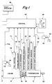
- FIGURE 1 is a schematic illustration of the components and interconnections of the automatic clutch and automatic mechanical transmission control system of the present invention.
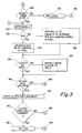
- FIGURE 2 is a time graph of the values of engine speed, throttle position and clutch engagement during a start from stop operation using the control/control method of the present invention.
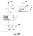
- FIGURES 3-3A are symbolic illustrations, in the form of a flow chart, illustrating the preferred manner of practicing the method of the present invention.
- FIGURE 1 schematically illustrates an automatic mechanical transmission system 10 including an automatic multi-speed compound change gear transmission 12 driven by a throttle controlled engine 14, such as a well known diesel engine, through a master clutch 16.
- An engine brake such as an exhaust brake 17 for retarding the rotational speed of engine 14 and/or an input shaft brake 18 which is effective to apply a retarding force to the input shaft upon disengagement of master clutch 16 may be provided as is known in the prior art.
- the output of automatic transmission 12 is output shaft 20 which is adopted for driving connection to an appropriate vehicle component such as the differential of a drive axle, a transfer case or the like as is well known in the prior art.
- throttle position or throttle opening monitor assembly 22 which senses the position of the operator controlled vehicle throttle or other fuel throttling device 24, a fuel control device 26 for controlling the amount of fuel (FC) to be supplied to engine 14, an engine speed sensor 28 which senses the rotational speed (N) of the engine, a clutch operator 30 which engages and disengages clutch 16 and which also supplies information as to the status of the clutch, an input brake operator 31, a transmission input shaft speed sensor 32, a transmission operator 34 which is effective to shift the transmission 12 into a selected gear ratio and to provide a signal indicative of currently engaged ratio, and a transmission output shaft speed sensor 36.
- a vehicle brake monitor 38 senses actuation of vehicle brake pedal 40.
- the above mentioned devices supply information to and/or accept commands from a central processing unit or control 42.
- the central processing unit 42 may include analogue and/or digital electronic calculation and logic circuitry, the specific configuration and structure of which forms no part of the present invention.
- the central processing unit 42 also receives information from a shift control assembly 44 by which the vehicle operator may select a reverse (R), neutral (N), or forward drive (D) mode of operation of the vehicle.
- An electrical power source (not shown) and/or source of pressurized fluid (not shown) provides electrical and/or pneumatic power to the various sensing, operating and/or processing units.
- a fault indicator or alarm 46 may display the identity of a specific fault or simply signal the existence of an unidentified fault.
- Sensors 22, 28, 32, 36, 38 and 44 may be of any known type or construction for generating analogue or digital signals proportional to the parameter monitored thereby.
- operators 17, 18, 26, 30 and 34 may be of any known electrical, pneumatic or electropneumatic type for executing operations in response to command signals from processing unit 42.
- Fuel control 26 will normally supply fuel to engine 14 in accordance with the operator's setting of throttle 24 but may supply a lesser (fuel dip) or greater (fuel boost) amount of fuel in accordance with commands from control unit 42. If the setting (FC) of the fuel control 26 differs from the setting (THL) of throttle 24, the fuel control will be ramped up or down, as appropriate, to match the throttle setting.
- US-A-4,493,228 One control system for adjusting fuel control in view of throttle setting is, by way of example only, illustrated in US-A-4,493,228.
- an input signal indicative of an engine value dependent upon engine fueling such as a signal indicative of the engine torque, may be used in place of a throttle position signal.
- control system of the present invention is particularly well suited for use with automatic clutches associated with AMT systems, the control system is also applicable to controlling the clutch and throttle start from stop operation of vehicles not having an AMT system.
- the purpose of the central processing unit 42 is to select, in accordance with a program (i.e. predetermined logic rules) and current or stored parameters, the optimal gear ratio at which the transmission should be operating and, if necessary, to command a gear change, or shift, into the selected optimal gear ratio based upon the current and/or stored information.
- a program i.e. predetermined logic rules
- central processing unit 42 central processing unit 42
- central processing unit 42 central processing unit 42
- a preferred manner of performing same may be seen in greater detail by reference to U.S.A. 4,595,986, and to published Society of Automotive Engineers SAE Paper No. 831776 published November 1983.
- fuel control 26 and clutch operator 30 are controlled as follows.
- the control, or central processing unit 42 which is preferably microprocessor based, will calculate or determine a target engine speed value (A) as a function of the sensed operator throttle setting (THL).
- THL is usually expressed as a percentage of wide open or full throttle and the target engine speed A is preferably an estimation of the engine speed (N) anticipated by the vehicle operator at a given throttle pedal setting (THL).
- Figure 2 is a time graph of a typical vehicle start from stop operation performed in accordance with the control method of the present invention.
- Line 60 illustrates the value of engine speed
- line 62 represents the value of clutch engagement with zero representing the clutch in the fully disengaged position and increasing to the fully engaged condition of the clutch
- line 64 represents the amount of fuel provided to the engine by the fuel control device 26 responding to the FC signal from the central processing unit 42.
- the driver presses the accelerator or throttle pedal 24 to a position which will depend upon whether he desires to make a gentle start or a severe start.
- the control will cause the clutch to move rapidly from the fully disengaged position to a point of incipient engagement 102 as represented by segment 104 of line 62. Having achieved incipient engagement, the clutch will continue to be moved toward engagement at a relatively low rate as indicated by segment 106 of line 64, which rate is selected to provide a smooth initial engagement of the clutch and which rate may be fixed or may vary in accordance with the value of other parameters such as the value of the operator set throttle signal THL.
- fuel will be supplied to the engine in a manner to rapidly increase the engine speed from the idle speed to the target speed A in a rapid but damped matter illustrated by portion 110 of engine speed line 60 and portion 112 of fuel line 64.
- a predetermined value 114 usually expressed as a percentage of the THL signal such as for example, 85%
- a second predetermined value 118 also expressed as a percentage of the THL signal which value 118 is preferably equal to or less than the value 114.
- the value of engine speed N will be equal to the target engine speed A
- the value of fuel supplied to the engine 124 will be equal to or greater than the predetermined value, such as 5% to 35% of the maximum amount of fuel which can be supplied to the engine (FC)
- the rate of change (dFC/dt) of the value of fuel will be positive which conditions are an indication that the engine is developing sufficient torque and that the drive line is sufficiently wound up for the clutch to be applied at a considerably increased rate as indicated by segment 126 of line 62.
- control of a start from stop operation in accordance with the control method of the present invention does not require clutch release or decreased engagement of the clutch to maintain control of the system and does utilize the relatively rapid response of the system to variations in the amount of fuel supplied to the engine as the primary controlling parameter.
- the rates of clutch engagement, especially the relatively lower rates of clutch engagement may be fixed or may vary with the values of the THL signal and/or the rate of change of the THL signal and/or the ratio of the starting gear.
- the value 124 of fuel at which the rate of clutch engagement is increased from the relatively low to the relatively rapid rates may be fixed or may vary with the values of the THL signal and/or the ratio of the starting gear.
- FC is set equal to THL until such time as a shift transient and/or a start from stop operation occurs.
- engagement of the clutch involves moving the clutch actuator toward fuller engagement of the clutch elements.
- Figures 3 and 3A are symbolic representation, in the form of a flow chart, of the method of the present invention.
- the CPU 42 will determined if a start from stop operation is occurring. If start from stop conditions are not occurring, the logic will exit from the start from stop subroutine to the remainder of the AMT logic 132. Otherwise, a value of A will be determined as indicated at operation block 134 and the current value of engine speed N will be compared to the value of A as indicated at decision block 136.
- the value of fuel supplied to the engine i.e. the value of the signal FC will be modulated to cause the engine speed N to either increase to the value A in a damping effect or to maintain the engine speed N equal to the value of A, respectively.
- clutch 16 is not in at least incipient engagement, it is rapidly moved to the position of incipient engagement.
- decision block 146 it is determined if the value of the signal FC, is greater than a value X (114), and if the engine speed is equal to the target engine speed value A and if the rate of change of the signal fc, with respect to time is positive. If all of the conditions of decision block 146 are true, the clutch is caused to rapidly engage as indicated in operational block 148 and then it is determined if the clutch is fully engaged at decision block 150. If the clutch is fully engaged, fuel control is returned to the operator as indicated at operational block 152 and the start from stop sub-routine is exited. If the clutch is not fully engaged, the logic is re-entered at point C.
- the value of the fuel control signal is compared to a value Y (114). If the value of the FC signal is less than the value of Y, the clutch is engaged at the reduced rate (see segments 106 and 120 of line 62) as shown at operational block 156 and then the routine is re-entered at point C. If the value of the fuel control signal FC is greater than the value Y, the clutch is caused to maintain its current condition of engagement (see segment 116 of line 62) until such time as the value of the fuel control signal FC is less than the value of Z (118) as indicated at decision block 165. The logic is re-entered at point D to cause the clutch to be engaged at the reduced rate. As was indicated above, the value of Y is usually greater than or equal to the value of Z.
- AMT system 10 has been described as utilizing a microprocessor based control 42 and the methods and operations carried out as software modes or algorithms, it is clear that the operations can also be carried out in electronic/fluid logic circuit comprising discrete hardware components.
- Transmission 12 may include synchronizing means such as an accelerator and/or brake mechanism as described in US-A-3,478,851.
- the transmission 12 is preferably, but not necessarily, of the twin countershaft type as seen in US-A-3,105,395.
Landscapes
- Engineering & Computer Science (AREA)
- Chemical & Material Sciences (AREA)
- Combustion & Propulsion (AREA)
- Transportation (AREA)
- Mechanical Engineering (AREA)
- Automation & Control Theory (AREA)
- Control Of Driving Devices And Active Controlling Of Vehicle (AREA)
Claims (26)
- Procédé pour commander un système de démarrage automatique d'un véhicule pour des véhicules ayant une pédale d'accélérateur (24) actionnée par le conducteur, une commande de combustible (26) pour commander la quantité de combustible apportée au moteur, une transmission (12) ayant plusieurs combinaisons de rapports de démultiplication pouvant venir en prise, de façon sélective, entre un arbre d'entrée de transmission (18) et un arbre de sortie de transmission (20) ledit arbre d'entrée de transmission étant raccordé de façon fonctionnelle audit moteur au moyen d'un embrayage à friction (16) embrayable et débrayable de façon sélective, ledit système de démarrage automatique comprenant une unité de traitement d'informations (42) ayant des moyens pour recevoir plusieurs signaux d'entrée comprenant (1) un signal d'entrée (N) indicatif de la vitesse de rotation du moteur; et (2) un signal d'entrée (THL) indicatif de la position donnée par le conducteur à la pédale d'accélérateur (24), ou du couple, ladite unité de traitement comprenant des moyens pour traiter lesdits signaux d'entrée en accord avec des règles logiques prédéterminées pour produire des signaux de sortie de commande par lesquels ledit système est mis en oeuvre en accord avec lesdites règles logiques, et des moyens (26, 30, 34) associés avec ledit système, agissant pour actionner ledit embrayage (16) et desdits moyens de commande de combustible (26) en réponse auxdits signaux de sortie de commande provenant de ladite unité de traitement ;
ladite unité de traitement (42) comprenant des moyens pour détecter une opération de démarrage d'un véhicule et, dans une opération de démarrage de véhicule, délivrant des signaux de sortie de commande auxdits moyens de commande d'embrayage (30) pour commander la vitesse de mise en contact dudit embrayage, et auxdits moyens de commande de combustible (26) pour commander la quantité de combustible apportée audit moteur, le procédé étant caractérisé par les étapes consistant à :
fixer une valeur de la vitesse du moteur à atteindre (A), moduler la quantité de combustible (FC) apportée au moteur (14) afin que la vitesse (N) du moteur, de façon amortie, devienne rapidement sensiblement égale à la vitesse du moteur à atteindre (A), au début de l'opération de démarrage du véhicule, amener ledit embrayage (16) à venir en contact avec une première vitesse de mise en contact aussi longtemps que la quantité de combustible (FC) apportée à ce moment audit moteur (14) est inférieure à une première valeur prédéterminée (Y), si la quantité de combustible apportée au moteur est égale ou supérieure à ladite première valeur prédeterminée, maintenir alors l'embrayage (16) dans sa position de contact courante jusqu'à ce que la quantité de combustible soit inférieure ou égale à une seconde valeur prédéterminées (Z), amener alors ledit embrayage vers un contact plus grand à une vitesse pas plus grande que ladite première vitesse jusqu'à ce que la vitesse du moteur atteigne la vitesse à atteindre (A), moduler alors la quantité de combustible (FC) vers ledit moteur (14) pour maintenir ladite vitesse de moteur (N) sensiblement à ladite valeur de vitesse de moteur à atteindre (A), et alors, si la différence entre la vitesse du moteur et la vitesse de l'arbre d'entrée est inférieure à une valeur de référence, amener ledit embrayage à venir en contact à une seconde vitesse de mise en contact, plus rapide. - Procédé selon la revendication 1, dans lequel ladite valeur de vitesse de moteur à atteindre (A) est une fonction de la position donnée par le conducteur à l'accélérateur (THL).
- Procédé selon la revendication 2, dans lequel, si ledit embrayage a été maintenu dans son état de contact courant en conséquence du fait que la quantité de combustible apportée au moteur est égale ou supérieure à la première valeur prédéterminée (Y), on amène ledit embrayage vers un contact plus grand à ladite première vitesse de mise en contact après que la quantité de combustible apportée à ce moment au moteur est inférieure ou égale à une seconde valeur prédeterminée (Z).
- Procédé selon la revendication 3, dans lequel ladite première valeur prédeterminée est égale ou supérieure à la seconde valeur prédéterminée.
- Procédé selon la revendication 4, dans lequel lesdites première et seconde valeurs prédeterminées sont fonction de la position donnée par le conducteur à l'accélérateur
- Procédé selon la revendication 5, dans lequel ladite première valeur prédeterminée est approximativement égale à 80% de la position donnée par le conducteur à l'accélérateur
- Procédé selon la revendication 4, dans lequel lesdites première et seconde valeurs prédeterminées sont fonction du rapport de démultiplication de la transmission dans l'opération de démarrage.
- Procédé selon la revendication 5, dans lequel lesdites première et seconde valeurs prédeterminées sont fonction du rapport de démultiplication de la transmission dans l'opération de démarrage.
- Procédé selon la revendication 4 dans lequel ladite première vitesse de mise en contact est une vitesse de mise en contact relativement lente choisie pour procurer des opérations de démarrage relativement en douceur.
- Procédé selon la revendication 2, dans lequel ladite première vitesse est une fonction de la position donnée par le conducteur à la pédale d'accélérateur.
- Procédé selon la revendication 2, dans lequel ladite première vitesse est une fonction du rapport de transmission en prise utilisé pour les opérations de démarrage.
- Procédé selon la revendication 2, dans lequel ladite unité de traitement comprend des moyens pour calculer la valeur de la vitesse de changement de la quantité de combustible apportée instantanément au moteur (14) et après que la vitesse du moteur est devenue égale et est maintenue à la valeur de la vitesse de moteur à atteindre (A), on amène ledit embrayage (16) à venir en contact (120) à ladite première vitesse de mise en contact (106) jusqu'à ce que, à la fois la quantité de combustible apportée instantanément au moteur, soit égale ou supérieure à une troisième valeur prédéterminée (X) et la vitesse de changement de la quantité de combustible apportée au moteur soit positive et, par la suite, on amène ledit embrayage à venir en contact à une seconde vitesse de mise en contact plus rapide (126).
- Procédé selon la revendication 12, dans lequel ladite seconde vitesse de mise en contact est la vitesse de mise en contact la plus rapide disponible pour la mise en contact de l'embrayage.
- Procédé selon la revendication 12, dans lequel ladite troisième valeur prédéterminée est une fonction de la position donnée par le conducteur à la pédale d'accélérateur.
- Procédé selon la revendication 12, dans lequel ladite troisième valeur prédéterminée est dans la fourchette de 5% à 35% de la valeur de la quantité maximum de combustible qui peut être apportée au moteur.
- Procédé, selon la revendication 14, dans lequel ladite troisième valeur prédéterminée est une fonction du rapport deladite transmission pendant les opérations de démarrage.
- Procédé selon la revendication 15, dans lequel ladite troisième valeur prédéterminée est une fonction du rapport deladite transmission pendant les opérations de démarrage.
- Procédé selon la revendication 3, dans lequel ladite unité de traitement comprend des moyens pour calculer la valeur de la vitesse de changement de la quantité de combustible apportée instantanément au moteur et, après que la vitesse du moteur a été rendue égale à la valeur de la vitesse de moteur à atteindre et y est maintenue, on amène ledit embrayage à être mis en contact à ladite première vitesse de mise en contact jusqu'à ce que, à la fois, la quantité de combustible apportée instantanément au moteur soit égale ou supérieure à une troisième valeur prédéterminée et la vitesse de changement de la quantité de combustible apportée au moteur soit positive et, par la suite, on amène ledit embrayage a être mis en contact à une seconde vitesse de mise en contact plus rapide.
- Procédé selon la revendication 2, dans lequel ladite unité de traitement comprend des moyens pour calculer la valeur de la différence entre la vitesse du moteur et la vitesse de l'arbre d'entrée de transmission et après que la vitesse du moteur à été rendue égale à la valeur de la vitesse de moteur à atteindre et maintenue à cette valeur, on amène ledit embrayage à être mis en contact à ladite première vitesse de mise en contact jusqu'à ce que, à la fois, la quantité de combustible apportée instantanément au moteur soit égale ou supérieure à une troisième valeur prédéterminée et la différence entre la vitesse du moteur et la vitesse de l'arbre d'entrée de transmission soit inférieure à une valeur prédéterminée et, par la suite, on amène ledit embrayage a être mis en contact à une seconde vitesse de mise en contact, plus rapide.
- Procédé selon la revendication 3, dans lequel ladite unité de traitement comprend des moyens pour calculer la valeur de la différence entre la vitesse du moteur et la vitesse de l'arbre d'entrée de transmission et, après que la vitesse du moteur à été rendue égale à la valeur de la vitesse de moteur à atteindre et maintenue à cette valeur, on amène, ledit embrayage à être mis en contact à ladite première vitesse de mise en contact jusqu'à ce que, à la fois, la quantité de combustible apportée instantanément au moteur soit égale ou supérieure à une troisième valeur prédeterminée et la différence entre la vitesse du moteur et la vitesse de l'arbre d'entrée de transmission soit inférieure à une valeur prédéterminée et, par la suite, on amène ledit embrayage à venir en contact à une seconde vitesse de mise en contact, plus rapide.
- Procédé selon l'une quelconque des revendications précédentes, dans lequel ladite première vitesse de mise en contact (106, 120) est une vitesse de mise en contact choisie pour permettre les opérations de démarrage.
- Procédé selon la revendication 21, dans lequel ladite première vitesse de mise en contact est aussi une fonction de la position donnée par le conducteur à la pédale d'embrayage.
- Procédé selon les revendications 21 ou 22, dans lequel ladite ladite seconde vitesse de mise en contact (126) est une vitesse de mise en contact plus rapide pour mettre en contact ledit embrayage que l'est ladite première vitesse (106, 120).
- Procédé selon l'une quelconque des revendications précédentes, dans lequel ladite valeur de référence est une fonction de la position donné par le conducteur (THL) à ladite pédale d'accélérateur (24).
- Procédé selon l'une quelconque des revendications précédentes, dans lequel ladite valeur de référence est une fonction de la quantité de combustible qui est apportée au moteur.
- Procédé selon l'une quelconque des revendications précédentes, dans lequel ladite valeur de référence est une fonction du rapport deladite transmission pendant les opérations de démarrage.
Applications Claiming Priority (2)
| Application Number | Priority Date | Filing Date | Title |
|---|---|---|---|
| US154562 | 1988-02-10 | ||
| US07/154,562 US4873637A (en) | 1988-02-10 | 1988-02-10 | Control for vehicle start from stop operation |
Publications (3)
| Publication Number | Publication Date |
|---|---|
| EP0328362A2 EP0328362A2 (fr) | 1989-08-16 |
| EP0328362A3 EP0328362A3 (en) | 1989-12-06 |
| EP0328362B1 true EP0328362B1 (fr) | 1993-12-01 |
Family
ID=22551820
Family Applications (1)
| Application Number | Title | Priority Date | Filing Date |
|---|---|---|---|
| EP89301196A Expired - Lifetime EP0328362B1 (fr) | 1988-02-10 | 1989-02-08 | Commande pour la procédure de démarrage d'un véhicule |
Country Status (3)
| Country | Link |
|---|---|
| US (1) | US4873637A (fr) |
| EP (1) | EP0328362B1 (fr) |
| DE (1) | DE68910995T2 (fr) |
Families Citing this family (50)
| Publication number | Priority date | Publication date | Assignee | Title |
|---|---|---|---|---|
| US4998444A (en) * | 1987-07-16 | 1991-03-12 | Automotive Products (Usa) Inc. | Control system for electric shift apparatus |
| US5014038A (en) * | 1987-09-14 | 1991-05-07 | Automotive Products (Usa) Inc. | Motor vehicle control system |
| JPH01249534A (ja) * | 1988-03-31 | 1989-10-04 | Nissan Motor Co Ltd | 車両の制御装置 |
| JP2888298B2 (ja) * | 1988-12-09 | 1999-05-10 | 日産自動車株式会社 | 自動変速機のセレクトショック防止装置 |
| GB2228980A (en) * | 1989-03-06 | 1990-09-12 | Zahnradfabrik Friedrichshafen | Gearshift control with automatic control of clutch |
| US5042133A (en) * | 1989-03-15 | 1991-08-27 | Automotive Products (Usa) Inc. | Testing method for electric shift control apparatus |
| US5035158A (en) * | 1989-09-25 | 1991-07-30 | Automotive Products (Usa) Inc. | Electric shift and transfer case apparatus with control system therefore |
| US4989471A (en) * | 1989-12-01 | 1991-02-05 | Ford New Holland, Inc. | Method of calibrating clutches in transmissions |
| US5081588A (en) * | 1990-03-26 | 1992-01-14 | Eaton Corporation | Start from stop control method |
| US5305213A (en) * | 1991-05-09 | 1994-04-19 | Eaton Corporation | Driveline torque limit control strategy-using SAE J1922 type engine control |
| GB9218274D0 (en) * | 1992-08-27 | 1992-10-14 | Eaton Corp | Start ratio selection control system and method |
| GB9218273D0 (en) * | 1992-08-27 | 1992-10-14 | Eaton Corp | Scrolling gear ratio selection control system and method |
| GB9218254D0 (en) * | 1992-08-27 | 1992-10-14 | Eaton Corp | Start ratio engagement control system and method |
| US5416698A (en) * | 1993-07-09 | 1995-05-16 | Eaton Corporation | Input shaft overspeed warning system |
| GB9421350D0 (en) | 1994-10-24 | 1994-12-07 | Eaton Corp | Automated clutch control and calibration |
| US5529548A (en) * | 1995-01-09 | 1996-06-25 | Eaton Corporation | Vehicle launch engine fuel control |
| JPH08200493A (ja) * | 1995-01-23 | 1996-08-06 | Nippon Soken Inc | 自動変速装置 |
| JP3787978B2 (ja) * | 1997-09-12 | 2006-06-21 | いすゞ自動車株式会社 | クラッチ断接装置 |
| IT1308785B1 (it) * | 1999-07-02 | 2002-01-10 | Magneti Marelli Spa | Gruppo di trasmissione per un veicolo. |
| US6217479B1 (en) * | 1999-07-15 | 2001-04-17 | Ford Global Technologies, Inc. | Converterless multiple-ratio automatic transmission |
| JP3675281B2 (ja) * | 2000-02-15 | 2005-07-27 | 日産自動車株式会社 | 車両のエンジン自動停止再始動装置 |
| JP4078789B2 (ja) * | 2000-04-21 | 2008-04-23 | アイシン・エィ・ダブリュ株式会社 | 自動変速機におけるロックアップ制御装置 |
| US7108117B2 (en) * | 2000-12-13 | 2006-09-19 | Eaton Corporation | Centrifugal clutch |
| US6561948B2 (en) * | 2000-12-13 | 2003-05-13 | Eaton Corporation | Control for transmission system utilizing centrifugal clutch |
| EP1513700B1 (fr) * | 2002-06-17 | 2011-05-04 | Continental Automotive GmbH | Procede de regulation d'un couple |
| US20050109141A1 (en) * | 2003-11-25 | 2005-05-26 | Devore James H. | Automated mechanical transmission system |
| JP2005180623A (ja) * | 2003-12-22 | 2005-07-07 | Hitachi Ltd | 自動変速機、及びその制御装置、並びに制御システム |
| US7912613B2 (en) | 2004-07-01 | 2011-03-22 | Yamaha Hatsudoki Kabushiki Kaisha | Riding type vehicle |
| CN100491778C (zh) | 2004-07-01 | 2009-05-27 | 雅马哈发动机株式会社 | 用于跨骑式车辆的换档控制设备以及跨骑式车辆 |
| US8403093B2 (en) | 2004-07-26 | 2013-03-26 | Yamaha Hatsudoki Kabushiki Kaisha | Speed change controller for saddle-ride type vehicles |
| JP4608298B2 (ja) | 2004-12-10 | 2011-01-12 | ヤマハ発動機株式会社 | 変速制御装置、変速制御方法及び鞍乗型車両 |
| JP4873542B2 (ja) | 2006-04-18 | 2012-02-08 | ヤマハ発動機株式会社 | 自動変速制御装置および車両 |
| JP4863755B2 (ja) | 2006-04-18 | 2012-01-25 | ヤマハ発動機株式会社 | クラッチ用アクチュエータ、エンジンユニットおよび鞍乗型車両 |
| JP5089056B2 (ja) | 2006-02-24 | 2012-12-05 | ヤマハ発動機株式会社 | クラッチ異常検出装置、自動クラッチ装置および鞍乗型車両 |
| JP5164337B2 (ja) | 2006-04-18 | 2013-03-21 | ヤマハ発動機株式会社 | 自動変速制御装置および鞍乗型車両 |
| JP4789688B2 (ja) | 2006-04-18 | 2011-10-12 | ヤマハ発動機株式会社 | クラッチ用アクチュエータ、エンジンユニットおよび鞍乗型車両 |
| JP5121159B2 (ja) | 2006-04-18 | 2013-01-16 | ヤマハ発動機株式会社 | 自動変速制御装置および車両 |
| JP4873543B2 (ja) | 2006-04-18 | 2012-02-08 | ヤマハ発動機株式会社 | 自動変速制御装置および車両 |
| DE602006018799D1 (de) * | 2006-02-24 | 2011-01-20 | Yamaha Motor Co Ltd | Gangwechselverfahren für eine automatisierte Schaltgetriebeeinheit und automatisiertes Getriebe für ein Fahrzeug |
| JP4972334B2 (ja) | 2006-04-18 | 2012-07-11 | ヤマハ発動機株式会社 | クラッチ用アクチュエータ、エンジンユニットおよび鞍乗型車両 |
| JP4931464B2 (ja) | 2006-04-18 | 2012-05-16 | ヤマハ発動機株式会社 | クラッチ制御装置および車両 |
| TWI293603B (en) | 2006-04-18 | 2008-02-21 | Yamaha Motor Co Ltd | Shift actuator, vehicle, and method of integrating vehicle |
| JP4654173B2 (ja) * | 2006-11-16 | 2011-03-16 | 日立オートモティブシステムズ株式会社 | 車両の制御装置 |
| JP4625824B2 (ja) * | 2007-04-25 | 2011-02-02 | ボッシュ株式会社 | 内燃機関出力制御方法及びその装置 |
| US8738256B2 (en) * | 2008-07-01 | 2014-05-27 | Eaton Corporation | Automatic calibration of the torque transfer touch point in an electrically actuated clutch in a hybrid vehicle |
| US8116956B2 (en) * | 2008-07-01 | 2012-02-14 | Eaton Corporation | Fault tolerant clutch actuator |
| DE102011010616A1 (de) * | 2010-07-23 | 2012-01-26 | Magna Powertrain Ag & Co. Kg | Verfahren zum Betrieb eines Antriebsstrangs eines Kraftfahrzeugs und entsprechender Antriebsstrang |
| CN103982650B (zh) * | 2014-06-03 | 2016-06-08 | 盛瑞传动股份有限公司 | 液力自动变速器离合器的半接合点判定方法和系统 |
| JP2018027743A (ja) | 2016-08-17 | 2018-02-22 | ヤマハ発動機株式会社 | 車両及びその制御方法 |
| CN109987094B (zh) * | 2017-12-29 | 2020-10-09 | 广州汽车集团股份有限公司 | 车辆起步的发动机控制方法、装置与计算机可读存储介质 |
Family Cites Families (10)
| Publication number | Priority date | Publication date | Assignee | Title |
|---|---|---|---|---|
| AU1725283A (en) * | 1982-08-11 | 1984-02-16 | Automotive Products Plc | Clutch control system |
| JPH0729569B2 (ja) * | 1983-06-29 | 1995-04-05 | いすゞ自動車株式会社 | 自動クラッチ制御装置 |
| JPS60139534A (ja) * | 1983-12-27 | 1985-07-24 | Fuji Heavy Ind Ltd | 車両用電磁式クラツチのクラツチトルク制御装置 |
| JPS60174332A (ja) * | 1984-02-16 | 1985-09-07 | Diesel Kiki Co Ltd | 車輛用自動変速装置 |
| JPS61196831A (ja) * | 1985-02-26 | 1986-09-01 | Diesel Kiki Co Ltd | 内燃機関車輛用自動発進制御装置 |
| DE3611256C2 (de) * | 1985-04-06 | 1994-08-25 | Nissan Motor | Vorrichtung zum Regeln der Anfahrkupplung eines automatischen Getriebes |
| JPS62103232A (ja) * | 1985-10-30 | 1987-05-13 | Diesel Kiki Co Ltd | クラツチ制御装置 |
| JPS62103236A (ja) * | 1985-10-30 | 1987-05-13 | Diesel Kiki Co Ltd | クラッチ制御装置 |
| US4638898A (en) * | 1985-12-19 | 1987-01-27 | Eaton Corporation | Clutch control system and clutch assembly using same |
| US4714144A (en) * | 1986-04-18 | 1987-12-22 | Eaton Corporation | Method for controlling AMT system start from stop operation |
-
1988
- 1988-02-10 US US07/154,562 patent/US4873637A/en not_active Expired - Lifetime
-
1989
- 1989-02-08 EP EP89301196A patent/EP0328362B1/fr not_active Expired - Lifetime
- 1989-02-08 DE DE68910995T patent/DE68910995T2/de not_active Expired - Lifetime
Also Published As
| Publication number | Publication date |
|---|---|
| EP0328362A2 (fr) | 1989-08-16 |
| US4873637A (en) | 1989-10-10 |
| DE68910995D1 (de) | 1994-01-13 |
| DE68910995T2 (de) | 1994-06-30 |
| EP0328362A3 (en) | 1989-12-06 |
Similar Documents
| Publication | Publication Date | Title |
|---|---|---|
| EP0328362B1 (fr) | Commande pour la procédure de démarrage d'un véhicule | |
| EP0328299B1 (fr) | Commande du démarrage dans un système de transmission mécanique automatique, à partir de l'arrêt | |
| US4714144A (en) | Method for controlling AMT system start from stop operation | |
| US4933850A (en) | Control and method for controlling AMT system including manually operated engine compression brake | |
| US5378211A (en) | Clutch mode control logic | |
| US5316116A (en) | Engine control method for use with automatic clutch control | |
| US4916979A (en) | On-grade shift logic with provision for skip downshifts | |
| US4947331A (en) | Upshift logic | |
| US4852006A (en) | Amt off-highway downshift logic | |
| US5875410A (en) | Dynamic best gear selection for automated transmission system | |
| US4711141A (en) | Method for controlling AMT system including after transmission gear change clutch and fuel control | |
| US6066071A (en) | Automated transmission downshift control | |
| JPH1071875A (ja) | 自動車並びに該自動車の適用のための方法 | |
| US6461273B1 (en) | Automated transmission upshift brake control | |
| CA1304473C (fr) | Methode de commande de transmission automatique comprenant la commande de l'alimentation en carburant en fonction de la vitesse selectionnee au levier | |
| EP1070880B1 (fr) | Commande adaptative de passages descendant des rapports d'une boíte de vitesses automatisée | |
| EP1606529B1 (fr) | Systeme et procede de commande d'enclenchement d'un embrayage |
Legal Events
| Date | Code | Title | Description |
|---|---|---|---|
| PUAI | Public reference made under article 153(3) epc to a published international application that has entered the european phase |
Free format text: ORIGINAL CODE: 0009012 |
|
| AK | Designated contracting states |
Kind code of ref document: A2 Designated state(s): DE FR GB IT SE |
|
| PUAL | Search report despatched |
Free format text: ORIGINAL CODE: 0009013 |
|
| AK | Designated contracting states |
Kind code of ref document: A3 Designated state(s): DE FR GB IT SE |
|
| 17P | Request for examination filed |
Effective date: 19900331 |
|
| 17Q | First examination report despatched |
Effective date: 19920602 |
|
| GRAA | (expected) grant |
Free format text: ORIGINAL CODE: 0009210 |
|
| ITF | It: translation for a ep patent filed | ||
| AK | Designated contracting states |
Kind code of ref document: B1 Designated state(s): DE FR GB IT SE |
|
| REF | Corresponds to: |
Ref document number: 68910995 Country of ref document: DE Date of ref document: 19940113 |
|
| ET | Fr: translation filed | ||
| PLBE | No opposition filed within time limit |
Free format text: ORIGINAL CODE: 0009261 |
|
| STAA | Information on the status of an ep patent application or granted ep patent |
Free format text: STATUS: NO OPPOSITION FILED WITHIN TIME LIMIT |
|
| 26N | No opposition filed | ||
| EAL | Se: european patent in force in sweden |
Ref document number: 89301196.5 |
|
| REG | Reference to a national code |
Ref country code: GB Ref legal event code: IF02 |
|
| PGFP | Annual fee paid to national office [announced via postgrant information from national office to epo] |
Ref country code: FR Payment date: 20060202 Year of fee payment: 18 |
|
| PGFP | Annual fee paid to national office [announced via postgrant information from national office to epo] |
Ref country code: IT Payment date: 20060228 Year of fee payment: 18 |
|
| REG | Reference to a national code |
Ref country code: FR Ref legal event code: ST Effective date: 20071030 |
|
| PG25 | Lapsed in a contracting state [announced via postgrant information from national office to epo] |
Ref country code: FR Free format text: LAPSE BECAUSE OF NON-PAYMENT OF DUE FEES Effective date: 20070228 |
|
| PGFP | Annual fee paid to national office [announced via postgrant information from national office to epo] |
Ref country code: DE Payment date: 20080229 Year of fee payment: 20 Ref country code: GB Payment date: 20080108 Year of fee payment: 20 Ref country code: SE Payment date: 20080208 Year of fee payment: 20 |
|
| REG | Reference to a national code |
Ref country code: GB Ref legal event code: PE20 Expiry date: 20090207 |
|
| EUG | Se: european patent has lapsed | ||
| PG25 | Lapsed in a contracting state [announced via postgrant information from national office to epo] |
Ref country code: GB Free format text: LAPSE BECAUSE OF EXPIRATION OF PROTECTION Effective date: 20090207 |
|
| PG25 | Lapsed in a contracting state [announced via postgrant information from national office to epo] |
Ref country code: IT Free format text: LAPSE BECAUSE OF NON-PAYMENT OF DUE FEES Effective date: 20070208 |