EP0328095B1 - Procédé de fabrication d'une tête de brûleur à gaz à partir d'une pièce en tôle découpée - Google Patents
Procédé de fabrication d'une tête de brûleur à gaz à partir d'une pièce en tôle découpée Download PDFInfo
- Publication number
- EP0328095B1 EP0328095B1 EP19890102223 EP89102223A EP0328095B1 EP 0328095 B1 EP0328095 B1 EP 0328095B1 EP 19890102223 EP19890102223 EP 19890102223 EP 89102223 A EP89102223 A EP 89102223A EP 0328095 B1 EP0328095 B1 EP 0328095B1
- Authority
- EP
- European Patent Office
- Prior art keywords
- burner
- sheet metal
- longitudinal portions
- portions
- metal blank
- Prior art date
- Legal status (The legal status is an assumption and is not a legal conclusion. Google has not performed a legal analysis and makes no representation as to the accuracy of the status listed.)
- Expired - Lifetime
Links
Images


Classifications
-
- F—MECHANICAL ENGINEERING; LIGHTING; HEATING; WEAPONS; BLASTING
- F23—COMBUSTION APPARATUS; COMBUSTION PROCESSES
- F23D—BURNERS
- F23D14/00—Burners for combustion of a gas, e.g. of a gas stored under pressure as a liquid
- F23D14/46—Details
-
- B—PERFORMING OPERATIONS; TRANSPORTING
- B21—MECHANICAL METAL-WORKING WITHOUT ESSENTIALLY REMOVING MATERIAL; PUNCHING METAL
- B21D—WORKING OR PROCESSING OF SHEET METAL OR METAL TUBES, RODS OR PROFILES WITHOUT ESSENTIALLY REMOVING MATERIAL; PUNCHING METAL
- B21D53/00—Making other particular articles
Definitions
- the invention relates first of all to a method for producing a burner plate that forms the burner plate, delimits an elongated burner chamber with longitudinal side walls and, in a central trough, a bearing for an upper part of a gas burner that has a longitudinal cooling tube from a sheet metal blank.
- the object of the invention is to provide a method which makes it possible to produce this upper part of the burner with all of its essential components for the design of the burner chamber in a few, easily executable work steps from a single sheet metal blank.
- a burner upper part can be produced in a comparatively simple and cost-effective manner, which is characterized by a high and easily achievable gas tightness of the burner chamber and by a technically advantageous design of the flame area.
- outer edge zones of the two inner longitudinal regions, together with adjacent inner edge zones of the two outer longitudinal regions, can point inward toward the center of the width of the burner Be inclined.
- the front edges of the two inner longitudinal areas can also be deformed into flanges for this purpose.
- This process step can be coupled very advantageously with the pressing of the two longitudinal side walls of the upper burner part against one another at their desired distance, that is to say with the last process step.
- the invention also extends to an upper part of a gas burner produced by the method according to the invention.
- Such an upper part formed from a single sheet metal blank is fitted onto the upper edges of the walls of a gas-air mixture distributor, the two outer longitudinal regions forming the side walls of the upper part and together delimiting a burner chamber, which is at the top by one of the two inner Longitudinal areas formed, with a longitudinal trough for a cooling tube and with this trough extending obliquely upwards on both sides and through which mixture outlet openings are profiled side plates.
- the method according to the invention enables a gas-tight connection of the end wall parts formed by the extensions of the sheet metal blank arranged on both ends with the front edges of the inner longitudinal regions of the blank forming the burner plate.
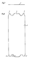
- FIGS. 7 and 8 first show the still flat, undeformed sheet metal blank 1, on the end faces of which two lateral extensions 2 and a central projection 3 each protrude.
- the extensions 2 later serve to form end walls delimiting the end faces of the burner chamber, the projections 3 and the knobs 4 shown in FIG. 1 serve to hold a cooling tube 5 in a longitudinal trough 7 (FIG. 6).
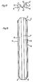
- the extensions 2 are bent approximately perpendicular to the plane of the sheet metal blank 1, as shown in FIGS. 1, 9 and 10, and at the same time the two longitudinal edges 6 of the sheet metal blank 1 are bent into a position inclined to its plane.
- the depression 7 for the cooling tube 5 is formed by pulling, in the same process step also the inner longitudinal regions 8, which later serve as the burner plate and are to be provided with the mixture outlet openings, and which extend on both sides of the depression 7 Oblique position with respect to the outer longitudinal regions 9 are deformed.
- the third method step involves pre-bending those edge zones 10 of the inner longitudinal regions 8 which directly adjoin the outer longitudinal regions 9. These edge zones 10 are pre-bent with respect to the edge zones 11 of the two outer longitudinal regions 9 into a position which is initially perpendicular to these longitudinal regions 9.
- the fourth method step comprises raising the two outer longitudinal regions 9, which thereby come to lie in a common horizontal plane, the obtuse angle between the inner longitudinal regions 8 and their edge zones 10 being reduced.
- the two outer longitudinal regions 9 are bent into a position parallel to one another, but do not yet have their desired distance, but an excessively large distance. Simultaneously with this bending of the outer longitudinal regions 9, the edge zones 11 of these longitudinal regions 9 are folded, to be precise in a width which corresponds to the width of the edge zones 10 of the two inner longitudinal regions 8.
- the two outer longitudinal regions 9, as the longitudinal side walls of the finished burner chamber 14 are placed on the upper edges of the longitudinal side walls 13 of a mixture distribution chamber 12 and on their desired distance, which corresponds to the width of the burner chamber 14, pressed against each other, the extensions 2 each forming an end wall of the burner chamber 14 and sealing this burner chamber 14 gas-tight.
- the end wall of the trough 7 for the cooling tube 5 receives a collar 15 formed from the projection 3 of the sheet metal blank 1, which serves as a seal, and the two inner longitudinal regions 8 with the mixture outlet openings each receive a joint which also serves to seal the end walls of the burner chamber 14 the end extensions 2 of the sheet metal blank 1 sealing flange 16.
- edge zones 10 and 11 of the inner and outer longitudinal regions 8 and 9 are jointly bent inward and form a solid, mutually adjacent shield for the flame region of the burner and a secondary air duct.
Landscapes
- Engineering & Computer Science (AREA)
- Mechanical Engineering (AREA)
- Chemical & Material Sciences (AREA)
- Combustion & Propulsion (AREA)
- General Engineering & Computer Science (AREA)
- Gas Burners (AREA)
- Shaping Metal By Deep-Drawing, Or The Like (AREA)
Claims (9)
- Procédé pour la fabrication d'une tête d'un brûleur à gaz à partir d'un flan, caractérisé par le fait que d'abord, aux bouts du flan (1) qui a une longueur correspondant à celle du brûleur, des languettes (2) sont repliées, s'étendant dans le sens de la longueur du flan (1) et destinées à former les parois frontales du corps du brûleur (14) et disposées de part et d'autre du milieu de ce flan, puis, au milieu du flan (1), un creux (7) est exécuté par emboutissage, destiné à recevoir le tube de refroidissement (5), puis les deux bandes intérieures (8) de part et d'autre dudit creux (7) sont repliées pour former la platine du brûleur et les mettre dans une position inclinée par rapport aux bandes extérieures (9) servant à la réalisation des parois latérales du corps du brûleur (14), et finalement ces deux bandes extérieures (9) sont déformées pour les mettre dans une position parallèle l'une vis-à-vis de l'autre, à une distance correspondant à la largeur du corps du brûleur (14) (Fig. 1 à 6 et 7 à 20).
- Procédé suivant la revendication 1, caractérisé par le fait que des zones marginales extérieures (10) des deux bandes intérieures (8) sont pliées ensemble avec des zones marginales intérieures (11) des deux bandes extérieures (9) pour former des rebords délimitant la zone de combustion du brûleur dans une position inclinée dirigée vers le milieu du brûleur (Fig. 3 à 6).
- Procédé suivant la revendication 2, caractérisé par le fait que les deux zones marginales extérieures (10) des deux bandes intérieures (8) sont prépliées en même temps que les deux bandes extérieures (9) sont pliées, et puis dressées ensemble avec lesdites bandes extérieures (9) (Fig. 3, 4).
- Procédé suivant l'une des revendications 2 ou 3, caractérisé par le fait que les zones marginales intérieures (11) des deux bandes extérieures (9) sont pliées et mises dans une position inclinée au moment de la mise en parallèle desdites bandes (9), et poussées avec les zones marginales extérieures (10) des bandes intérieures (8) vers l'intérieur pour les mettre dans cette position inclinée (Fig. 5, 6).
- Procédé suivant l'une des revendications 1 à 4, caractérisé par le fait que des parties du bord en saillie (3) aux deux bouts et au milieu du flan (1) sont déformées pour réaliser ainsi un rebord (15) du creux (7) servant au logement du tube de refroidissement (5) (Fig. 19, 20).
- Procédé suivant l'une des revendications 1 à 5, caractérisé par le fait que les bords en bout des deux bandes intérieures (8) sont exécutés en collerettes (16) (Fig. 19, 20).
- Brûleur à gaz avec une tête réalisée par le procédé suivant l'une des revendications 1 à 6, caractérisé par le fait que cette tête formée à partir d'un flan (1) unique, est placée par ajustement fin sur les bords supérieurs des parois (13) d'un distributeur de mélange gaz-air (12), les deux bandes extérieures (9) formant les parois latérales de ladite tête, délimitant ensemble un corps de brûleur (14) qui est fermé en haut par une platine formée par les bandes intérieures (8) et un creux (7) longitudinal pour un tube de refroidissement (5), et des bandes inclinées de part et d'autre dudit creux (7) et munies d'orifices de sortie pour le mélange (Fig. 6).
- Brûleur à gaz suivant la revendication 7, caractérisé par un assemblage étanche des parois frontales formées par les languettes (2) aux bouts du flan (1) avec les bandes intérieures (8) formant la platine du brûleur (Fig. 19).
- Brûleur à gaz suivant la revendication 7 ou 8, caractérisé par le fait que les deux bords (6) de la tête du brûleur sont recourbés vers l'extérieur pour faciliter le montage sur les parois (13) du distributeur de mélange (12).
Applications Claiming Priority (2)
| Application Number | Priority Date | Filing Date | Title |
|---|---|---|---|
| AT247/88 | 1988-02-08 | ||
| AT0024788A AT389248B (de) | 1988-02-08 | 1988-02-08 | Verfahren zur herstellung eines oberteils eines gasbrenners und nach dem verfahren hergestellter gasbrenneroberteil |
Publications (3)
| Publication Number | Publication Date |
|---|---|
| EP0328095A2 EP0328095A2 (fr) | 1989-08-16 |
| EP0328095A3 EP0328095A3 (en) | 1990-05-16 |
| EP0328095B1 true EP0328095B1 (fr) | 1993-06-16 |
Family
ID=3485460
Family Applications (1)
| Application Number | Title | Priority Date | Filing Date |
|---|---|---|---|
| EP19890102223 Expired - Lifetime EP0328095B1 (fr) | 1988-02-08 | 1989-02-08 | Procédé de fabrication d'une tête de brûleur à gaz à partir d'une pièce en tôle découpée |
Country Status (3)
| Country | Link |
|---|---|
| EP (1) | EP0328095B1 (fr) |
| AT (2) | AT389248B (fr) |
| DE (2) | DE58904669D1 (fr) |
Families Citing this family (3)
| Publication number | Priority date | Publication date | Assignee | Title |
|---|---|---|---|---|
| ES2044740B1 (es) * | 1991-05-13 | 1996-11-16 | Fagor S Coop | Mejoras en quemadores atmosfericos para calentadores de gas y/o similares. |
| AT397566B (de) * | 1992-05-11 | 1994-05-25 | Vaillant Gmbh | Mischkammeranordnung für brenner und verfahren zur herstellung derselben |
| CN111964060B (zh) * | 2020-08-06 | 2024-10-01 | 广东合创达电器科技有限公司 | 一种外环火盖及其燃气炉装置 |
Family Cites Families (6)
| Publication number | Priority date | Publication date | Assignee | Title |
|---|---|---|---|---|
| US3312267A (en) * | 1964-01-13 | 1967-04-04 | Johnson Corp | Gas burner |
| US3499308A (en) * | 1967-03-22 | 1970-03-10 | Tepfer & Sons Inc S | Molding metal |
| FI49248C (fi) * | 1972-07-03 | 1975-05-12 | Valmet Oy | Peltikanavien saumausmenetelmä. |
| DE2434841C2 (de) * | 1974-07-19 | 1976-09-09 | Joh. Vaillant Kg, 5630 Remscheid | Verfahren zur herstellung einer brennerkammer |
| DE8604050U1 (de) * | 1986-02-12 | 1986-06-26 | Joh. Vaillant Gmbh U. Co, 5630 Remscheid | Vormischgasbrenner |
| AT393015B (de) * | 1987-09-21 | 1991-07-25 | Vaillant Gmbh | Gasbrenner |
-
1988
- 1988-02-08 AT AT0024788A patent/AT389248B/de not_active IP Right Cessation
-
1989
- 1989-02-08 DE DE8989102223T patent/DE58904669D1/de not_active Expired - Fee Related
- 1989-02-08 EP EP19890102223 patent/EP0328095B1/fr not_active Expired - Lifetime
- 1989-02-08 AT AT89102223T patent/ATE90786T1/de not_active IP Right Cessation
- 1989-02-08 DE DE3903689A patent/DE3903689A1/de not_active Withdrawn
Also Published As
| Publication number | Publication date |
|---|---|
| DE58904669D1 (de) | 1993-07-22 |
| DE3903689A1 (de) | 1989-08-17 |
| ATE90786T1 (de) | 1993-07-15 |
| ATA24788A (de) | 1989-04-15 |
| AT389248B (de) | 1989-11-10 |
| EP0328095A3 (en) | 1990-05-16 |
| EP0328095A2 (fr) | 1989-08-16 |
Similar Documents
| Publication | Publication Date | Title |
|---|---|---|
| DE3428179A1 (de) | Blechkanal-system mit mitteln zum verbinden der enden der einzelnen kanalsektionen sowie eckverbinder zum ausfuehren der verbindungen | |
| DE1967052A1 (de) | Waermeaustauscher nach art eines roehrenkuehlers | |
| EP0328095B1 (fr) | Procédé de fabrication d'une tête de brûleur à gaz à partir d'une pièce en tôle découpée | |
| DE2612117C2 (fr) | ||
| EP0057879B1 (fr) | Chemin de câbles comme porteur de câbles électriques | |
| EP1376043A2 (fr) | Echangeur de chaleur avec diffuseur | |
| DE10153877A1 (de) | Wärmeübertrager | |
| EP0305920B1 (fr) | Récipient, plus particulièrement fût | |
| DE2829973B2 (de) | Lochmaske für eine Lochmasken-Kathodenstrahlröhre | |
| DE2402876C3 (de) | Deckenelement | |
| EP0689025A1 (fr) | Procédé de soudage de profilés d'etanchéité de type peigne, à des échangeurs de chaleur à plaques | |
| DE2233471A1 (de) | Deckenblech fuer eine rechteckige leuchte | |
| AT395759B (de) | Gasbrenner | |
| DE2159386B2 (de) | Verfahren zum herstellen einer pyramidenstumpffoermigen magnetischen abschirmung und zu deren einbau in eine kathodenstrahlroehre | |
| DE4214514A1 (de) | Flansch, insbesondere zur befestigung von abgasrohren | |
| EP0360097A1 (fr) | Panneau rayonnant suspendu | |
| DE4338959C2 (de) | Wasser/Luft-Wärmetauscher für Kraftfahrzeuge und Herstellungsverfahren für diesen | |
| DE2121897C3 (de) | Reihengasbrenner | |
| DE10214241B4 (de) | Kanalförmiges Gehäuse für eine Absperrvorrichtung in Lüftungsleitungen, Absperrvorrichtung mit demselben und Verfahren zur Herstellung desselben | |
| EP1472429B1 (fr) | Procede de production d'un vantail de porte en tole metallique et vantail de porte pouvant etre produit par ce procede | |
| AT397566B (de) | Mischkammeranordnung für brenner und verfahren zur herstellung derselben | |
| DE2324649C2 (de) | Wärmetauscher für motorunabhängige Heizungen in Kraftfahrzeugen | |
| DE960107C (de) | Abschirmeinrichtung unter Verwendung von Wellblechtafeln | |
| DE69013545T2 (de) | Elektronenkanone für eine Kathodenstrahlröhre. | |
| DE10019268A1 (de) | Kühler für Kraftfahrzeuge |
Legal Events
| Date | Code | Title | Description |
|---|---|---|---|
| PUAI | Public reference made under article 153(3) epc to a published international application that has entered the european phase |
Free format text: ORIGINAL CODE: 0009012 |
|
| AK | Designated contracting states |
Kind code of ref document: A2 Designated state(s): AT BE CH DE ES FR GB GR IT LI LU NL SE |
|
| PUAL | Search report despatched |
Free format text: ORIGINAL CODE: 0009013 |
|
| AK | Designated contracting states |
Kind code of ref document: A3 Designated state(s): AT BE CH DE ES FR GB GR IT LI LU NL SE |
|
| 17P | Request for examination filed |
Effective date: 19901108 |
|
| 17Q | First examination report despatched |
Effective date: 19910902 |
|
| RAP1 | Party data changed (applicant data changed or rights of an application transferred) |
Owner name: VAILLANT GMBH Owner name: VAILLANT B.V. Owner name: VAILLANT LTD. Owner name: VAILLANT GES.M.B.H Owner name: VAILLANT S.A.R.L Owner name: N.V. VAILLANT S.A. Owner name: JOH. VAILLANT GMBH U. CO. |
|
| GRAA | (expected) grant |
Free format text: ORIGINAL CODE: 0009210 |
|
| AK | Designated contracting states |
Kind code of ref document: B1 Designated state(s): AT BE CH DE ES FR GB GR IT LI LU NL SE |
|
| PG25 | Lapsed in a contracting state [announced via postgrant information from national office to epo] |
Ref country code: SE Effective date: 19930616 Ref country code: GR Free format text: LAPSE BECAUSE OF FAILURE TO SUBMIT A TRANSLATION OF THE DESCRIPTION OR TO PAY THE FEE WITHIN THE PRESCRIBED TIME-LIMIT Effective date: 19930616 Ref country code: ES Free format text: THE PATENT HAS BEEN ANNULLED BY A DECISION OF A NATIONAL AUTHORITY Effective date: 19930616 Ref country code: BE Effective date: 19930616 |
|
| REF | Corresponds to: |
Ref document number: 90786 Country of ref document: AT Date of ref document: 19930715 Kind code of ref document: T |
|
| ITF | It: translation for a ep patent filed | ||
| REF | Corresponds to: |
Ref document number: 58904669 Country of ref document: DE Date of ref document: 19930722 |
|
| GBT | Gb: translation of ep patent filed (gb section 77(6)(a)/1977) |
Effective date: 19930628 |
|
| RAP4 | Party data changed (patent owner data changed or rights of a patent transferred) |
Owner name: VAILLANT GMBH Owner name: VAILLANT B.V. Owner name: VAILLANT LTD. Owner name: VAILLANT GES.M.B.H Owner name: VAILLANT S.A.R.L Owner name: N.V. VAILLANT S.A. Owner name: JOH. VAILLANT GMBH U. CO. |
|
| ET | Fr: translation filed | ||
| PGFP | Annual fee paid to national office [announced via postgrant information from national office to epo] |
Ref country code: FR Payment date: 19931201 Year of fee payment: 6 |
|
| PGFP | Annual fee paid to national office [announced via postgrant information from national office to epo] |
Ref country code: GB Payment date: 19931206 Year of fee payment: 6 |
|
| PGFP | Annual fee paid to national office [announced via postgrant information from national office to epo] |
Ref country code: DE Payment date: 19931228 Year of fee payment: 6 |
|
| PGFP | Annual fee paid to national office [announced via postgrant information from national office to epo] |
Ref country code: AT Payment date: 19940121 Year of fee payment: 6 |
|
| PG25 | Lapsed in a contracting state [announced via postgrant information from national office to epo] |
Ref country code: LU Free format text: LAPSE BECAUSE OF NON-PAYMENT OF DUE FEES Effective date: 19940228 Ref country code: LI Effective date: 19940228 Ref country code: CH Effective date: 19940228 |
|
| PLBE | No opposition filed within time limit |
Free format text: ORIGINAL CODE: 0009261 |
|
| STAA | Information on the status of an ep patent application or granted ep patent |
Free format text: STATUS: NO OPPOSITION FILED WITHIN TIME LIMIT |
|
| 26N | No opposition filed | ||
| PG25 | Lapsed in a contracting state [announced via postgrant information from national office to epo] |
Ref country code: NL Effective date: 19940901 |
|
| NLV4 | Nl: lapsed or anulled due to non-payment of the annual fee | ||
| REG | Reference to a national code |
Ref country code: CH Ref legal event code: PL |
|
| PG25 | Lapsed in a contracting state [announced via postgrant information from national office to epo] |
Ref country code: GB Effective date: 19950208 Ref country code: AT Effective date: 19950208 |
|
| GBPC | Gb: european patent ceased through non-payment of renewal fee |
Effective date: 19950208 |
|
| PG25 | Lapsed in a contracting state [announced via postgrant information from national office to epo] |
Ref country code: FR Effective date: 19951031 |
|
| PG25 | Lapsed in a contracting state [announced via postgrant information from national office to epo] |
Ref country code: DE Effective date: 19951101 |
|
| REG | Reference to a national code |
Ref country code: FR Ref legal event code: ST |
|
| PG25 | Lapsed in a contracting state [announced via postgrant information from national office to epo] |
Ref country code: IT Free format text: LAPSE BECAUSE OF NON-PAYMENT OF DUE FEES;WARNING: LAPSES OF ITALIAN PATENTS WITH EFFECTIVE DATE BEFORE 2007 MAY HAVE OCCURRED AT ANY TIME BEFORE 2007. THE CORRECT EFFECTIVE DATE MAY BE DIFFERENT FROM THE ONE RECORDED. Effective date: 20050208 |