EP0326280A2 - Dispositif pour la découpe de matériaux en forme de feuilles - Google Patents
Dispositif pour la découpe de matériaux en forme de feuilles Download PDFInfo
- Publication number
- EP0326280A2 EP0326280A2 EP89300452A EP89300452A EP0326280A2 EP 0326280 A2 EP0326280 A2 EP 0326280A2 EP 89300452 A EP89300452 A EP 89300452A EP 89300452 A EP89300452 A EP 89300452A EP 0326280 A2 EP0326280 A2 EP 0326280A2
- Authority
- EP
- European Patent Office
- Prior art keywords
- traveling
- support member
- cutting
- directions
- cutter
- Prior art date
- Legal status (The legal status is an assumption and is not a legal conclusion. Google has not performed a legal analysis and makes no representation as to the accuracy of the status listed.)
- Granted
Links
- 238000005520 cutting process Methods 0.000 title claims abstract description 61
- 239000000463 material Substances 0.000 title claims abstract description 35
- 229910000831 Steel Inorganic materials 0.000 description 46
- 239000010959 steel Substances 0.000 description 46
- 238000000034 method Methods 0.000 description 7
- 238000000576 coating method Methods 0.000 description 3
- 230000015572 biosynthetic process Effects 0.000 description 1
- 239000011248 coating agent Substances 0.000 description 1
- 238000010276 construction Methods 0.000 description 1
- 230000001419 dependent effect Effects 0.000 description 1
- 238000010586 diagram Methods 0.000 description 1
- 125000006850 spacer group Chemical group 0.000 description 1
Images


Classifications
-
- B—PERFORMING OPERATIONS; TRANSPORTING
- B29—WORKING OF PLASTICS; WORKING OF SUBSTANCES IN A PLASTIC STATE IN GENERAL
- B29D—PRODUCING PARTICULAR ARTICLES FROM PLASTICS OR FROM SUBSTANCES IN A PLASTIC STATE
- B29D30/00—Producing pneumatic or solid tyres or parts thereof
- B29D30/06—Pneumatic tyres or parts thereof (e.g. produced by casting, moulding, compression moulding, injection moulding, centrifugal casting)
- B29D30/38—Textile inserts, e.g. cord or canvas layers, for tyres; Treatment of inserts prior to building the tyre
- B29D30/46—Cutting textile inserts to required shape
- B29D2030/466—Cutting the textile inserts between cords
-
- Y—GENERAL TAGGING OF NEW TECHNOLOGICAL DEVELOPMENTS; GENERAL TAGGING OF CROSS-SECTIONAL TECHNOLOGIES SPANNING OVER SEVERAL SECTIONS OF THE IPC; TECHNICAL SUBJECTS COVERED BY FORMER USPC CROSS-REFERENCE ART COLLECTIONS [XRACs] AND DIGESTS
- Y10—TECHNICAL SUBJECTS COVERED BY FORMER USPC
- Y10T—TECHNICAL SUBJECTS COVERED BY FORMER US CLASSIFICATION
- Y10T83/00—Cutting
- Y10T83/162—With control means responsive to replaceable or selectable information program
- Y10T83/173—Arithmetically determined program
-
- Y—GENERAL TAGGING OF NEW TECHNOLOGICAL DEVELOPMENTS; GENERAL TAGGING OF CROSS-SECTIONAL TECHNOLOGIES SPANNING OVER SEVERAL SECTIONS OF THE IPC; TECHNICAL SUBJECTS COVERED BY FORMER USPC CROSS-REFERENCE ART COLLECTIONS [XRACs] AND DIGESTS
- Y10—TECHNICAL SUBJECTS COVERED BY FORMER USPC
- Y10T—TECHNICAL SUBJECTS COVERED BY FORMER US CLASSIFICATION
- Y10T83/00—Cutting
- Y10T83/768—Rotatable disc tool pair or tool and carrier
- Y10T83/7755—Carrier for rotatable tool movable during cutting
- Y10T83/7763—Tool carrier reciprocable rectilinearly
- Y10T83/7768—With means to adjust path of reciprocation
-
- Y—GENERAL TAGGING OF NEW TECHNOLOGICAL DEVELOPMENTS; GENERAL TAGGING OF CROSS-SECTIONAL TECHNOLOGIES SPANNING OVER SEVERAL SECTIONS OF THE IPC; TECHNICAL SUBJECTS COVERED BY FORMER USPC CROSS-REFERENCE ART COLLECTIONS [XRACs] AND DIGESTS
- Y10—TECHNICAL SUBJECTS COVERED BY FORMER USPC
- Y10T—TECHNICAL SUBJECTS COVERED BY FORMER US CLASSIFICATION
- Y10T83/00—Cutting
- Y10T83/768—Rotatable disc tool pair or tool and carrier
- Y10T83/7755—Carrier for rotatable tool movable during cutting
- Y10T83/7763—Tool carrier reciprocable rectilinearly
- Y10T83/7776—With means to reciprocate carrier
-
- Y—GENERAL TAGGING OF NEW TECHNOLOGICAL DEVELOPMENTS; GENERAL TAGGING OF CROSS-SECTIONAL TECHNOLOGIES SPANNING OVER SEVERAL SECTIONS OF THE IPC; TECHNICAL SUBJECTS COVERED BY FORMER USPC CROSS-REFERENCE ART COLLECTIONS [XRACs] AND DIGESTS
- Y10—TECHNICAL SUBJECTS COVERED BY FORMER USPC
- Y10T—TECHNICAL SUBJECTS COVERED BY FORMER US CLASSIFICATION
- Y10T83/00—Cutting
- Y10T83/869—Means to drive or to guide tool
- Y10T83/8773—Bevel or miter cut
-
- Y—GENERAL TAGGING OF NEW TECHNOLOGICAL DEVELOPMENTS; GENERAL TAGGING OF CROSS-SECTIONAL TECHNOLOGIES SPANNING OVER SEVERAL SECTIONS OF THE IPC; TECHNICAL SUBJECTS COVERED BY FORMER USPC CROSS-REFERENCE ART COLLECTIONS [XRACs] AND DIGESTS
- Y10—TECHNICAL SUBJECTS COVERED BY FORMER USPC
- Y10T—TECHNICAL SUBJECTS COVERED BY FORMER US CLASSIFICATION
- Y10T83/00—Cutting
- Y10T83/869—Means to drive or to guide tool
- Y10T83/8821—With simple rectilinear reciprocating motion only
- Y10T83/8822—Edge-to-edge of sheet or web [e.g., traveling cutter]
Definitions
- This invention relates to a cutting apparatus for sheet-like materials such as rubber sheets, and more particularly to a sheet-like material cutting apparatus having means for detecting configurations of cut ends of the rubber sheets having cords embedded therein in parallel with each other when the sheets are cut.
- a disk-like cutter having a V-shaped section is driven in the bias directions on the rubber sheet to cut it diagonally.
- the cutter is movable in the bias directions and also directions perpendicular thereto.
- the V-shaped cutting blade of the cutter moves so as to avoid the embedded steel cords so that any steel cords are not cut. Moreover, the V-shaped cutting blade presses and deforms the sheet material and cut the material so as to cover the cut end of the material by its outer coating. Accordingly, steel cords are not exposed at the atmosphere.
- rubber sheet materials are stocked in rolled condition in a supply process and a required amount of the material is paid out of the roll and cut in use.
- cords embedded in the rubber sheet materials would lose their straightness and their bias angles would be changed by bad stocked conditions and determental affection in paying off.
- the cut ends are often overlap or form clearances therebetween to lower the quality of the tire product.
- the cutting apparatus for sheet-like materials comprises traveling means having a traveling support member movable above a sheet-like material, cutting means hanged from said traveling support member of the traveling means and movable in directions perpendicular to traveling directions of the traveling support member, first detecting means for detecting positions of said cutting means in the traveling directions of the traveling support member, second detecting means for detecting positions of said cutting means in directions perpendicular to said traveling directions of the traveling support member, and an arithmetic unit for arithmetically operating positions of said cutting means on co-ordinates with the aid of signals from said first and second detecting means.
- the cutting means is traveled by the traveling supporting member driven by the traveling means to cut the sheet-like material.
- the cutting means is movable in the traveling direction and the direction perpendicular thereto. Positions of the cutting means in the traveling and the perpendicular directions are detected by the first and second detecting means.
- the arithmetic unit means arithmetically operates the detected informations to obtain positions of the cutting means on coordinates, thereby detecting and obtaining configurations of cut ends of the material at the same time when the material is cut.
- the cutting means is movable in the directions perpendicular to the traveling directions, with sheet-like materials having cords embedded therein, there is no trouble such as cutting off or exposing of the cords.
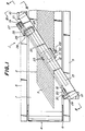
- a cutting apparatus 1 in the embodiment of the invention is intended to obliquely cut steel breaker members 2 to be used in a tire on a belt conveyor 4.
- the steel breaker member 2 includes a great number of steel cords 3 which are embedded in the steel breaker member 2 and having a constant bias angles made with a longitudinal direction of the steel breaker member 2.
- the steel breaker member 2 is cut in bias directions along the steel cords 3.
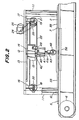
- Figs. 1 and 2 are a plan view and a side view of the cutting apparatus and the belt conveyor 4.
- the belt conveyor 4 is supported by frames 5 on both sides of the conveyor 4.
- a conveyor belt 7 of the belt conveyor 4 is extended about rollers 6 provided at front and rear ends of the frames 5.
- the belt-like steel breaker member 2 is arranged on an upper run of the conveyor belt 7 and transferred into a front direction (to the left side viewed in Fig. 1).
- the horizontal support plate 12 is provided a cutting tool traveling mechanism secured thereto and is arranged so that a longitudinal axis of the horizontal support plate 12 forms a angle with an advancing direction of the conveyor belt 7.
- the angle is coincident with a standard value of the bias angle of the steel cords 3 of the steel breaker member 2 to be transferred on the conveyor belt 7.
- a linear ball slide guide rail 13 is arranged on an underside of the horizontal support plate 12 in its longitudinal direction.
- a linear ball slide guide 14 is slidably fitted on the linear ball slide guide rail 13.
- a traveling support member 15 is fixed to an underside of the linear ball slide guide 14.
- Pivotal base plates 16 and 17 are hanged from the horizontal support plate 12 at front and rear ends on a side remote from the surface of the drawing Fig. 2. To lower ends of the pivotal base plates 16 and 17 are pivotally connected a rotating shaft 18 fixed to a driven pulley 20 and a rotating shaft 19 fixed to a driving pulley 21, respectively.
- a toothed or cog endless belt 22 extends about both the pulleys 20 and 21 and a predetermined portion of an upper run of the belt 22 is fixed to the traveling support member 15 by means of set screws 23.
- a motor 25 supported by a support plate 24 is provided on the horizontal support plate 12 in the proximity of the driving pulley 21.
- a pulley 26 is fitted on a driving shaft of the motor 25.
- a pulley 27 is fitted on an extension of the rotating shaft 19 of the driving pulley 21 in alignment thereof.
- a toothed or cog belt 28 extends about the pulleys 26 and 27.
- the motor 25 when the motor 25 is energized to rotatively drive the driving pulley 21 through the toothed belt 28, the rotation of the driving pulley 21 causes the toothed belt 22 to rotate so as to drive the traveling support member 15 along the rail 13 through the slide guide 14 at the upper end of the traveling support member 15.
- An L-shaped sensor bracket 29 extends forwardly from an inner surface of the column 11 on the side of and at the same level as the driven pulley 20.
- the bracket 29 is bent at its free end so that a surface of the bent portion is in opposition to the driven pulley 20.
- a reflection type photosensor 30 is fixed to the bent portion of the bracket 29 (Fig. 1).
- a reflecting tape 31 having reflecting and non- reflecting portions alternately arranged in eight areas of a circle equally radially divided as shown in Fig. 5.
- the reflection type photosensor 30 detects the rotated conditions of the driven pulley 20 so that the number of changes in detected value is counted to detect the moved position of the traveling support member 15.
- the above constructions are the traveling mechanism and the traveling position detecting mechanism.
- the traveling support member 15 of the traveling mechanism is provided with the cutting tool hanged therefrom.
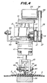
- a rail 40 of a ball slide table 42 is provided on an under surface of the traveling support member 15 and directing in a direction perpendicular to the traveling direction of the traveling support member 15.
- a cylinder 41 is fixed to an under surface of the ball slide table 42 slidably fitted on the rail 40.
- the cylinder 41 is hanged below the traveling support member 15 and slidable in a direction perpendicular to the traveling direction of the traveling support member 15.
- the cylinder 41 extends below its cylinder rod 41a whose lower end is provided with a U-shaped cutter bracket 43 fixed thereto.
- a bolt 44 horizontally extends through legs of the U-shaped cutter bracket 43 and is fixed thereto by means of nuts 46 through washers 45.
- a disc-like cutter 48 is positioned on the bolt 44 at its center by means of spacers 47 on both sides and rotatably supported.
- the cutter 48 is rotatably supported on the U-shaped cutter bracket 43 and is adapted to be raised and lowered by extending and retracting of the cylinder rod 41a. Moreover, the cutter 48 is movable in the traveling direction of the traveling support member 15, and is also movable in a direction perpendicular to the traveling direction of the traveling support member 15.
- a sensor bracket 49 is extended from a rear surface of the cylinder 41 rearwardly and its extended end is bent upwardly so as to be in opposition to a rear side surface of the traveling support member 15.
- a distance photosensor 50 is secured to the bent portion of the sensor bracket 49 in opposition to the traveling support member 15.
- the distance photosensor 50 is moved together with the cylinder 41 in the direction perpendicular to the traveling direction of the traveling support member 15 so that the photosensor 50 can detect distances between the photosensor and the traveling support member 15 at will.
- the reflection type photosensor 30 detects positions of the cutter 48 in the traveling direction
- the distance photosensor 50 detects the positions of the cutter 48 in the direction perpendicular to the traveling direction.
- Detected signals of the reflection type photosensor 30 and distance sensor 50 are inputted into a signal converter 60 for their digitization which are further inputted into a digital arithmetic unit 61 to arithmetically operate their co-ordinates.
- Results are represented in co-ordinates by means of cathode-ray tube (CRT) 62 and printer 63 and supplied to another control means 64.
- CTR cathode-ray tube
- the above is the moving mechanism for the cutter and the detecting machanism for moved positions.
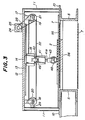
- a cutter receiving plate 55 is bridged on the frames 5 on both the sides through the support plate 10 and below and in parallel with the horizontal support plate 12 (Fig. 3).
- the cutter receiving plate 55 is arranged above and closely across the conveyor belt 7 so that the steel breaker member 2 is transferred riding on the cutter receiving plate 55.
- a permanent magnet block 56 is arranged supported by both the frames 5 at a location in opposition to the cutter receiving plate 55 through the conveyor belt 7.
- the permanent magnet block is also close to an underside the conveyor belt 7.
- the steel breaker member 2 on the cutter receiving plate 55 is downwardly attracted to be attached to the cutter receiving plate 55 by means of the magnetic force of the permanent magnet block 56 attracting the steel cords 3 embedded in the steel breaker member 2 so that the configuration of the steel breaker member 2 is properly maintained.
- the breaker member 2 transferred by the belt conveyor 4 is stopped when it has advanced a predetermined distance riding on the cutter receiving plate 55 so that a portion of the breaker member 2 to be cut is on the cutter receiving plate 55. At this instant, the portion of the breaker member 55 to be cut is held by the permanent magnet block 55.
- the motor 25 is energized so that the traveling support member 15 is moved together with the cutter 48 to a side edge of the steel breaker member 15 and is positioned thereat.
- the cutter bracket 43 is lowered by actuating the cylinder 41 so that the cutter 48 is lowered onto the side edge of the steel breaker member 2 held on the cutter receiving plate 55.
- a V-shaped cutting edge of the cutter as shown in Fig. 4 penetrates into the steel breaker member 2 and arrives at the cutter receiving plate 55 when the steel breaker member is cut off at its portion in constant with the cutting edge of the cutter 48.
- the V-shaped cutting edge of the cutter 48 penetrates between the adjacent steel cords while outer coatings of both the steel cords are carried along the cutting edge of the cutter 48 so that the steel cords are normally covered by the rubber material of the coatings.
- the breaker member is cut off when the cutting edge of the cutter 48 arrives at the cutter receiving plate 55 so that the steel cords 3 are not exposed at the cut surfaces.
- the cutter 48 is on the predetermined traveling line when it is in its raised position. If the shifting occurs as above described when lowered, the moving distance in the direction perpendicular to the traveling direction of the breaker member 2 is detected by the distance sensor 50.
- the motor 25 is energized to drive the traveling support member 15, so that the cutter cuts the breaker member 2 along the steel cord 3 between the steel cords 3 until the cutting edge of the cutter 48 arrives at a side edge on an opposite side of the breaker member 2 to complete the cutting operation.
- a cut end may be curved if the steel cords 3 are curved.
- the shifting of the cut end deviated from the predetermined traveling line is detected by the distance sensor 50 at will.
- the traveling direction of the cutter 48 is assumed as "X", and the direction perpendicular to the traveling direction is assumed as "Y”.
- Ths position of the cutter 48 in the direction Y is detected as digital counted values by the reflection type sensor 30.
- periodical counted values are selected from the digital counted values to detect the counted values
- the positions of the cutter 48 in the X direction are inputted from the distance sensor 50 into the signal converter 60 for digitization.
- the periodical counted values in the Y direction and digital informations of the respective counted values in the X direction are memorized in pairs in the digital arithmetic unit 61. These co-ordinate values are shown on a suitable scale in Fig. 7.
- the abscissa indicates the traveled positions in the direction Y and the ordinate shows deviations in the direction X.
- a dot and dash line f in parallel with the abscissa is a predetermined or expected traveling line.
- a curved line a illustrates one example of arithmetically operated results.
- the curved line a indicates the shapes of the cut sections of the breaker formed by cutting.
- a traveling line in the Y direction is substantially equally divided into twelve parts sequentially numbered 1 to 12 from which normal lines extend, a line connecting two intersecting points between the curved line a and normal lines Nos. 2 and 11 is called as b which is an approximate straight line of an actual cut line of the breaker member.
- An angle ⁇ made by the approximate straight line b and the predetermined traveling line f is arithmetically operated by the digital arithmetic unit 61.
- the cut end of the steel breaker member 2 is inclined at the angle ⁇ with the standard bias angle.
- the upper limit is located near to a terminal of the traveling and the lower limit is near at a starting position or at a center of the traveling.
- the line indicating the cut end of the breaker member is slightly curved at the center.
- the digital arithmetic unit 61 is actuated to carry out the graphing of the values, judgment of the upper and lower values, arithmetic operation of an approximate straight line of cut end and inclined angle and the like.
- the results are represented on the cathode-ray tube 62 or printed by the printer 63.
- the information of the cut ends is fed to the other control means 64.
- Fig. 8 illustrates results actually printed by the printer 63.
- the breaker member is cut substantially along the standard line through about one third of the overall length after starting of the cutting but thereafter the deviation of the cutter becomes larger.
- the cut end is curved like a chord, and when cutting is ended, the upper limit value is 1.89 mm and the inclined angle is about 0.39°.
- the inclined angle is very small of the order of 0.1°.
- the configuration of the cut ends of the steel breaker member 2 is digitally obtained so that the result can be fed-back to the preprocess or utilized for the postprocess or can be applied to various systems, thereby contributing to improve the quality of tires.
- cut lengths of the breaker member at respective measured points can also be obtained by adding feeding amounts of the breaker member.
- configurations of cut ends can be known in cutting sheet materials.
Landscapes
- Engineering & Computer Science (AREA)
- Textile Engineering (AREA)
- Mechanical Engineering (AREA)
- Tyre Moulding (AREA)
- Nonmetal Cutting Devices (AREA)
- Processing Of Stones Or Stones Resemblance Materials (AREA)
Applications Claiming Priority (2)
| Application Number | Priority Date | Filing Date | Title |
|---|---|---|---|
| JP6788/88 | 1988-01-18 | ||
| JP63006788A JP2719918B2 (ja) | 1988-01-18 | 1988-01-18 | シート状材料の切断装置 |
Publications (3)
| Publication Number | Publication Date |
|---|---|
| EP0326280A2 true EP0326280A2 (fr) | 1989-08-02 |
| EP0326280A3 EP0326280A3 (en) | 1990-05-02 |
| EP0326280B1 EP0326280B1 (fr) | 1993-07-14 |
Family
ID=11647917
Family Applications (1)
| Application Number | Title | Priority Date | Filing Date |
|---|---|---|---|
| EP89300452A Expired - Lifetime EP0326280B1 (fr) | 1988-01-18 | 1989-01-18 | Dispositif pour la découpe de matériaux en forme de feuilles |
Country Status (5)
| Country | Link |
|---|---|
| US (1) | US4965733A (fr) |
| EP (1) | EP0326280B1 (fr) |
| JP (1) | JP2719918B2 (fr) |
| DE (1) | DE68907489T2 (fr) |
| ES (1) | ES2044075T3 (fr) |
Cited By (4)
| Publication number | Priority date | Publication date | Assignee | Title |
|---|---|---|---|---|
| EP0447273A2 (fr) * | 1990-03-16 | 1991-09-18 | Bridgestone Corporation | Procédé et appareil pour couper et enrouler sur un tambour une pièce en forme de courroie |
| EP0472412A2 (fr) * | 1990-08-21 | 1992-02-26 | Bridgestone Corporation | Procédé de détection de l'état de la coupe d'une feuille en caoutchouc pourvue de cordes parallèles noyées |
| EP1188546A3 (fr) * | 2000-09-14 | 2003-06-18 | Bridgestone Corporation | Procédé et dispositif pour le réchapage de pneus |
| EP1690668A1 (fr) * | 2005-02-09 | 2006-08-16 | The Goodyear Tire & Rubber Company | Procédé et dispositif pour détecter des filaments métalliques exposés dans une bande d'élastomère |
Families Citing this family (23)
| Publication number | Priority date | Publication date | Assignee | Title |
|---|---|---|---|---|
| US5092946A (en) * | 1989-02-22 | 1992-03-03 | Bridgestone Corporation | Method for sticking a belt-like member and apparatus therefore |
| JP3396245B2 (ja) † | 1993-01-14 | 2003-04-14 | 三菱重工業株式会社 | コルゲートマシンのオーダーチェンジ方法及び装置 |
| JP2645798B2 (ja) * | 1993-07-16 | 1997-08-25 | 三ツ星ベルト株式会社 | ゴム成形体の切断装置およびその切断方法 |
| US6280548B1 (en) | 1995-01-05 | 2001-08-28 | Goodyear Tire & Rubber | Method and apparatus for building a laminate and forming a carcass subassembly for a tire |
| CA2145794A1 (fr) * | 1995-01-05 | 1996-07-06 | James Alfred Ii Benzing | Methode et appareil pour couper un stratifie d'elastomere renforce d'un cable |
| US5762740A (en) * | 1995-01-05 | 1998-06-09 | The Goodyear Tire & Rubber Company | Method for building a laminate from an assembly of tire components to form a casing |
| US6109322A (en) * | 1995-12-15 | 2000-08-29 | The Goodyear Tire & Rubber Company | Laminate composite structure for making an unvulcanized carcass for a radial ply tire as an intermediate article of manufacture |
| DE19914194C2 (de) * | 1999-03-24 | 2001-09-27 | Mannesmann Ag | Schneidmaschine mit rotierend angetriebenem Schneidmesser |
| IT1314838B1 (it) | 2000-05-31 | 2003-01-16 | Fosber Spa | Dispositivo e metodo per il cambio d'ordine in un sistema di tagliolongitudinale di un materiale nastriforme |
| DE10213148C1 (de) * | 2002-03-23 | 2003-07-03 | Jost Werke Gmbh & Co Kg | Sattelkupplung |
| BRPI0508882A (pt) * | 2004-03-18 | 2007-09-11 | Vmi Epe Holland | dispositivo de corte |
| NL1025764C2 (nl) * | 2004-03-18 | 2005-09-20 | Vmi Epe Holland | Snijinrichting. |
| US20050252354A1 (en) * | 2004-05-14 | 2005-11-17 | Tzu-Feng Tseng | Flat media cutting device |
| EP1647378B1 (fr) * | 2004-10-12 | 2010-04-14 | Fosber S.P.A. | Dispositif découpé longitudinal pour des bandes telles que des feuilles de carton ondulé |
| CN100358692C (zh) * | 2006-07-02 | 2008-01-02 | 青岛高校软控股份有限公司 | 钢丝帘布条纵裁纠偏方法及纵裁机 |
| US20100147128A1 (en) * | 2008-12-16 | 2010-06-17 | Richard David Vargo | Method and apparatus for shearing reinforced fabrics |
| FR2954727B1 (fr) * | 2009-12-24 | 2012-04-13 | Michelin Soc Tech | Procede et dispositif de mesure de l'angle de nappe avant coupe |
| JP5633676B2 (ja) * | 2010-07-06 | 2014-12-03 | 横浜ゴム株式会社 | 補強コード入りゴムシート材の切断方法及びその装置 |
| JP5620298B2 (ja) * | 2011-02-09 | 2014-11-05 | 住友ゴム工業株式会社 | ゴムストリップの切断装置および切断方法 |
| JP5924015B2 (ja) * | 2012-02-10 | 2016-05-25 | 横浜ゴム株式会社 | スチールコード入りゴムシート材の切断装置 |
| JP6236855B2 (ja) * | 2013-04-26 | 2017-11-29 | 横浜ゴム株式会社 | タイヤの製造方法 |
| JP6237167B2 (ja) * | 2013-11-29 | 2017-11-29 | 横浜ゴム株式会社 | ゴム被覆繊維シート部材の切断装置および方法 |
| CN204281570U (zh) * | 2014-12-06 | 2015-04-22 | 弗兰科瓦利亚尼 | 一种玻璃切割刀头装置 |
Citations (5)
| Publication number | Priority date | Publication date | Assignee | Title |
|---|---|---|---|---|
| US3207019A (en) * | 1961-03-11 | 1965-09-21 | Pirelli | Machine for shearing sheet material |
| FR1470761A (fr) * | 1966-03-05 | 1967-02-24 | Schloemann Ag | Dispositif d'ajustage des lames circulaires d'une cisaille à rogner les bords matés |
| US3762259A (en) * | 1972-01-03 | 1973-10-02 | Goodrich Co B F | Fabric cutting apparatus |
| US4070939A (en) * | 1976-10-06 | 1978-01-31 | The Goodyear Tire & Rubber Company | Edge control for calender covering industrial belting |
| US4667550A (en) * | 1985-12-26 | 1987-05-26 | Precision Strip Technology, Inc. | Precision slitting apparatus and method |
Family Cites Families (19)
| Publication number | Priority date | Publication date | Assignee | Title |
|---|---|---|---|---|
| BE791742A (fr) * | 1971-11-26 | 1973-05-22 | Uniroyal Inc | Appareil de coupe a longueur pour matiere decoupee en biais pour nappesde ceinture d'enveloppe de bandage pneumatique de roue |
| JPS4911107A (fr) * | 1972-05-31 | 1974-01-31 | ||
| US3789712A (en) * | 1972-10-16 | 1974-02-05 | Nrm Corp | Apparatus for severing tire ply stock and the like |
| JPS4999864A (fr) * | 1973-01-20 | 1974-09-20 | ||
| US3904471A (en) * | 1974-10-15 | 1975-09-09 | Goodyear Tire & Rubber | Tire building apparatus |
| US4210042A (en) * | 1977-11-25 | 1980-07-01 | The Goodyear Tire & Rubber Company | Method for parting ply stock between side-by-side cords or wires |
| JPS55112792A (en) * | 1979-02-23 | 1980-08-30 | Sumitomo Rubber Ind | Travelling cutting device of beltlike rubber elastic body |
| JPS58138616A (ja) * | 1982-02-13 | 1983-08-17 | Kato Hatsujo Kaisha Ltd | ガラス繊維強化成形材とその製造装置 |
| JPS58203033A (ja) * | 1982-05-24 | 1983-11-26 | Bridgestone Corp | 未加硫ゴムシ−ト切断装置 |
| JPS59196192A (ja) * | 1983-04-18 | 1984-11-07 | 株式会社ブリヂストン | コ−ドで補強された帯状ゴムシ−トの切断装置 |
| US4824515A (en) * | 1983-05-09 | 1989-04-25 | The Firestone Tire & Rubber Company | Ply applicator |
| JPS6094297A (ja) * | 1983-10-28 | 1985-05-27 | 株式会社ブリヂストン | コ−ドで補強された帯状ゴムシ−トの切断装置 |
| JPS60109895A (ja) * | 1983-11-18 | 1985-06-15 | Oji Paper Co Ltd | 感熱記録紙 |
| JPS60221294A (ja) * | 1984-04-13 | 1985-11-05 | 株式会社ブリヂストン | ゴム様材料の切泰装置 |
| JPS61109692A (ja) * | 1984-10-29 | 1986-05-28 | 株式会社 ワイゼン | 自動裁断機における切断装置 |
| JPS627533A (ja) * | 1985-07-04 | 1987-01-14 | Bridgestone Corp | タイヤ用ベルトのスチ−ルワイヤ傾斜角度検出装置 |
| JPS6213779A (ja) * | 1985-07-10 | 1987-01-22 | Mitsubishi Electric Corp | 機関点火装置 |
| JPH0698588B2 (ja) * | 1985-08-28 | 1994-12-07 | 株式会社ブリヂストン | 帯状材料の切断方法 |
| JPS6253911A (ja) * | 1985-09-02 | 1987-03-09 | Shiseido Co Ltd | 化粧料 |
-
1988
- 1988-01-18 JP JP63006788A patent/JP2719918B2/ja not_active Expired - Lifetime
-
1989
- 1989-01-18 ES ES89300452T patent/ES2044075T3/es not_active Expired - Lifetime
- 1989-01-18 US US07/298,146 patent/US4965733A/en not_active Expired - Lifetime
- 1989-01-18 DE DE89300452T patent/DE68907489T2/de not_active Expired - Fee Related
- 1989-01-18 EP EP89300452A patent/EP0326280B1/fr not_active Expired - Lifetime
Patent Citations (5)
| Publication number | Priority date | Publication date | Assignee | Title |
|---|---|---|---|---|
| US3207019A (en) * | 1961-03-11 | 1965-09-21 | Pirelli | Machine for shearing sheet material |
| FR1470761A (fr) * | 1966-03-05 | 1967-02-24 | Schloemann Ag | Dispositif d'ajustage des lames circulaires d'une cisaille à rogner les bords matés |
| US3762259A (en) * | 1972-01-03 | 1973-10-02 | Goodrich Co B F | Fabric cutting apparatus |
| US4070939A (en) * | 1976-10-06 | 1978-01-31 | The Goodyear Tire & Rubber Company | Edge control for calender covering industrial belting |
| US4667550A (en) * | 1985-12-26 | 1987-05-26 | Precision Strip Technology, Inc. | Precision slitting apparatus and method |
Cited By (9)
| Publication number | Priority date | Publication date | Assignee | Title |
|---|---|---|---|---|
| EP0447273A2 (fr) * | 1990-03-16 | 1991-09-18 | Bridgestone Corporation | Procédé et appareil pour couper et enrouler sur un tambour une pièce en forme de courroie |
| EP0447273A3 (en) * | 1990-03-16 | 1992-05-06 | Bridgestone Corporation | Method and apparatus for cutting and wrapping a belt-like member around a drum |
| EP0472412A2 (fr) * | 1990-08-21 | 1992-02-26 | Bridgestone Corporation | Procédé de détection de l'état de la coupe d'une feuille en caoutchouc pourvue de cordes parallèles noyées |
| EP0472412A3 (en) * | 1990-08-21 | 1992-04-22 | Bridgestone Corporation | Method of detecting state of cutting rubber sheet having parallel cords embedded therein |
| US5327353A (en) * | 1990-08-21 | 1994-07-05 | Bridgestone Corporation | Method of detecting state of cutting rubber sheet having parallel cords embedded therein |
| EP1188546A3 (fr) * | 2000-09-14 | 2003-06-18 | Bridgestone Corporation | Procédé et dispositif pour le réchapage de pneus |
| US6841017B2 (en) | 2000-09-14 | 2005-01-11 | Bridgestone Corporation | Re-treading method and apparatus |
| US7152648B2 (en) | 2000-09-14 | 2006-12-26 | Bridgestone Corporation | Re-treading method and apparatus |
| EP1690668A1 (fr) * | 2005-02-09 | 2006-08-16 | The Goodyear Tire & Rubber Company | Procédé et dispositif pour détecter des filaments métalliques exposés dans une bande d'élastomère |
Also Published As
| Publication number | Publication date |
|---|---|
| DE68907489T2 (de) | 1993-12-09 |
| EP0326280A3 (en) | 1990-05-02 |
| JP2719918B2 (ja) | 1998-02-25 |
| US4965733A (en) | 1990-10-23 |
| DE68907489D1 (de) | 1993-08-19 |
| ES2044075T3 (es) | 1994-01-01 |
| EP0326280B1 (fr) | 1993-07-14 |
| JPH01183396A (ja) | 1989-07-21 |
Similar Documents
| Publication | Publication Date | Title |
|---|---|---|
| EP0326280B1 (fr) | Dispositif pour la découpe de matériaux en forme de feuilles | |
| KR101140074B1 (ko) | 컷팅 장치 | |
| EP0384083B1 (fr) | Procédé et dispositif pour aligner un élément en forme de bande | |
| EP1027615B1 (fr) | Appareillage permettant d'inspecter des configurations discretes de cablage creees sur une feuille substrat en continu en matiere souple | |
| EP0434404B1 (fr) | Procédé et dispositif pour la fabrication d'une feuille en forme de ceinture | |
| US3906825A (en) | Belt shearline having metering roller | |
| JPH02221054A (ja) | ゴム引きシートの供給装置システム | |
| EP0480672A2 (fr) | Dispositif et procédé de fabrication de pneus crus | |
| EP0447273A2 (fr) | Procédé et appareil pour couper et enrouler sur un tambour une pièce en forme de courroie | |
| AU2004201631B2 (en) | Method and apparatus for centering a log | |
| EP0283750B1 (fr) | Appareil pour détacher des articles adhérant à une bande | |
| CN113894852B (zh) | 一种切割设备的控制方法 | |
| JP3020991B2 (ja) | 帯状部材巻付方法および装置 | |
| JPH0348024B2 (fr) | ||
| CN112170718A (zh) | 一种钢筋自动切割设备 | |
| JP3142594B2 (ja) | シート状材料の切断方法およびその切断装置 | |
| JPH0584849A (ja) | 帯状材料の自動供給貼付け方法 | |
| EP0501030B1 (fr) | Procédé et dispositif d'enroulement d'un matériau pour une machine de fabrication de pneus | |
| JPH11139586A (ja) | シート・パイリング装置 | |
| JPS6245136B2 (fr) | ||
| EP0326001A2 (fr) | Système de manipulation de produits à découper | |
| JPH07232211A (ja) | 連続電縫管製造設備の溶接点トラッキング方法及び連続電縫管製造設備 | |
| SU1260244A1 (ru) | Устройство дл навивки протектора ленточкой | |
| US4694580A (en) | Machine for guiding and marking plystock | |
| CN118080986A (zh) | 一种适用于横纵切割的待切割物料及其切割方法 |
Legal Events
| Date | Code | Title | Description |
|---|---|---|---|
| PUAI | Public reference made under article 153(3) epc to a published international application that has entered the european phase |
Free format text: ORIGINAL CODE: 0009012 |
|
| AK | Designated contracting states |
Kind code of ref document: A2 Designated state(s): DE ES FR GB IT |
|
| PUAL | Search report despatched |
Free format text: ORIGINAL CODE: 0009013 |
|
| AK | Designated contracting states |
Kind code of ref document: A3 Designated state(s): DE ES FR GB IT |
|
| 17P | Request for examination filed |
Effective date: 19900808 |
|
| 17Q | First examination report despatched |
Effective date: 19910909 |
|
| GRAA | (expected) grant |
Free format text: ORIGINAL CODE: 0009210 |
|
| AK | Designated contracting states |
Kind code of ref document: B1 Designated state(s): DE ES FR GB IT |
|
| REF | Corresponds to: |
Ref document number: 68907489 Country of ref document: DE Date of ref document: 19930819 |
|
| ET | Fr: translation filed | ||
| ITF | It: translation for a ep patent filed | ||
| REG | Reference to a national code |
Ref country code: ES Ref legal event code: FG2A Ref document number: 2044075 Country of ref document: ES Kind code of ref document: T3 |
|
| PLBE | No opposition filed within time limit |
Free format text: ORIGINAL CODE: 0009261 |
|
| STAA | Information on the status of an ep patent application or granted ep patent |
Free format text: STATUS: NO OPPOSITION FILED WITHIN TIME LIMIT |
|
| 26N | No opposition filed | ||
| PGFP | Annual fee paid to national office [announced via postgrant information from national office to epo] |
Ref country code: GB Payment date: 19960109 Year of fee payment: 8 |
|
| PGFP | Annual fee paid to national office [announced via postgrant information from national office to epo] |
Ref country code: DE Payment date: 19960126 Year of fee payment: 8 |
|
| PG25 | Lapsed in a contracting state [announced via postgrant information from national office to epo] |
Ref country code: GB Effective date: 19970118 |
|
| GBPC | Gb: european patent ceased through non-payment of renewal fee |
Effective date: 19970118 |
|
| PG25 | Lapsed in a contracting state [announced via postgrant information from national office to epo] |
Ref country code: DE Effective date: 19971001 |
|
| PGFP | Annual fee paid to national office [announced via postgrant information from national office to epo] |
Ref country code: FR Payment date: 19980109 Year of fee payment: 10 |
|
| PGFP | Annual fee paid to national office [announced via postgrant information from national office to epo] |
Ref country code: ES Payment date: 19980129 Year of fee payment: 10 |
|
| PG25 | Lapsed in a contracting state [announced via postgrant information from national office to epo] |
Ref country code: ES Free format text: LAPSE BECAUSE OF NON-PAYMENT OF DUE FEES Effective date: 19990119 |
|
| PG25 | Lapsed in a contracting state [announced via postgrant information from national office to epo] |
Ref country code: FR Free format text: LAPSE BECAUSE OF NON-PAYMENT OF DUE FEES Effective date: 19990930 |
|
| REG | Reference to a national code |
Ref country code: FR Ref legal event code: ST |
|
| REG | Reference to a national code |
Ref country code: ES Ref legal event code: FD2A Effective date: 20031022 |
|
| PG25 | Lapsed in a contracting state [announced via postgrant information from national office to epo] |
Ref country code: IT Free format text: LAPSE BECAUSE OF NON-PAYMENT OF DUE FEES;WARNING: LAPSES OF ITALIAN PATENTS WITH EFFECTIVE DATE BEFORE 2007 MAY HAVE OCCURRED AT ANY TIME BEFORE 2007. THE CORRECT EFFECTIVE DATE MAY BE DIFFERENT FROM THE ONE RECORDED. Effective date: 20050118 |