EP0321945B1 - Wärmeleitende Vorrichtung - Google Patents
Wärmeleitende Vorrichtung Download PDFInfo
- Publication number
- EP0321945B1 EP0321945B1 EP88121381A EP88121381A EP0321945B1 EP 0321945 B1 EP0321945 B1 EP 0321945B1 EP 88121381 A EP88121381 A EP 88121381A EP 88121381 A EP88121381 A EP 88121381A EP 0321945 B1 EP0321945 B1 EP 0321945B1
- Authority
- EP
- European Patent Office
- Prior art keywords
- heat
- pipes
- dream
- liquid
- drive pump
- Prior art date
- Legal status (The legal status is an assumption and is not a legal conclusion. Google has not performed a legal analysis and makes no representation as to the accuracy of the status listed.)
- Expired - Lifetime
Links
- 239000007788 liquid Substances 0.000 claims description 23
- 238000009825 accumulation Methods 0.000 claims description 2
- 230000008602 contraction Effects 0.000 claims description 2
- 230000005855 radiation Effects 0.000 claims description 2
- 238000010438 heat treatment Methods 0.000 description 7
- 238000001816 cooling Methods 0.000 description 3
- 238000010586 diagram Methods 0.000 description 1
- 230000008034 disappearance Effects 0.000 description 1
- 229920003023 plastic Polymers 0.000 description 1
- 230000002265 prevention Effects 0.000 description 1
- 125000000391 vinyl group Chemical group [H]C([*])=C([H])[H] 0.000 description 1
- 229920002554 vinyl polymer Polymers 0.000 description 1
- XLYOFNOQVPJJNP-UHFFFAOYSA-N water Substances O XLYOFNOQVPJJNP-UHFFFAOYSA-N 0.000 description 1
Images

Classifications
-
- H—ELECTRICITY
- H05—ELECTRIC TECHNIQUES NOT OTHERWISE PROVIDED FOR
- H05K—PRINTED CIRCUITS; CASINGS OR CONSTRUCTIONAL DETAILS OF ELECTRIC APPARATUS; MANUFACTURE OF ASSEMBLAGES OF ELECTRICAL COMPONENTS
- H05K7/00—Constructional details common to different types of electric apparatus
- H05K7/20—Modifications to facilitate cooling, ventilating, or heating
- H05K7/20218—Modifications to facilitate cooling, ventilating, or heating using a liquid coolant without phase change in electronic enclosures
- H05K7/20272—Accessories for moving fluid, for expanding fluid, for connecting fluid conduits, for distributing fluid, for removing gas or for preventing leakage, e.g. pumps, tanks or manifolds
-
- F—MECHANICAL ENGINEERING; LIGHTING; HEATING; WEAPONS; BLASTING
- F28—HEAT EXCHANGE IN GENERAL
- F28D—HEAT-EXCHANGE APPARATUS, NOT PROVIDED FOR IN ANOTHER SUBCLASS, IN WHICH THE HEAT-EXCHANGE MEDIA DO NOT COME INTO DIRECT CONTACT
- F28D15/00—Heat-exchange apparatus with the intermediate heat-transfer medium in closed tubes passing into or through the conduit walls ; Heat-exchange apparatus employing intermediate heat-transfer medium or bodies
- F28D15/02—Heat-exchange apparatus with the intermediate heat-transfer medium in closed tubes passing into or through the conduit walls ; Heat-exchange apparatus employing intermediate heat-transfer medium or bodies in which the medium condenses and evaporates, e.g. heat pipes
Definitions
- the present invention relates to a heat conducting device which can conveniently be used for cooling or heating the portions in which a heat pipe cannot be utilized sufficiently, such as small portions of electronic circuits or precision mechanical equipments or soft articles such as hot carpets or warm cloths.
- the above-described "Dream Pipe” is characterized in that heat can be kinetically conducted through a pipe by using a boundary layer formed on the wall of a pipe by forward or rearward moving the liquid in the pipe with vibration applied.to the pipe.
- the pipes of the type described above can exhibit advantages, with respect to heat pipes, that the operating temperature can be selected optionally, only a low pressure is needed to operate such pipes, the operation start and stop can be freely conducted, both wick device and the vacuum operation are not necessary, the structure is simple, and thereby such pipes can be easily manufactured.
- the "Dream Pipe” cannot be operated only by a temperature difference, the temperature difference though being sufficient to operate the heat pipes. Therefore, an outside power for applying vibration to the liquid such as an electric motor or a compressor has to be provided.
- An object of the present invention is to provide a heat conducting device in which the characteristics of the "Dream Pipe" cannot be deteriorated, and capable of being individually operated by only a temperature difference, similarly to the heat pipes.
- a heat conducting device comprising a heat drive pump for generating steam bubbles for circulating a liquid in a circulating conduit by growth and contraction of the steam bubbles, and dream pipes for spatially transporting heat without liquid circulation by repeated heat accumulation and radiation in boundary layers formed on the wall surfaces of the dream pipes by forward and rearward movement of the liquid under vibration applied thereto, said dream pipes being connected at one of the ends thereof to the circulating conduit while the other ends of the dream pipes being provided with expandable means, whereby in operation said forward and rearward movement of the liquid in said dream pipes is only caused by an intermittent circulation of the liquid in the circulating conduit caused by said heat drive pump.
- a heat drive pump is principally known from EP-A-0 169 550 as a device for circulating a heat transporting liquid in a conduit.
- each dream pipe can be opened to another circulating conduit connected to said one circulating conduit including said heat drive pump by means of a pressure conducting means.
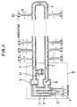
- Fig. 1 illustrates an embodiment of the present invention, wherein a heat conducting device is used as a heating device.
- the portion surrounded by a dashed line serves as a heat drive pump 8, this heat drive pump 8 being provided with a heating portion 1 which includes a cavity portion 2 so that heat delivered by a heat source in the heating potion 1 is absorbed and thereby steam bubbles are generated in the cavity portion 2 disposed inside the heating portion 1.
- the thus-generated bubbles grow and reach a condensing pipe 4 disposed in a gas-liquid converter chamber 3, wherein the bubbles are immediately cooled down, condensed, and disappears.
- the heat drive pump 8 circulates the liquid through the outer pipe 7, and as well supplies heat, absorbed by the heating portion 1 thereof, to the outer pipe 7.
- a multiplicity of dream pipes 9 having an opened end thereof are secured to the thus-formed outer pipe 7, the dream pipes 9 each having a small-sized diaphragm type accumulator 10.
- boundary layers generated on the pipe walls in the dream pipes 9 gradually conduct the heat in the outer pipe 7 toward the diaphragm type accumulators 10 disposed at the front ends of the dream pipes 9 with heat supplied and received between the boundary layers and the liquid which is being forward and rearward moved. Through these pipe walls, heat can be delivered outside.
- a water hammer prevention stopper valve 11 is provided for the purpose of avoiding pressure rise due to inertia of the liquid in the outer pipe 7 generated when the stopper valve of the heat drive pump 8 is operated. Although there is a variety of types of the heat drive pump, any one only satisfying the required factor of pressure change can be applied.
- a structure may be employed in that a partial portion of the outer pipe is expanded so as to be a chamber to which each end of the dream pipes is opened.
- the diaphragm type accumulators 10 may be in the form of a bag made of rubber or soft plastic.
- the outer pipes 7 and the dream pipes 9 may be made of flexible vinyl pipes or the like.
- arrows disposed below the heating portion 1 designate the directions of the heat.
- arrows disposed around the dream pipes 9 and the accumulators 10 also designate the directions of heat which has been radiated toward the outside thermal load.
- Fig. 2 illustrates another embodiment of the present invention in which the device according to the present invention is used as a cooling device that is characterized in that heat is removed from a thermal load 12 and the thus-removed heat is arranged to be radiated outside the thermal load 12 by using a load radiating fin 13.
- the portion surrounded by a dashed line serves as a heat drive pump 8 which has a heat source provided separately from the thermal load. Since the outer pipe 7 passes through a pump radiating device 14, heat from the heat drive pump 8 is conducted to this pump radiating device 14 by the liquid circulation.
- the dream pipes 17 connected to the dream pipe radiating chamber 16 and diaphragm type accumulators 18 thereof are operated.
- the dream pipes 17 and the diaphragm type accumulator thereof are disposed in the thermal load 12 so that heat in this thermal load 12 is conducted to the heat radiating chamber 16 from which the heat is delivered by the radiating fin 13.
- a flow-rate distribution valve 19 is disposed between the outer pipe 7 and the diaphragm type pressure conducting device 15 and is connected between them and is as well connected to a sub-accumulator 20.
- flow rate upon the pressure change in the heat drive pump can be as needs distributed between the diaphragm type pressure conducting device 15 and the sub-accumulator 20. Consequently, the operating force by the dream pipes can be controlled for the purpose of controlling the amount of heat conducted through the dream pipes.
Landscapes
- Engineering & Computer Science (AREA)
- Microelectronics & Electronic Packaging (AREA)
- Physics & Mathematics (AREA)
- Thermal Sciences (AREA)
- Life Sciences & Earth Sciences (AREA)
- Sustainable Development (AREA)
- Mechanical Engineering (AREA)
- General Engineering & Computer Science (AREA)
- Electromagnetic Pumps, Or The Like (AREA)
- Reciprocating Pumps (AREA)
- Central Heating Systems (AREA)
Claims (2)
- Wärmeübertragungsvorrichtung, aufweisend
eine wärmegetriebene Pumpe (8) zur Erzeugung von Dampfblasen zur Zirkulation einer Flüssigkeit in einer Umlaufleitung (7) durch Wachstum und Kontraktion der Dampfblasen, und
Traumrohre (9,17) zum räumlichen Transport von Wärme ohne Flüssigkeitszirkulation durch wiederholte Wärmespeicherung und -abgabe an an den Wandflächen der Traumrohre gebildeten Grenzschichten durch Vor- und Rückwärtsbewegung der Flüssigkeit unter einer daran angelegten Schwingung, welche Traumrohre mit ihren einen Enden mit der Umlaufleitung (7) in Verbindung stehen, während die anderen Enden der Traumrohre (9,17) mit ausdehnbaren Einrichtungen (10,18) versehen sind, wobei beim Betrieb die Vor- und Rückwärtsbewegung der Flüssigkeit in den Traumrohren (9,17) nur durch eine intermittierende Zirkulation der Flüssigkeit in der Umlaufleitung (7), die durch die wärmegetriebene Pumpe (8) hervorgerufen wird, bewirkt wird. - Wärmeübertragungsvorrichtung nach Anspruch 1, wonach jedes Traumrohr (17) in eine zweite Umlaufleitung (16) einmündet, die mit der einen die wärmegetriebene Pumpe (8) enthaltenden Umlaufleitung (7) durch eine Druckübertragungseinrichtung (15) verbunden ist.
Applications Claiming Priority (2)
| Application Number | Priority Date | Filing Date | Title |
|---|---|---|---|
| JP324819/87 | 1987-12-22 | ||
| JP62324819A JP2594446B2 (ja) | 1987-12-22 | 1987-12-22 | 熱伝達装置 |
Publications (3)
| Publication Number | Publication Date |
|---|---|
| EP0321945A2 EP0321945A2 (de) | 1989-06-28 |
| EP0321945A3 EP0321945A3 (en) | 1990-01-17 |
| EP0321945B1 true EP0321945B1 (de) | 1994-08-17 |
Family
ID=18170025
Family Applications (1)
| Application Number | Title | Priority Date | Filing Date |
|---|---|---|---|
| EP88121381A Expired - Lifetime EP0321945B1 (de) | 1987-12-22 | 1988-12-21 | Wärmeleitende Vorrichtung |
Country Status (4)
| Country | Link |
|---|---|
| US (1) | US4881593A (de) |
| EP (1) | EP0321945B1 (de) |
| JP (1) | JP2594446B2 (de) |
| DE (1) | DE3851135T2 (de) |
Families Citing this family (8)
| Publication number | Priority date | Publication date | Assignee | Title |
|---|---|---|---|---|
| US5107920A (en) * | 1990-03-30 | 1992-04-28 | The United States Of America As Represented By The Administrator Of The National Aeronautics And Space Administration | Heat exchanger with oscillating flow |
| US6856037B2 (en) * | 2001-11-26 | 2005-02-15 | Sony Corporation | Method and apparatus for converting dissipated heat to work energy |
| JP4486844B2 (ja) * | 2003-05-21 | 2010-06-23 | 株式会社Kri | 熱輸送装置 |
| JP4653082B2 (ja) * | 2004-03-30 | 2011-03-16 | 謙治 岡安 | 携帯式熱伝達装置 |
| SE535370C2 (sv) * | 2009-08-03 | 2012-07-10 | Skanska Sverige Ab | Anordning och metod för lagring av termisk energi |
| WO2016121778A1 (ja) * | 2015-01-27 | 2016-08-04 | 古河電気工業株式会社 | 蓄熱容器及び蓄熱容器を備えた蓄熱装置 |
| JP6757613B2 (ja) * | 2016-07-27 | 2020-09-23 | 古河電気工業株式会社 | 蓄熱システム、蓄熱容器、蓄熱容器を用いた蓄熱装置、及び蓄熱装置を用いた暖気装置 |
| TWI688326B (zh) * | 2018-01-17 | 2020-03-11 | 緯創資通股份有限公司 | 冷卻液補充機構及具有冷卻液補充機構的冷卻循環系統及電子設備 |
Citations (1)
| Publication number | Priority date | Publication date | Assignee | Title |
|---|---|---|---|---|
| EP0169550A2 (de) * | 1984-07-24 | 1986-01-29 | Kenji Okayasu | Wärmetransportvorrichtung |
Family Cites Families (11)
| Publication number | Priority date | Publication date | Assignee | Title |
|---|---|---|---|---|
| GB897785A (en) * | 1959-07-29 | 1962-05-30 | Lucien Grillet | Improvements in or relating to space heating systems |
| US3929305A (en) * | 1972-10-27 | 1975-12-30 | Nasa | Heat exchanger system and method |
| US4120172A (en) * | 1977-05-05 | 1978-10-17 | The United States Of America As Represented By The United States Department Of Energy | Heat transport system |
| JPS5430552A (en) * | 1977-08-12 | 1979-03-07 | Hitachi Ltd | Boiling cooling apparatus |
| US4212593A (en) * | 1979-01-25 | 1980-07-15 | Utah State University Foundation | Heat-powered water pump |
| US4450690A (en) * | 1983-01-10 | 1984-05-29 | Clark Jr Robert W | Thermally powered, gravitationally assisted heat transfer systems |
| JPS6131679A (ja) * | 1984-07-24 | 1986-02-14 | Kenji Okayasu | 熱駆動ポンプ |
| US4590993A (en) * | 1984-10-23 | 1986-05-27 | University Of Florida | Heat transfer device for the transport of large conduction flux without net mass transfer |
| JP2703883B2 (ja) * | 1985-11-21 | 1998-01-26 | 日本電気株式会社 | Misトランジスタ及びその製造方法 |
| JPS62122171A (ja) * | 1985-11-22 | 1987-06-03 | Hitachi Ltd | 薄膜トランジスタ |
| JPH0718408B2 (ja) * | 1986-06-23 | 1995-03-06 | 謙治 岡安 | 熱駆動ポンプ |
-
1987
- 1987-12-22 JP JP62324819A patent/JP2594446B2/ja not_active Expired - Fee Related
-
1988
- 1988-12-21 DE DE3851135T patent/DE3851135T2/de not_active Expired - Fee Related
- 1988-12-21 EP EP88121381A patent/EP0321945B1/de not_active Expired - Lifetime
- 1988-12-22 US US07/288,611 patent/US4881593A/en not_active Expired - Lifetime
Patent Citations (1)
| Publication number | Priority date | Publication date | Assignee | Title |
|---|---|---|---|---|
| EP0169550A2 (de) * | 1984-07-24 | 1986-01-29 | Kenji Okayasu | Wärmetransportvorrichtung |
Non-Patent Citations (1)
| Title |
|---|
| Technology Review Diagram : Omnigraphics, vol. 88-6, Aug./Sept. 1985, p. 64 ; D. Kennedy : "Dream Pipe". * |
Also Published As
| Publication number | Publication date |
|---|---|
| EP0321945A2 (de) | 1989-06-28 |
| DE3851135T2 (de) | 1995-01-05 |
| JP2594446B2 (ja) | 1997-03-26 |
| US4881593A (en) | 1989-11-21 |
| JPH01167595A (ja) | 1989-07-03 |
| DE3851135D1 (de) | 1994-09-22 |
| EP0321945A3 (en) | 1990-01-17 |
Similar Documents
| Publication | Publication Date | Title |
|---|---|---|
| JP2859927B2 (ja) | 冷却装置および温度制御装置 | |
| US7061763B2 (en) | Cabinet cooling | |
| EP0321945B1 (de) | Wärmeleitende Vorrichtung | |
| US7866164B2 (en) | Cooling and heating systems and methods utilizing thermo-electric devices | |
| CA2178981A1 (en) | Heat Exchanger and Heat Pump Circuit | |
| EP0321944B1 (de) | Kühlungsvorrichtung für eine elektronische Anlage | |
| US4750543A (en) | Pumped two-phase heat transfer loop | |
| EP0855566A3 (de) | Integrierter Wärmetauscher | |
| US4664177A (en) | Pumped two-phase heat transfer loop | |
| JP2010502163A (ja) | 自己冷却式電気モータ | |
| JPH02245401A (ja) | エアモータの凍結防止装置 | |
| JPH0961074A (ja) | クローズド温度制御システム | |
| TWI767331B (zh) | 脈衝迴路熱交換器與其製造方法 | |
| US3805518A (en) | Apparatus for controlling thermal growth in condensers | |
| KR100352439B1 (ko) | 신체에 착용이 가능한 개인용 냉난방장치 | |
| EP0663263B1 (de) | Anlage zum Vermeiden von thermischen Verformungen einer Werkzeugmaschine | |
| KR930023696A (ko) | 축열식 가열장치, 축열소자 및 그것을 이용한 방석, 구두, 조끼 각로 매트리스 및 모포 | |
| JPS6141850A (ja) | 地熱水利用の熱水造成設備 | |
| JPH08611Y2 (ja) | 熱駆動ポンプ | |
| JP3256795B2 (ja) | 金型の加熱または冷却装置 | |
| PL446746A1 (pl) | Układ urządzenia chłodniczego strumienicowego | |
| KR20100055593A (ko) | 열전모듈이 구비된 차량용 공조장치 | |
| JPH06750A (ja) | 熱変位防止装置およびそれを備えた工作機械 | |
| JPS6314162Y2 (de) | ||
| KR101842367B1 (ko) | 열전소자를 이용한 저전력 냉난방장치 |
Legal Events
| Date | Code | Title | Description |
|---|---|---|---|
| PUAI | Public reference made under article 153(3) epc to a published international application that has entered the european phase |
Free format text: ORIGINAL CODE: 0009012 |
|
| AK | Designated contracting states |
Kind code of ref document: A2 Designated state(s): DE FR GB |
|
| PUAL | Search report despatched |
Free format text: ORIGINAL CODE: 0009013 |
|
| AK | Designated contracting states |
Kind code of ref document: A3 Designated state(s): DE FR GB |
|
| RHK1 | Main classification (correction) |
Ipc: H01L 23/42 |
|
| 17P | Request for examination filed |
Effective date: 19900613 |
|
| 17Q | First examination report despatched |
Effective date: 19920807 |
|
| GRAA | (expected) grant |
Free format text: ORIGINAL CODE: 0009210 |
|
| AK | Designated contracting states |
Kind code of ref document: B1 Designated state(s): DE FR GB |
|
| REF | Corresponds to: |
Ref document number: 3851135 Country of ref document: DE Date of ref document: 19940922 |
|
| ET | Fr: translation filed | ||
| PLBE | No opposition filed within time limit |
Free format text: ORIGINAL CODE: 0009261 |
|
| STAA | Information on the status of an ep patent application or granted ep patent |
Free format text: STATUS: NO OPPOSITION FILED WITHIN TIME LIMIT |
|
| 26N | No opposition filed | ||
| REG | Reference to a national code |
Ref country code: GB Ref legal event code: IF02 |
|
| PGFP | Annual fee paid to national office [announced via postgrant information from national office to epo] |
Ref country code: DE Payment date: 20031205 Year of fee payment: 16 |
|
| PGFP | Annual fee paid to national office [announced via postgrant information from national office to epo] |
Ref country code: FR Payment date: 20041022 Year of fee payment: 17 |
|
| PGFP | Annual fee paid to national office [announced via postgrant information from national office to epo] |
Ref country code: GB Payment date: 20041215 Year of fee payment: 17 |
|
| PG25 | Lapsed in a contracting state [announced via postgrant information from national office to epo] |
Ref country code: DE Free format text: LAPSE BECAUSE OF NON-PAYMENT OF DUE FEES Effective date: 20050701 |
|
| PG25 | Lapsed in a contracting state [announced via postgrant information from national office to epo] |
Ref country code: GB Free format text: LAPSE BECAUSE OF NON-PAYMENT OF DUE FEES Effective date: 20051221 |
|
| GBPC | Gb: european patent ceased through non-payment of renewal fee |
Effective date: 20051221 |
|
| PG25 | Lapsed in a contracting state [announced via postgrant information from national office to epo] |
Ref country code: FR Free format text: LAPSE BECAUSE OF NON-PAYMENT OF DUE FEES Effective date: 20060831 |
|
| REG | Reference to a national code |
Ref country code: FR Ref legal event code: ST Effective date: 20060831 |