EP0321944B1 - Kühlungsvorrichtung für eine elektronische Anlage - Google Patents
Kühlungsvorrichtung für eine elektronische Anlage Download PDFInfo
- Publication number
- EP0321944B1 EP0321944B1 EP88121380A EP88121380A EP0321944B1 EP 0321944 B1 EP0321944 B1 EP 0321944B1 EP 88121380 A EP88121380 A EP 88121380A EP 88121380 A EP88121380 A EP 88121380A EP 0321944 B1 EP0321944 B1 EP 0321944B1
- Authority
- EP
- European Patent Office
- Prior art keywords
- heat
- flow passage
- electronic equipment
- liquid
- cyclic flow
- Prior art date
- Legal status (The legal status is an assumption and is not a legal conclusion. Google has not performed a legal analysis and makes no representation as to the accuracy of the status listed.)
- Expired - Lifetime
Links
- 238000001816 cooling Methods 0.000 title claims description 17
- 125000004122 cyclic group Chemical group 0.000 claims description 27
- 239000012530 fluid Substances 0.000 claims description 4
- 239000007788 liquid Substances 0.000 description 28
- 239000000758 substrate Substances 0.000 description 7
- XLYOFNOQVPJJNP-UHFFFAOYSA-N water Substances O XLYOFNOQVPJJNP-UHFFFAOYSA-N 0.000 description 6
- 208000028659 discharge Diseases 0.000 description 4
- 230000005611 electricity Effects 0.000 description 4
- 230000002265 prevention Effects 0.000 description 3
- RYGMFSIKBFXOCR-UHFFFAOYSA-N Copper Chemical compound [Cu] RYGMFSIKBFXOCR-UHFFFAOYSA-N 0.000 description 2
- 229910052802 copper Inorganic materials 0.000 description 2
- 239000010949 copper Substances 0.000 description 2
- 238000010438 heat treatment Methods 0.000 description 2
- 239000000463 material Substances 0.000 description 2
- 230000005855 radiation Effects 0.000 description 2
- 239000000126 substance Substances 0.000 description 2
- 239000002918 waste heat Substances 0.000 description 2
- 230000005540 biological transmission Effects 0.000 description 1
- 239000004020 conductor Substances 0.000 description 1
- 230000001351 cycling effect Effects 0.000 description 1
- 230000000694 effects Effects 0.000 description 1
- 239000002184 metal Substances 0.000 description 1
- 229910052751 metal Inorganic materials 0.000 description 1
- 238000000034 method Methods 0.000 description 1
- 239000000203 mixture Substances 0.000 description 1
- 239000004033 plastic Substances 0.000 description 1
- 238000005086 pumping Methods 0.000 description 1
- 230000000717 retained effect Effects 0.000 description 1
Images

Classifications
-
- H—ELECTRICITY
- H05—ELECTRIC TECHNIQUES NOT OTHERWISE PROVIDED FOR
- H05K—PRINTED CIRCUITS; CASINGS OR CONSTRUCTIONAL DETAILS OF ELECTRIC APPARATUS; MANUFACTURE OF ASSEMBLAGES OF ELECTRICAL COMPONENTS
- H05K7/00—Constructional details common to different types of electric apparatus
- H05K7/20—Modifications to facilitate cooling, ventilating, or heating
- H05K7/20218—Modifications to facilitate cooling, ventilating, or heating using a liquid coolant without phase change in electronic enclosures
- H05K7/20272—Accessories for moving fluid, for expanding fluid, for connecting fluid conduits, for distributing fluid, for removing gas or for preventing leakage, e.g. pumps, tanks or manifolds
-
- H—ELECTRICITY
- H05—ELECTRIC TECHNIQUES NOT OTHERWISE PROVIDED FOR
- H05K—PRINTED CIRCUITS; CASINGS OR CONSTRUCTIONAL DETAILS OF ELECTRIC APPARATUS; MANUFACTURE OF ASSEMBLAGES OF ELECTRICAL COMPONENTS
- H05K7/00—Constructional details common to different types of electric apparatus
- H05K7/20—Modifications to facilitate cooling, ventilating, or heating
- H05K7/20536—Modifications to facilitate cooling, ventilating, or heating for racks or cabinets of standardised dimensions, e.g. electronic racks for aircraft or telecommunication equipment
- H05K7/20627—Liquid coolant without phase change
- H05K7/20636—Liquid coolant without phase change within sub-racks for removing heat from electronic boards
Definitions
- the present invention relates to a cooling device for electronic equipments for use in aircrafts or high speed computers displaying a high mounting density and involving a necessity for its size to be reduced.
- a liquid cooling device of the type described above needs to be provided with a liquid cycling pump, a motor for driving the pump, and electricity. Therefore, such type of device cannot be employed as a small sized device, and furthermore, it cannot be preferably used on the viewpoints of reliability, electricity consumption and noise reduction.
- the invention is to provide a type of a electronic equipment cooling device in which the waste heat from one electronic equipment serves for cooling another electronic component without the necessity of using such specific substances of the prior system.
- the cooling device according to the invention is set out in the appended claim and comprises: a first cyclic flow passage including a heat driven pump, heat emitting means to provide heat to the pump, and a first radiator or heat exchanger for cooling said heat driven pump, and a second cyclic flow passage including the electronic equipment to be cooled, a second radiator or heat exchanger and two stopper valves permitting a flow of fluid through the second heat exchanger and the electronic equipment in a single direction only, said first and second cyclic flow passages being separated from each other by a pressure transmitting means effecting circulation of the fluid in the second cyclic flow passage.
- the cooling device comprises two independent cyclic flow passages in which one of the passages include a heat driven pump in which steam bubbles in a manner similar to a heat transporting devices according to the EP-A-169 550 are generated for increasing the pressure to provide a pumping effect in this cyclic flow passage.
- Fig. 1 illustrates a cooling device according to an embodiment of the present invention.
- Five power transistors insulated by an electricity insulating sheet and arranged to serve as an electric power source are secured to a heat accumulating plate 1 made of a material having a high heat conductivity such as copper.
- the upper portion of the heat accumulating plate 1 also serves as a recessed portion 3 for a heating portion of the heat driven pump P.
- Heat from the power transistors 2 is accumulated by the heat accumulating plate 1 to the recessed portion 3 in which a part of the inner liquid is vaporized. As a result, steam bubbles are generated and grown in a gas-liquid converting chamber 4.
- liquid in the gas-liquid converting chamber 4 opens a primary discharge stopper valve 5 by a degree corresponding to the grown capacity of the steam bubbles, and the liquid is discharged into a primary outlet pipe 6.
- a primary suction stopper valve 7 is closed so that the liquid corresponding to the grown capacity of the steam bubbles makes a diaphragm of a pressure conducting device 8 project upward.
- the primary discharge stopper valve 5 When the grown steam bubbles then disappear due to being cooled in the gas-liquid converting chamber 4, the primary discharge stopper valve 5 is closed, while the primary suction stopper valve is opened so that the liquid which has been cooled by a first radiator 9 is, via a primary inlet pipe 10, introduced into the gas-liquid converting chamber 4 of the heat driven pump P. Simultaneously, the diaphragm which has projected upward restores its original state. As described above, liquid in the primary cyclic flow passage including the heat driven pump P cycles through the flow passage with heat generated by the power transistors 3 transferred to the outside primary radiator 9, and moves the diaphragm of the pressure conducting device 8.
- a water hammer prevention stopper valve 17 disposed outside the two stopper valves in the secondary cyclic flow passage and in parallel to the heat accumulating portion 15 in the electronic equipment serves to absorb the water hammer generated when the stopper valves are opened and closed.
- Such water hammer prevention stopper valve can effectively prevent the water hammer in a case of a long cyclic flow passage.
- the water hammer prevention stopper valve may be provided in the primary cyclic flow passage side including the heat driven pump. However, this cooling device can operate if such water hammer is not provided.
- the cyclic flow passage comprises pipes made of metal or the like
- an accumulator needs to be provided in the secondary cyclic flow passage.
- Such accumulator can be replaced by a rubber or a soft plastic pipe used in part in the flow passage.
- use of easily vaporizable liquid, with respect to liquid used in the secondary flow passage, in a primary flow passage can cause for the diaphragm to operate further actively.
- the flow passage which connects the primary flow passage to the diaphragm may be disposed any position in the primary flow passage. However, it is preferable for this flow passage to be disposed between the outlet of the primary side radiator and the primary side suction stopper valve in order to make heat transmission from the heat driven pump to the diaphragm difficult.
- the secondary radiator in the secondary flow passage may also be disposed in the secondary flow passage.
- the secondary radiator it is advantageous for the secondary radiator to be disposed between the secondary suction stopper valve which is disposed at the outlet from the diaphragm and the heat accumulating portion in the electronic equipment on the viewpoint that cooled liquid from the outlet of the radiator can be supplied to the inside portion of the electronic equipment.
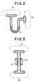
- a U-shaped pipe is used to establish a connection between the primary cyclic flow passage 19 and the secondary cyclic flow passage 20 and liquid 21 having a larger density than that used in the primary side and the secondary side and having a characteristic not to be mixed with the liquid in both sides is enclosed in this above-described U-shaped pipe.
- a structure as shown in Fig. 3 may be employed such that magnetic liquid 22 is enclosed between the liquid in the primary side and the secondary side and the thus enclosed magnetic liquid is retained at a predetermined position by a permanent magnet 23.
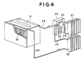
- Fig. 4 is a perspective view of another embodiment of the present invention in which the state that the device according to the present invention is applied to an actual equipment is illustrated.
- a heat source and a primary radiation system are formed by a driving portion 24 which comprises the heat driven pump, electric power source unit 25 and power transistors 26 serving as a heat source, primary radiator 27 and a primary cyclic flow passage pipe 28.
- a secondary radiation system is formed by a secondary cyclic flow passage pipe 29 which passes from the secondary radiator 30, via heat accumulating portion 31 in the electronic equipment, to a driving portion.
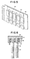
- a multiplicity of printed substrates 33 as shown in Fig. 5 are provided in the electronic equipment in such a manner that the printed substrates 33 are coupled with the heat accumulating portion 31.
- Fig. 5 illustrates the printed substrates 33 manufactured so as to be used in a high-density mounted manner.
- Each of the electronic devices 32 is soldered in such a manner that the same is positioned in contact with a bus bar 34 made of a material having an excellent thermal conductivity such as copper. As a result, heat generated from each of the electronic devices is transmitted to the bus bar 34.
- Fig. 6 is a cross-sectional view of the guide portion of the printed substrate shown in Fig. 4.
- the printed substrate 33 is abutted by a spring 35 against the bus bar 34 on the wall of the guide portion which is made of an excellent heat conductive material in the heat accumulating portion 31 in the electronic equipment.
- heat can be transmitted to the heat accumulating portion 31. Since a cyclic flow passage 36 is provided in this heat accumulating portion 31, heat of the heat accumulating portion 31 is discharged by cyclic liquid enclosed in the cyclic flow passage 36.
- the cooling device according to the present invention does not need any additional energy source such as electricity since it is operated by heat generated from heating devices in an electric source or the like. Furthermore, since the device according to the present invention does not employ a conducting motor, noise cannot be generated. In addition, since the size of this device can be reduced and structure of the same can be simplified, an excellent reliability can be obtained and application to small sized electronic equipments can be easily performed.
Landscapes
- Engineering & Computer Science (AREA)
- Microelectronics & Electronic Packaging (AREA)
- Physics & Mathematics (AREA)
- Thermal Sciences (AREA)
- Aviation & Aerospace Engineering (AREA)
- Cooling Or The Like Of Electrical Apparatus (AREA)
- Cooling Or The Like Of Semiconductors Or Solid State Devices (AREA)
Claims (1)
- Kühlvorrichtung für eine elektronische Apparatur umfassend: eine erste Umlaufströmungspassage (6,10,19,28), die eine wärmegetriebene Pumpe (P), eine wärmeabgebende Einrichtung (1,2), welche Wärme an die Pumpe liefert, und einen ersten Radiator oder Wärmetauscher (9,27) zur Kühlung der wärmegetriebenen Pumpe enthält, und eine zweite Umlaufströmungspassage (13,16,18,20,29), die die zu kühlende elektronische Apparatur, einen zweiten Radiator oder Wärmetauscher (14,30) und zwei Absperrventile (11,12) enthält, die eine Fluidströmung durch den zweiten Wärmetauscher und die elektronische Apparatur in nur einer einzigen Richtung erlauben, wobei die erste und zweite Umlaufströmungspassage durch eine einen Umlauf des Fluides in der zweiten Umlaufströmungspassage (28) bewirkende Druckübertragungseinrichtung (8,21,22,23) voneinander getrennt sind.
Applications Claiming Priority (2)
| Application Number | Priority Date | Filing Date | Title |
|---|---|---|---|
| JP62324820A JP2519959B2 (ja) | 1987-12-22 | 1987-12-22 | 電子機器冷却装置 |
| JP324820/87 | 1987-12-22 |
Publications (3)
| Publication Number | Publication Date |
|---|---|
| EP0321944A2 EP0321944A2 (de) | 1989-06-28 |
| EP0321944A3 EP0321944A3 (en) | 1990-01-17 |
| EP0321944B1 true EP0321944B1 (de) | 1994-08-10 |
Family
ID=18170038
Family Applications (1)
| Application Number | Title | Priority Date | Filing Date |
|---|---|---|---|
| EP88121380A Expired - Lifetime EP0321944B1 (de) | 1987-12-22 | 1988-12-21 | Kühlungsvorrichtung für eine elektronische Anlage |
Country Status (4)
| Country | Link |
|---|---|
| US (1) | US4930570A (de) |
| EP (1) | EP0321944B1 (de) |
| JP (1) | JP2519959B2 (de) |
| DE (1) | DE3851044T2 (de) |
Families Citing this family (23)
| Publication number | Priority date | Publication date | Assignee | Title |
|---|---|---|---|---|
| US5285347A (en) * | 1990-07-02 | 1994-02-08 | Digital Equipment Corporation | Hybird cooling system for electronic components |
| US5127471A (en) * | 1991-07-26 | 1992-07-07 | Weislogel Mark M | Pulse thermal energy transport/storage system |
| US5257660A (en) * | 1992-06-30 | 1993-11-02 | Aaron J. Cargile | Thermal transport oscillator |
| US5523640A (en) * | 1994-04-22 | 1996-06-04 | Cincinnati Milacron Inc. | Liquid cooling for electrical components of a plastics processing machine |
| US5655598A (en) * | 1995-09-19 | 1997-08-12 | Garriss; John Ellsworth | Apparatus and method for natural heat transfer between mediums having different temperatures |
| US6789611B1 (en) * | 2000-01-04 | 2004-09-14 | Jia Hao Li | Bubble cycling heat exchanger |
| KR20020034613A (ko) * | 2000-11-02 | 2002-05-09 | 김은태 | 전기/전자장비용 부품 냉각장치 |
| US6856037B2 (en) * | 2001-11-26 | 2005-02-15 | Sony Corporation | Method and apparatus for converting dissipated heat to work energy |
| US20030234296A1 (en) * | 2002-05-14 | 2003-12-25 | Rixen James M. | Heating system |
| US20070034702A1 (en) * | 2002-05-14 | 2007-02-15 | Rixen James M | Heating system |
| TWI286874B (en) † | 2002-06-12 | 2007-09-11 | Sumitomo Heavy Industries | Cooling mechanism for cooling electric driving part of injection molding machine and cooling method for the same |
| EP1709683A1 (de) * | 2004-01-22 | 2006-10-11 | Koninklijke Philips Electronics N.V. | Verfahren und einrichtung zum kühlen mindestens einer elektronischen einrichtung |
| JP4653082B2 (ja) * | 2004-03-30 | 2011-03-16 | 謙治 岡安 | 携帯式熱伝達装置 |
| CN1940453A (zh) * | 2005-09-29 | 2007-04-04 | 鸿富锦精密工业(深圳)有限公司 | 热管 |
| CA2691469A1 (en) * | 2006-10-04 | 2008-04-10 | Sensorjet Holdings Limited | Fire suppression |
| US7486515B2 (en) | 2007-02-09 | 2009-02-03 | Delphi Technologies, Inc. | Fluid circulator for fluid cooled electronic device |
| US20080283221A1 (en) * | 2007-05-15 | 2008-11-20 | Christian Blicher Terp | Direct Air Contact Liquid Cooling System Heat Exchanger Assembly |
| DE102011109594A1 (de) * | 2011-08-05 | 2013-02-07 | Connaught Electronics Ltd. | Vorrichtung mit einem Gehäuse, zumindest zwei Leiterplatten und zumindest einem Wärmeableitelement |
| KR20150111422A (ko) * | 2014-03-21 | 2015-10-06 | 엘에스산전 주식회사 | 자동차용 전장 부품 케이스 |
| CN109588001B (zh) * | 2017-09-28 | 2024-05-24 | 泽鸿(广州)电子科技有限公司 | 双回路液冷系统 |
| TWI694563B (zh) * | 2017-09-28 | 2020-05-21 | 雙鴻科技股份有限公司 | 雙迴路液冷系統 |
| TWI688326B (zh) * | 2018-01-17 | 2020-03-11 | 緯創資通股份有限公司 | 冷卻液補充機構及具有冷卻液補充機構的冷卻循環系統及電子設備 |
| CN112908628A (zh) * | 2021-02-04 | 2021-06-04 | 广州南柯梦网络科技有限公司 | 一种安全散热的变压器 |
Family Cites Families (16)
| Publication number | Priority date | Publication date | Assignee | Title |
|---|---|---|---|---|
| US2954741A (en) * | 1955-08-24 | 1960-10-04 | Jet Heet Inc | Pump systems |
| GB897785A (en) * | 1959-07-29 | 1962-05-30 | Lucien Grillet | Improvements in or relating to space heating systems |
| US3929305A (en) * | 1972-10-27 | 1975-12-30 | Nasa | Heat exchanger system and method |
| US4120172A (en) * | 1977-05-05 | 1978-10-17 | The United States Of America As Represented By The United States Department Of Energy | Heat transport system |
| JPS5430552A (en) * | 1977-08-12 | 1979-03-07 | Hitachi Ltd | Boiling cooling apparatus |
| US4416587A (en) * | 1978-09-08 | 1983-11-22 | Malz Nominees Pty. Ltd. | Heat operated pump |
| US4212593A (en) * | 1979-01-25 | 1980-07-15 | Utah State University Foundation | Heat-powered water pump |
| DE3042985A1 (de) * | 1980-11-14 | 1982-06-24 | Kabel- und Metallwerke Gutehoffnungshütte AG, 3000 Hannover | Anordnung zur temperierung von gegenstaenden insbesondere von elektronischen bauteilen |
| US4418547A (en) * | 1980-12-08 | 1983-12-06 | The Saint E. Company, Inc. | Thermally powered heat transfer systems |
| DE3103857A1 (de) * | 1981-02-05 | 1982-09-02 | Erno Raumfahrttechnik Gmbh, 2800 Bremen | "vorrichtung zur waermeableitung" |
| US4450690A (en) * | 1983-01-10 | 1984-05-29 | Clark Jr Robert W | Thermally powered, gravitationally assisted heat transfer systems |
| JPS6131884A (ja) * | 1984-07-24 | 1986-02-14 | Kenji Okayasu | 熱伝達装置 |
| JPS6131679A (ja) * | 1984-07-24 | 1986-02-14 | Kenji Okayasu | 熱駆動ポンプ |
| JP2703883B2 (ja) * | 1985-11-21 | 1998-01-26 | 日本電気株式会社 | Misトランジスタ及びその製造方法 |
| JPS62122171A (ja) * | 1985-11-22 | 1987-06-03 | Hitachi Ltd | 薄膜トランジスタ |
| JPH0718408B2 (ja) * | 1986-06-23 | 1995-03-06 | 謙治 岡安 | 熱駆動ポンプ |
-
1987
- 1987-12-22 JP JP62324820A patent/JP2519959B2/ja not_active Expired - Fee Related
-
1988
- 1988-12-21 DE DE3851044T patent/DE3851044T2/de not_active Expired - Fee Related
- 1988-12-21 EP EP88121380A patent/EP0321944B1/de not_active Expired - Lifetime
- 1988-12-22 US US07/288,764 patent/US4930570A/en not_active Expired - Lifetime
Also Published As
| Publication number | Publication date |
|---|---|
| US4930570A (en) | 1990-06-05 |
| JPH01165199A (ja) | 1989-06-29 |
| JP2519959B2 (ja) | 1996-07-31 |
| DE3851044D1 (de) | 1994-09-15 |
| DE3851044T2 (de) | 1995-02-16 |
| EP0321944A2 (de) | 1989-06-28 |
| EP0321944A3 (en) | 1990-01-17 |
Similar Documents
| Publication | Publication Date | Title |
|---|---|---|
| EP0321944B1 (de) | Kühlungsvorrichtung für eine elektronische Anlage | |
| US5473508A (en) | Focused CPU air cooling system including high efficiency heat exchanger | |
| US5823005A (en) | Focused air cooling employing a dedicated chiller | |
| US4468717A (en) | Apparatus for cooling integrated circuit chips | |
| US5394936A (en) | High efficiency heat removal system for electric devices and the like | |
| US7407000B2 (en) | Liquid cooling device | |
| US7077189B1 (en) | Liquid cooled thermosiphon with flexible coolant tubes | |
| US5982616A (en) | Electronic apparatus with plug-in heat pipe module cooling system | |
| EP1577739A2 (de) | Kühlungssystem für ein elektronisches Gerät und elektronisches Gerät mit demselben | |
| WO2008027931A2 (en) | Manifold for a two-phase cooling system | |
| WO2007119783A1 (ja) | 冷却装置および電力変換装置 | |
| JP2006229142A (ja) | 冷却装置および冷却装置を有する電子機器 | |
| GB2413439A (en) | Liquid loop cooling system space utilization | |
| KR102264504B1 (ko) | 전기소자 쿨링모듈 | |
| US7980294B2 (en) | Liquid cooling system | |
| EP1513386A2 (de) | Elektronisches Gerät | |
| CN118244861A (zh) | 一种散热制冷装置及其控制方法 | |
| CN113939152A (zh) | 水冷散热模组及电子设备 | |
| EP0942640B1 (de) | Verbessertes Flüssigkeitskühlgerät | |
| CN221127746U (zh) | 一种浸没式液冷散热的电子装置 | |
| CN220455796U (zh) | 一种微型液冷系统 | |
| US20210180869A1 (en) | Intensified cassette-type heat dissipation module | |
| CN219644417U (zh) | 水下电能接收装置及水下无线充电系统 | |
| CN210519307U (zh) | 一种用于刀片服务器中央处理芯片的水冷散热装置 | |
| JP2024083225A (ja) | 浸漬冷却装置、アクティブ放熱モジュール、アクティブ導流モジュール |
Legal Events
| Date | Code | Title | Description |
|---|---|---|---|
| PUAI | Public reference made under article 153(3) epc to a published international application that has entered the european phase |
Free format text: ORIGINAL CODE: 0009012 |
|
| AK | Designated contracting states |
Kind code of ref document: A2 Designated state(s): DE FR GB |
|
| PUAL | Search report despatched |
Free format text: ORIGINAL CODE: 0009013 |
|
| AK | Designated contracting states |
Kind code of ref document: A3 Designated state(s): DE FR GB |
|
| RHK1 | Main classification (correction) |
Ipc: H01L 23/42 |
|
| 17P | Request for examination filed |
Effective date: 19900613 |
|
| 17Q | First examination report despatched |
Effective date: 19920708 |
|
| GRAA | (expected) grant |
Free format text: ORIGINAL CODE: 0009210 |
|
| AK | Designated contracting states |
Kind code of ref document: B1 Designated state(s): DE FR GB |
|
| REF | Corresponds to: |
Ref document number: 3851044 Country of ref document: DE Date of ref document: 19940915 |
|
| ET | Fr: translation filed | ||
| PLBE | No opposition filed within time limit |
Free format text: ORIGINAL CODE: 0009261 |
|
| STAA | Information on the status of an ep patent application or granted ep patent |
Free format text: STATUS: NO OPPOSITION FILED WITHIN TIME LIMIT |
|
| 26N | No opposition filed | ||
| REG | Reference to a national code |
Ref country code: GB Ref legal event code: IF02 |
|
| PGFP | Annual fee paid to national office [announced via postgrant information from national office to epo] |
Ref country code: DE Payment date: 20031205 Year of fee payment: 16 |
|
| PGFP | Annual fee paid to national office [announced via postgrant information from national office to epo] |
Ref country code: FR Payment date: 20041022 Year of fee payment: 17 |
|
| PGFP | Annual fee paid to national office [announced via postgrant information from national office to epo] |
Ref country code: GB Payment date: 20041215 Year of fee payment: 17 |
|
| PG25 | Lapsed in a contracting state [announced via postgrant information from national office to epo] |
Ref country code: DE Free format text: LAPSE BECAUSE OF NON-PAYMENT OF DUE FEES Effective date: 20050701 |
|
| PG25 | Lapsed in a contracting state [announced via postgrant information from national office to epo] |
Ref country code: GB Free format text: LAPSE BECAUSE OF NON-PAYMENT OF DUE FEES Effective date: 20051221 |
|
| GBPC | Gb: european patent ceased through non-payment of renewal fee |
Effective date: 20051221 |
|
| PG25 | Lapsed in a contracting state [announced via postgrant information from national office to epo] |
Ref country code: FR Free format text: LAPSE BECAUSE OF NON-PAYMENT OF DUE FEES Effective date: 20060831 |
|
| REG | Reference to a national code |
Ref country code: FR Ref legal event code: ST Effective date: 20060831 |