EP1513386A2 - Elektronisches Gerät - Google Patents
Elektronisches Gerät Download PDFInfo
- Publication number
- EP1513386A2 EP1513386A2 EP04005038A EP04005038A EP1513386A2 EP 1513386 A2 EP1513386 A2 EP 1513386A2 EP 04005038 A EP04005038 A EP 04005038A EP 04005038 A EP04005038 A EP 04005038A EP 1513386 A2 EP1513386 A2 EP 1513386A2
- Authority
- EP
- European Patent Office
- Prior art keywords
- heat
- water
- electronic apparatus
- cooling
- liquid
- Prior art date
- Legal status (The legal status is an assumption and is not a legal conclusion. Google has not performed a legal analysis and makes no representation as to the accuracy of the status listed.)
- Withdrawn
Links
Images

Classifications
-
- H—ELECTRICITY
- H10—SEMICONDUCTOR DEVICES; ELECTRIC SOLID-STATE DEVICES NOT OTHERWISE PROVIDED FOR
- H10W—GENERIC PACKAGES, INTERCONNECTIONS, CONNECTORS OR OTHER CONSTRUCTIONAL DETAILS OF DEVICES COVERED BY CLASS H10
- H10W40/00—Arrangements for thermal protection or thermal control
- H10W40/40—Arrangements for thermal protection or thermal control involving heat exchange by flowing fluids
- H10W40/47—Arrangements for thermal protection or thermal control involving heat exchange by flowing fluids by flowing liquids, e.g. forced water cooling
-
- H—ELECTRICITY
- H10—SEMICONDUCTOR DEVICES; ELECTRIC SOLID-STATE DEVICES NOT OTHERWISE PROVIDED FOR
- H10W—GENERIC PACKAGES, INTERCONNECTIONS, CONNECTORS OR OTHER CONSTRUCTIONAL DETAILS OF DEVICES COVERED BY CLASS H10
- H10W40/00—Arrangements for thermal protection or thermal control
- H10W40/70—Fillings or auxiliary members in containers or in encapsulations for thermal protection or control
- H10W40/73—Fillings or auxiliary members in containers or in encapsulations for thermal protection or control for cooling by change of state
Definitions
- the present invention relates to an electronic apparatus having a heat-generation element therein.
- a cooling structure for aiming a high efficiency of the water-cooling jacket is already known, for example, in Japanese Patent Laying-Open No. 2003-21480 (2003).
- thermo-element between a water-cooling jacket and a plate heat pile
- thermo-element between the heat pipe and the water-cooling jacket, the heat resistance established upon the contact surface between them; therefore there is also other problem of causing the difference in temperature thereon.
- An object of the present invention accordingly, is to provide a heat diffusion structure, having high efficiency for coping or treating with the small-sizing and high-performances of an electronic part in the electronic apparatus.
- an electronic apparatus comprising: a semiconductor element installed within a housing; a heat-receiving portion for receiving heat generated from said semiconductor element; and a heat radiation portion being connected between said heat radiation portion and said heat-receiving portion through conduits, wherein a heat diffusion plate is provided between said heat-receiving portion and said semiconductor element.
- said heat diffusion plate is made of a metal defining a hermetically closed space therein, for enclosing evaporation medium within an inside thereof.
- the electronic apparatus as mentioned above, wherein: within the inside of said hermetically close space is attached a metal plate, expanding radial directions from a portion of said semiconductor element.
- the electronic apparatus as mentioned above, wherein: said metal plate is formed zigzagging.
- said heat-receiving portion comprises four (4) pieces of liquid circulation flow passages within an inside thereof.
- said liquid circulation flow passages are defined by three (3) pieces of partition walls attached on an interior wall surface of an upper cover for building up said heat-receiving portion.
- Fig. 1 is a perspective view of an electronic apparatus, according to an embodiment of the present invention.
- an electronic apparatus 1 is built up with a cabinet 2 and a plural number of electronic apparatus units 3.
- Each of the electronic apparatus units 3 is provided with a display portion 4 on a front surface 5 thereof, for indicating the apparatus being in the condition of turning electricity or not therethrough (e.g., ON or OFF of power thereof), etc., for example.
- This electronic apparatus unit is, so-called a server.
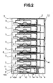
- Fig. 2 is an outlook view of the electronic apparatus shown in Fig. 1, but seen from the right-hand side thereof.
- a plural number of the electronic apparatus units 3 are installed in a manner of multi-stages (in the present embodiment, eight (8) stages, for example, and the details of the electronic apparatus unit will be mentioned about only the unit installed at the lowest stage thereof).
- a CPU 7 i.e., a semiconductor element
- a first cooling system is installed, for circulating a liquid for the purpose of cooling thereof.
- a micro-pump 6, a heat-receiving jacket 15 and also a heat exchanger 8 are connected sequentially, by means of conduits.
- the heat-receiving jacket 15 is thermally connected to the CPU 7, therefore the heat generated from the CPU 7 is absorbed by means of the heat-receiving jacket 15.
- the cooling water absorbing the heat therein is driven to circulate within the direction (i.e., the circulation direction of liquid), as indicted by an arrow 15a, with an aid of the function of the micro-pump 6.
- a large-sized pump 9 is attached on a rear side of the cabinet 2.
- a conduit 12 This conduit is inserted into an inside of the electronic apparatus unit 3 at each stage, and at the same time, a conduit 14 rising up from the large-sized pump 9 in parallel with the cabinet 2 is in contact with an interior wall surface of the cabinet 2.
- Onto the conduit inserted into the inside of the electronic apparatus unit 3 are attached two (2) heat-receiving portions 11 and 12, wherein the heat-receiving portion 10 is thermally connected with the heat-receiving jacket 15 of the first cooling system while the heat-receiving portion 11 is thermally connected with the heat exchanger 8.
- the cooling liquid discharged from the pump 9 circulates in a direction of an arrow 14, and is collected into the large-sized pump, again, after circulating around the electronic apparatus unit 3 installed at each of the stages.
- first and the second cooling systems differ in the circulation direction of the cooling water, as are indicated by the arrows 14 and 15a.
- the heat generated from the CPU 7 in each the electronic apparatus unit 3 is transmitted to the cabinet 2 via the conduit 12, and the heat transmitted up to the cabinet 2 is discharged into an atmosphere, through the natural heat radiation upon the cabinet 2, as a whole, or by means of a cooling fan (not shown in the figure), compulsively, which is provided in the cabinet.
- the first water-cooling system is attached onto each of the electronic apparatus units 3, while also the second water-cooling system is attached onto the cabinet 2, respectively, there is no connection portion of the cooling water between the first water-cooling system and the second water-cooling system. Accordingly, it is possible to eliminate leakage of the cooling water, in particular, when the electronic apparatus unit 3 is attached/detached thereto.
- the circulating direction of the cooling water in the first water-cooling system i.e., the cooling liquid becoming hot due to the heat-generation of the CPU
- the circulating direction of the cooling water in the second water-cooling system which is mounted on the cabinet 2
- they are reversed or opposing to each other; then, the cooling water of the second water-cooling system passes through a high-temperature portion of the electronic apparatus unit 3, and therefore it is possible to mitigate an increase of temperature of the cooling water and also to increase the reliability of the materials of building up the water-cooling system.
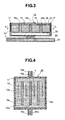
- Fig. 3 is a cross-section view for explaining the structure of the water-cooling jacket 15 described in Fig. 2 mentioned above.
- Fig. 4 is A-A cross-section view of the water-cooling jacket shown in Fig. 3 mentioned above.
- the heat-receiving jacket 15 is thermally connected with the CPU 7 through heat-conductive grease or the like.
- the CPU 7 is mounted on an electronic substrate or board 21.
- the heat-receiving jacket 15 is built up with an upper cover 16 and a lower cover 18, wherein onto the upper cover 16 is fixed the lower cover 18 by means of screws 17, which are inserted from tapped holes formed on the upper cover 16 into tapped holes formed on the lower cover 18.
- Onto the lower cover 18 are formed three (3) pieces of partition walls 18a in one body, and each of tips of the portion wall is closely in contact with an interior wall surface of the upper cover 16. Due to this partition wall 18a, four (4) pieces of flowpassages 19 are formed therewith.
- Areference numeral 18b depicts a supply opening of the cooling water, while 18c a discharge opening of the cooling water.
- the cooling water flows within the four (4) pieces of the flow passages 19, in parallel with, which are defined by the partition walls 18a.
- a reference numeral 20 depicts a liquid sealing portion, within which a very small amount of the cooling water is filled up with.
- This liquid sealing portion 20 carries out the function of so-called a heat pipe.
- the cooling liquid filled within an inside thereof expands due to the heat generated from the CPU 7, thereby spreading within an inside of the liquid sealing portion 20.
- the heat of the CPU 7 spreads out over the entire surface of the liquid sealing portion 20.
- the heat spread is transmits to the cooling liquid within the liquid flow passages 19 of the lower cover 19, and the cooling liquid repeats the following cycle: i.e., being condensed, being liquefied, and turning back to the heat-generation body 7.
- this heat-receiving jacket 15 provided with the liquid sealing portion 20, it is possible to treat with an increase in the density of heat-generation on the heat-generation body 7, thereby enabling cooling down of the heat-generation body 7, with ease.
- the portion where the liquid sealing portion 20 is provided may be made from a plate-like member (i.e., a heat diffusion plate) of a material, being very large in the heat conductivity thereof.
- This heat diffusion plate may be made from a sintered body of carbon, or diamond, for example.
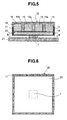
- Fig. 5 is a cress-section view of the water-cooling jacket, according to other embodiment.
- Fig. 6 is B-B cross-section view of the water-cooling jacket shown in Fig. 5 mentioned above.
- an aspect of the present embodiment differing from the embodiment 1 lies in that the liquid flow passages 19 are formed in the upper cover 16.
- the heat-receiving jacket 15 is connected with the CPU, through the heat-conductive grease, etc., thermally.
- the CPU 7 is mounted on the electronic substrate or board 21.
- This heat-receiving jacket 15 is built up with an upper cover 16 and a lower cover 18, wherein onto the upper cover 16 is fixed the lower cover 18 by means of screws 17, which are inserted from tapped holes formed on the upper cover 16 into tapped holes formed on the lower cover 18.
- Onto the lower cover 18 are formed three (3) pieces of partition walls 18a in one body, and each of tips of the portion wall is closely in contact with an interior wall surface of the upper cover 16. Due to this partition wall 18a, four (4) pieces of flow passages 19 are formed with. Since the circulation route of the cooling liquid is completely same to that explained in relation with Fig. 3 mentioned above, therefore explanation thereof will be omitted herein.
- This liquid sealing portion 20 is plate-like in the configuration thereof, and has a hermetically sealed space therein, in which a very small amount of the cooling liquid is filled up with.
- This liquid sealing portion 20 is a means for carry out the function of the heat pile, as was mentioned previously.
- the cooling liquid within inside thereof is expanded due to the heat generated from the CPU 7, thereby spreading the heat within the inside of the liquid sealing portion 20. with this, the heat of the CPU 7 spreads all over the entire surface of the liquid sealing portion 20.
- the heat spreading is transmits to the cooling liquid within the liquid flow passages 19 of the lower cover 19, and the cooling liquid repeats the following cycle: i.e., being condensed, being liquefied, and turning back to the heat-generation body 7.
- this heat-receiving jacket 15 provided with the liquid sealing portion 20, it is possible to treat with the increase in the density of heat-generation of the heat-generation body 7, thereby enabling the cooling down of the heat-generation body 7, with ease.
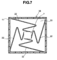
- Fig. 7 is a cross-section view of the liquid sealing portion corresponding to the B-B cross-section view shown in Fig. 5 mentioned above.
- this embodiment is provided for the purpose of further improving or enhancing the heat diffusion, and wherein a zigzagging heat diffusion plate 22 is extended from an outer edge in the vicinity of the heat-generation body 7 located at a central portion of the lower cover 18, up to an outer peripheral wall surface of the lower cover 18.
- a zigzagging heat diffusion plate 22 is extended from an outer edge in the vicinity of the heat-generation body 7 located at a central portion of the lower cover 18, up to an outer peripheral wall surface of the lower cover 18.
- the heat spread is transmitted to the cooling liquid circulating within the housing through the liquid flow passage in the water cooling jacket, therefore it can be radiated into the atmosphere from the portion having a large or wide heat radiation area of the housing. Also, with provision of the heat diffusion plate zigzagging from the vicinity of the center of the water cooling jacket, within the inside of the water-cooling jacket, it is possible to spread the heat generated from the electronic parts further to the water-cooling jacket having a wide area.
- the heat generated from the electronic part can be spread out all over the entire of the cover on the side of the electronic parts through the evaporation heat of the liquid. Further, the heat spread can be radiated into the atmosphere from the portion having a large or wide heat radiation area of the housing.
- the heat diffusion plate zigzagging from a position in the vicinity of the center of the water-cooling jacket within the inside of the liquid sealing portion of the water-cooling jacket, the heat generated from the electronic parts can be further spread out, up to the water-cooling jacket having a wide area.
Landscapes
- Cooling Or The Like Of Electrical Apparatus (AREA)
- Cooling Or The Like Of Semiconductors Or Solid State Devices (AREA)
Applications Claiming Priority (2)
| Application Number | Priority Date | Filing Date | Title |
|---|---|---|---|
| JP2003310850 | 2003-09-03 | ||
| JP2003310850A JP2005079483A (ja) | 2003-09-03 | 2003-09-03 | 電子機器装置 |
Publications (1)
| Publication Number | Publication Date |
|---|---|
| EP1513386A2 true EP1513386A2 (de) | 2005-03-09 |
Family
ID=34131830
Family Applications (1)
| Application Number | Title | Priority Date | Filing Date |
|---|---|---|---|
| EP04005038A Withdrawn EP1513386A2 (de) | 2003-09-03 | 2004-03-03 | Elektronisches Gerät |
Country Status (6)
| Country | Link |
|---|---|
| US (1) | US20050045309A1 (de) |
| EP (1) | EP1513386A2 (de) |
| JP (1) | JP2005079483A (de) |
| KR (1) | KR20050025050A (de) |
| CN (1) | CN1591849A (de) |
| TW (1) | TW200511539A (de) |
Cited By (2)
| Publication number | Priority date | Publication date | Assignee | Title |
|---|---|---|---|---|
| EP2192827A3 (de) * | 2008-11-26 | 2012-02-29 | General Electric Company | Verfahren und Vorrichtung zur Kühlung von Elektronik |
| CN107912002A (zh) * | 2017-12-11 | 2018-04-13 | 湖北理工学院 | 一种防潮通风机电柜 |
Families Citing this family (12)
| Publication number | Priority date | Publication date | Assignee | Title |
|---|---|---|---|---|
| US20050174735A1 (en) * | 2003-08-26 | 2005-08-11 | Nagui Mankaruse | High performance cooling systems |
| JP2007127398A (ja) | 2005-10-05 | 2007-05-24 | Seiko Epson Corp | 熱交換器、熱交換器の製造方法、液冷システム、光源装置、プロジェクタ、電子デバイスユニット、電子機器 |
| JP4876975B2 (ja) * | 2007-03-02 | 2012-02-15 | 株式会社日立製作所 | 電子機器用の冷却装置および受熱部材 |
| US8896335B2 (en) * | 2007-07-30 | 2014-11-25 | Advantest Corporation | Thermal controller for electronic devices |
| KR100917599B1 (ko) * | 2007-12-06 | 2009-09-17 | 한국전자통신연구원 | 평판형 열소산 장치 |
| JPWO2011121819A1 (ja) * | 2010-03-29 | 2013-07-04 | 富士通株式会社 | ループ型ヒートパイプ |
| US9560794B2 (en) | 2011-11-08 | 2017-01-31 | Panasonic Intellectual Property Management Co., Ltd. | Cooling device for cooling rack-type server, and data center provided with same |
| CN102548362A (zh) * | 2011-12-29 | 2012-07-04 | 中兴通讯股份有限公司 | 水冷散热系统 |
| CN105376966A (zh) * | 2014-09-01 | 2016-03-02 | 宜昌迪森智能科技有限公司 | 防尘电器柜 |
| US9883616B2 (en) * | 2014-09-29 | 2018-01-30 | International Business Machines Corporation | Manifold heat exchanger |
| US10085367B2 (en) * | 2015-03-12 | 2018-09-25 | International Business Machines Corporation | Minimizing leakage in liquid cooled electronic equipment |
| CN105824373A (zh) * | 2016-03-22 | 2016-08-03 | 中南林业科技大学 | 一种具有存储器阵列的计算机 |
Family Cites Families (14)
| Publication number | Priority date | Publication date | Assignee | Title |
|---|---|---|---|---|
| US3524497A (en) * | 1968-04-04 | 1970-08-18 | Ibm | Heat transfer in a liquid cooling system |
| US4322737A (en) * | 1979-11-20 | 1982-03-30 | Intel Corporation | Integrated circuit micropackaging |
| US4485429A (en) * | 1982-06-09 | 1984-11-27 | Sperry Corporation | Apparatus for cooling integrated circuit chips |
| US4420035A (en) * | 1982-10-15 | 1983-12-13 | The United States Of America As Represented By The Administrator Of The National Aeronautics And Space Administration | Thermal control system |
| DE69211074T2 (de) * | 1991-08-26 | 1996-10-02 | Sun Microsystems Inc | Verfahren und Apparat zum Kühlen von Mehrchip-Moduln durch die vollständige Wärmerohr-Technologie |
| US5390077A (en) * | 1994-07-14 | 1995-02-14 | At&T Global Information Solutions Company | Integrated circuit cooling device having internal baffle |
| US5529115A (en) * | 1994-07-14 | 1996-06-25 | At&T Global Information Solutions Company | Integrated circuit cooling device having internal cooling conduit |
| US6005772A (en) * | 1997-05-20 | 1999-12-21 | Denso Corporation | Cooling apparatus for high-temperature medium by boiling and condensing refrigerant |
| US6148906A (en) * | 1998-04-15 | 2000-11-21 | Scientech Corporation | Flat plate heat pipe cooling system for electronic equipment enclosure |
| US6052285A (en) * | 1998-10-14 | 2000-04-18 | Sun Microsystems, Inc. | Electronic card with blind mate heat pipes |
| US20030024691A1 (en) * | 2001-07-31 | 2003-02-06 | Leu-Wen Tsay | High efficiency heat sink |
| US6533029B1 (en) * | 2001-09-04 | 2003-03-18 | Thermal Corp. | Non-inverted meniscus loop heat pipe/capillary pumped loop evaporator |
| TW540989U (en) * | 2002-10-04 | 2003-07-01 | Via Tech Inc | Thin planar heat distributor |
| US7019971B2 (en) * | 2003-09-30 | 2006-03-28 | Intel Corporation | Thermal management systems for micro-components |
-
2003
- 2003-09-03 JP JP2003310850A patent/JP2005079483A/ja active Pending
-
2004
- 2004-03-01 TW TW093105301A patent/TW200511539A/zh unknown
- 2004-03-03 EP EP04005038A patent/EP1513386A2/de not_active Withdrawn
- 2004-03-04 KR KR1020040014478A patent/KR20050025050A/ko not_active Ceased
- 2004-03-04 US US10/791,771 patent/US20050045309A1/en not_active Abandoned
- 2004-03-05 CN CNA2004100077692A patent/CN1591849A/zh active Pending
Cited By (2)
| Publication number | Priority date | Publication date | Assignee | Title |
|---|---|---|---|---|
| EP2192827A3 (de) * | 2008-11-26 | 2012-02-29 | General Electric Company | Verfahren und Vorrichtung zur Kühlung von Elektronik |
| CN107912002A (zh) * | 2017-12-11 | 2018-04-13 | 湖北理工学院 | 一种防潮通风机电柜 |
Also Published As
| Publication number | Publication date |
|---|---|
| TW200511539A (en) | 2005-03-16 |
| KR20050025050A (ko) | 2005-03-11 |
| CN1591849A (zh) | 2005-03-09 |
| US20050045309A1 (en) | 2005-03-03 |
| JP2005079483A (ja) | 2005-03-24 |
Similar Documents
| Publication | Publication Date | Title |
|---|---|---|
| US11991856B2 (en) | Liquid submersion cooled electronic systems | |
| EP1513386A2 (de) | Elektronisches Gerät | |
| US20040196628A1 (en) | Electronic apparatus having heat-generating components to be cooled with liquid coolant | |
| US6166907A (en) | CPU cooling system | |
| US7499278B2 (en) | Method and apparatus for dissipating heat from an electronic device | |
| US6131647A (en) | Cooling system for cooling hot object in container | |
| KR20010041932A (ko) | 컴퓨터의 냉각 시스템 | |
| US7457118B1 (en) | Method and apparatus for dispersing heat from high-power electronic devices | |
| US20040042174A1 (en) | Electronic apparatus | |
| US20050178529A1 (en) | Cooling system or electronic apparatus, and electronic apparatus using the same | |
| JP7288998B2 (ja) | 目詰まり防止機構を有するコールドプレート | |
| CN101442894A (zh) | 电子设备 | |
| JP2004047809A (ja) | 発熱素子冷却装置及び電子機器 | |
| US7589962B1 (en) | Apparatus for cooling a heat dissipating device located within a portable computer | |
| US20050183848A1 (en) | Coolant tray of liquid based cooling device | |
| CN113939152B (zh) | 水冷散热模组及电子设备 | |
| EP1708263B1 (de) | Kühlmantel | |
| CN113966159A (zh) | 水冷散热模组、电子设备及电子设备的控制方法 | |
| US20060185826A1 (en) | Liquid cooling system | |
| US12568603B2 (en) | Cooling block assembly for cooling a heat-generating electronic component | |
| JP2010079403A (ja) | 電子装置用冷却システム | |
| JP2004194401A (ja) | 盤用冷却装置 | |
| KR101172679B1 (ko) | 공기조화기의 실외기 | |
| KR20040061286A (ko) | Tec와 히트 파이프 조합의 하이브리드 히트 익스체인저 | |
| RU75020U1 (ru) | Устройство для охлаждения тепловыделяющей аппаратуры |
Legal Events
| Date | Code | Title | Description |
|---|---|---|---|
| PUAI | Public reference made under article 153(3) epc to a published international application that has entered the european phase |
Free format text: ORIGINAL CODE: 0009012 |
|
| AK | Designated contracting states |
Kind code of ref document: A2 Designated state(s): AT BE BG CH CY CZ DE DK EE ES FI FR GB GR HU IE IT LI LU MC NL PL PT RO SE SI SK TR |
|
| AX | Request for extension of the european patent |
Extension state: AL LT LV MK |
|
| STAA | Information on the status of an ep patent application or granted ep patent |
Free format text: STATUS: THE APPLICATION IS DEEMED TO BE WITHDRAWN |
|
| 18D | Application deemed to be withdrawn |
Effective date: 20061003 |