EP0169550A2 - Wärmetransportvorrichtung - Google Patents
Wärmetransportvorrichtung Download PDFInfo
- Publication number
- EP0169550A2 EP0169550A2 EP85109228A EP85109228A EP0169550A2 EP 0169550 A2 EP0169550 A2 EP 0169550A2 EP 85109228 A EP85109228 A EP 85109228A EP 85109228 A EP85109228 A EP 85109228A EP 0169550 A2 EP0169550 A2 EP 0169550A2
- Authority
- EP
- European Patent Office
- Prior art keywords
- working fluid
- bubble
- check valve
- pipe means
- heating block
- Prior art date
- Legal status (The legal status is an assumption and is not a legal conclusion. Google has not performed a legal analysis and makes no representation as to the accuracy of the status listed.)
- Granted
Links
Images

Classifications
-
- F—MECHANICAL ENGINEERING; LIGHTING; HEATING; WEAPONS; BLASTING
- F28—HEAT EXCHANGE IN GENERAL
- F28D—HEAT-EXCHANGE APPARATUS, NOT PROVIDED FOR IN ANOTHER SUBCLASS, IN WHICH THE HEAT-EXCHANGE MEDIA DO NOT COME INTO DIRECT CONTACT
- F28D15/00—Heat-exchange apparatus with the intermediate heat-transfer medium in closed tubes passing into or through the conduit walls ; Heat-exchange apparatus employing intermediate heat-transfer medium or bodies
- F28D15/02—Heat-exchange apparatus with the intermediate heat-transfer medium in closed tubes passing into or through the conduit walls ; Heat-exchange apparatus employing intermediate heat-transfer medium or bodies in which the medium condenses and evaporates, e.g. heat pipes
- F28D15/0266—Heat-exchange apparatus with the intermediate heat-transfer medium in closed tubes passing into or through the conduit walls ; Heat-exchange apparatus employing intermediate heat-transfer medium or bodies in which the medium condenses and evaporates, e.g. heat pipes with separate evaporating and condensing chambers connected by at least one conduit; Loop-type heat pipes; with multiple or common evaporating or condensing chambers
-
- F—MECHANICAL ENGINEERING; LIGHTING; HEATING; WEAPONS; BLASTING
- F24—HEATING; RANGES; VENTILATING
- F24D—DOMESTIC- OR SPACE-HEATING SYSTEMS, e.g. CENTRAL HEATING SYSTEMS; DOMESTIC HOT-WATER SUPPLY SYSTEMS; ELEMENTS OR COMPONENTS THEREFOR
- F24D3/00—Hot-water central heating systems
Definitions
- This invention relates to a heat transport apparatus which is capable of transporting heat from a heat absorption section to a heat release section without using any external mechanical drive only by heating and simultaneously circulating a liquid.
- heat pipes, heat siphons, etc. have been well known as heat transport apparatus.
- these known apparatus cannot be used for long-distance heat transportation or for transporting heat downward against the force of gravity, since they utilize capillary attraction or gravity.
- a loop-type heat transport element has been developed in order to eliminate these faults.
- two loop-shaped heating tubes are required at the heating section, and the heating section has to be positioned above the cooling section and also below the bends of tubes for connection between the heating and cooling sections.
- the two heating tubes should be somewhat inclined.
- the loop-type heat transport element is of complicated structure, has several limitations or manner of installation and cannot be used in a portable form except so that it is limited to application in a fixed installation such as a chemical plant.
- An object of the invention is to provide a heat transport apparatus capable of transporting heat from a heat absorption section to a heat release section without any adverse influence from gravity or need for any external mechanical drive.
- the heat transport apparatus comprises a heating block made of material having a high heat conductivity and having a conical recess formed therein to produce a small bubble, pipe means made of material having a low heat conductivity, the heating block being positioned in the pipe means and arranged to be heated for growing of the bubble, flapper-type check valves provided at the ends of the pipe means, the growing bubble increasing the pressure of a working fluid in the pipe means, the increased pressure causing one check valve to open and the other check valve to close, thereby displacing the working fluid through the opened check valve under the action of the grown bubble, further pipe means connected between an inlet opening of one of the check valves and an outlet opening of the other check valve for circulating the working fluid to pass it through the other check valve into the heating block when the bubble is constricted, and a radiator positioned in the further pipe means for radiating heat from the working fluid.
- an accumulator may be positioned in the further pipe means.
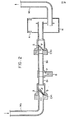
- a heat transport apparatus comprises a heating block B having a conical recess P formed therein and connected between pipes G 1 and G 2 .
- the heating block B is made of any suitable material having a high heat conductivity while pipes G l and G 2 are of a material having a low heat conductivity.
- a check valve CV 1 is provided at the inlet end of the pipe G l and a check valve CV 2 is provided at the outlet end of the pipe G 2 , which is connected to the inlet opening of an accumulator H having bellows A formed from any suitable flexible material.
- a pipe M 1 extends from the outlet opening of the accumulator H to the inlet opening of a radiator EX which is connected at its outlet opening to the check valve CV 1 by means of a pipe M 2 .
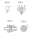
- Each of the check valves CV 1 and CV 2 includes a flapper F formed from a sheet of rubber or metal foil, and an inclined seat T having sealing O-ring S positioned therein and cooperating with the flapper F.
- flapper F is provided with leaf spring F' formed integrally therewith to provide a weak force with which the flapper is urged into contact with the sealing ring S on the seat T when fixed at its end to the check valve.
- the heating block may be provided with a cavity R formed therein at the apex of the conical recess P as shown in Figure 4.
- Figures 5 and 6 show a circular flapper F positioned perpendicular to the flow of the working fluid and movably retained in a retainer D.
- Pipes M l and M 2 may be of metal or of a flexible plastic such as vinyl chloride.
- the radiator EX may comprise a tube made of any suitable material having a high heat conductivity and fins of the same material positioned around the tube.
- the working fluid is preferably water, but any suitable cooling medium (R-ll, R-12, ammonia or the like) may be used as the working fluid.
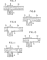
- the closed circuit of the heat transport apparatus is filled with the working fluid, but since the angle of the cone of the recess P in the heating block B is smaller than the angle of contact between the material of the heating block and the working fluid, the conical recess P is not completely filled with the working fluid so that a bubble seed N is left at the apex thereof (see Figure 7).
- the working fluid covering the -bubble seed N is heated in the conical recess P by heating the heating block B from its outside by any suitable heat source. As the temperature of the heated working fluid exceeds the saturation temperature of the working fluid vapor at the internal pressure in the bubble seed N, the working fluid evaporates towards the bubble at the interface between the working fluid and the bubble so that the bubble N can begin to grow (see Figure 8).
- the amount of vapor pressure or superheating required to grow a bubble of identical volume is smaller in the case of a large conical recess than in the case where a small bubble seed is grown on a flat surface. This is because in case of the larger conical recess, the radius of curvature at the interface between the bubble and the working fluid is longer than that in case of the flat surface, and the surface tension on the interface which tends to constrict the bubble, is inversely proportional to the radius of curvature.
- the continuously growing bubble increases the pressure of the working fluid in the pipes G 1 and G 2 , whereby the check valve CV 1 is closed and the check valve CV 2 is opened.
- the working fluid in the pipe G 2 is displaced out through the open check valve CV 2 into the accumulator H by the continuously growing bubble N.
- the surface area of the bubble increases as it grows on the side of the pipe G 2 but growth of the bubble stops when the amount of evaporation of the working fluid at the heating block becomes identical with the amount of condensation of vapor on the increased surface area of the bubble ( Figure 9).
- the working fluid in the pipes G 1 and G 2 is heated mainly by the heat given off by condensation of the vapor.
- the heating block B is cooled by the working fluid flowing thereinto to further constrict the bubble, thereby creating a negative pressure with which the working fluid is drawn from the accumulator through the radiator EX and then, through the heating block B into the pipe G 2 .
- the bubble momentarily disappears.
- a fresh bubble seed N is forms at the apex of the conical recess P of the heating block B (see Figures 10 and 11).
- the working fluid is intermittently circulated in the closed circuit due to pressure differential created by the growth and constriction of the vapor bubble. Therefore, operation of the heat transport apparatus can be carried out in any attitudes without beding disturbed by the force of gravity. It therefore can be applied to portable equipment. Only slight heating is required to heat the heating block for growth of the bubble. Since the check valve is in the form of a flapper valve which can sensitively respond to extremely small pressure differentials, dry-out does not occur even when only a slight amount of heat is supplied to the heating block. The amount of the circulating working fluid increases in proportion to the amount of heat, and dry-out does not occur even when the temperature of the working fluid flowing through the check valve CV 1 into the heating block considerably increases.
- the accumulator H serves to trap non-condensable gases contained in the working fluid, by the difference in density, thereby preventing the non-condensable gases from circulating in the closed circuit. If the pipes M 1 and M 2 are formed from flexible material, no accumulator is required because the flexible pipes function as an accumulator.
Landscapes
- Engineering & Computer Science (AREA)
- General Engineering & Computer Science (AREA)
- Thermal Sciences (AREA)
- Mechanical Engineering (AREA)
- Physics & Mathematics (AREA)
- Chemical & Material Sciences (AREA)
- Combustion & Propulsion (AREA)
- Life Sciences & Earth Sciences (AREA)
- Sustainable Development (AREA)
- Reciprocating Pumps (AREA)
- Central Heating Systems (AREA)
- Details Of Valves (AREA)
- Electromagnetic Pumps, Or The Like (AREA)
Applications Claiming Priority (2)
| Application Number | Priority Date | Filing Date | Title |
|---|---|---|---|
| JP153442/84 | 1984-07-24 | ||
| JP15344284A JPS6131884A (ja) | 1984-07-24 | 1984-07-24 | 熱伝達装置 |
Publications (3)
| Publication Number | Publication Date |
|---|---|
| EP0169550A2 true EP0169550A2 (de) | 1986-01-29 |
| EP0169550A3 EP0169550A3 (en) | 1987-12-23 |
| EP0169550B1 EP0169550B1 (de) | 1990-12-19 |
Family
ID=15562626
Family Applications (1)
| Application Number | Title | Priority Date | Filing Date |
|---|---|---|---|
| EP85109228A Expired EP0169550B1 (de) | 1984-07-24 | 1985-07-23 | Wärmetransportvorrichtung |
Country Status (4)
| Country | Link |
|---|---|
| US (1) | US4625790A (de) |
| EP (1) | EP0169550B1 (de) |
| JP (1) | JPS6131884A (de) |
| DE (1) | DE3580945D1 (de) |
Cited By (1)
| Publication number | Priority date | Publication date | Assignee | Title |
|---|---|---|---|---|
| EP0321945B1 (de) * | 1987-12-22 | 1994-08-17 | Kenji Okayasu | Wärmeleitende Vorrichtung |
Families Citing this family (21)
| Publication number | Priority date | Publication date | Assignee | Title |
|---|---|---|---|---|
| JPH0718408B2 (ja) * | 1986-06-23 | 1995-03-06 | 謙治 岡安 | 熱駆動ポンプ |
| JPH063354B2 (ja) * | 1987-06-23 | 1994-01-12 | アクトロニクス株式会社 | ル−プ型細管ヒ−トパイプ |
| US4841943A (en) * | 1987-08-06 | 1989-06-27 | Favreau Danny W | Gasoline superheater |
| JP2519959B2 (ja) * | 1987-12-22 | 1996-07-31 | 謙治 岡安 | 電子機器冷却装置 |
| JP2657809B2 (ja) * | 1987-12-22 | 1997-09-30 | 謙治 岡安 | 熱伝達装置 |
| JP2859927B2 (ja) * | 1990-05-16 | 1999-02-24 | 株式会社東芝 | 冷却装置および温度制御装置 |
| JPH04126924A (ja) * | 1990-09-19 | 1992-04-27 | Takenaka Komuten Co Ltd | 給湯システム |
| JP3088127B2 (ja) * | 1991-05-22 | 2000-09-18 | 謙治 岡安 | 携帯式熱伝達装置 |
| US5394936A (en) * | 1993-03-12 | 1995-03-07 | Intel Corporation | High efficiency heat removal system for electric devices and the like |
| JPH07111312B2 (ja) * | 1993-12-17 | 1995-11-29 | 工業技術院長 | 熱伝達装置 |
| US6283718B1 (en) * | 1999-01-28 | 2001-09-04 | John Hopkins University | Bubble based micropump |
| JP3964580B2 (ja) * | 1999-09-03 | 2007-08-22 | 富士通株式会社 | 冷却ユニット |
| US6820683B1 (en) * | 2000-01-04 | 2004-11-23 | Li Jia Hao | Bubble cycling heat exchanger |
| US6789611B1 (en) | 2000-01-04 | 2004-09-14 | Jia Hao Li | Bubble cycling heat exchanger |
| US6856037B2 (en) * | 2001-11-26 | 2005-02-15 | Sony Corporation | Method and apparatus for converting dissipated heat to work energy |
| JP3860055B2 (ja) * | 2002-03-14 | 2006-12-20 | 三菱電機株式会社 | 薄型ループ状流路デバイスおよびそれを用いた温度制御機器 |
| US20080186801A1 (en) * | 2007-02-06 | 2008-08-07 | Qisda Corporation | Bubble micro-pump and two-way fluid-driving device, particle-sorting device, fluid-mixing device, ring-shaped fluid-mixing device and compound-type fluid-mixing device using the same |
| JP5676205B2 (ja) * | 2010-10-26 | 2015-02-25 | 株式会社 正和 | ループ型ヒートパイプおよびその製造方法 |
| EP2735834A4 (de) * | 2011-07-21 | 2014-12-10 | Panasonic Corp | Kühlvorrichtung, elektronische vorrichtung damit und elektrofahrzeug |
| JP5252059B2 (ja) * | 2011-10-11 | 2013-07-31 | パナソニック株式会社 | 冷却装置 |
| TWI688326B (zh) * | 2018-01-17 | 2020-03-11 | 緯創資通股份有限公司 | 冷卻液補充機構及具有冷卻液補充機構的冷卻循環系統及電子設備 |
Family Cites Families (9)
| Publication number | Priority date | Publication date | Assignee | Title |
|---|---|---|---|---|
| GB897785A (en) * | 1959-07-29 | 1962-05-30 | Lucien Grillet | Improvements in or relating to space heating systems |
| US3392781A (en) * | 1964-09-29 | 1968-07-16 | Gen Electric | Vaporizing heat transfer device |
| US3929305A (en) * | 1972-10-27 | 1975-12-30 | Nasa | Heat exchanger system and method |
| GB1558551A (en) * | 1977-02-23 | 1980-01-03 | Org Europeene De Rech | Pressure pump heat transfer system |
| US4120172A (en) * | 1977-05-05 | 1978-10-17 | The United States Of America As Represented By The United States Department Of Energy | Heat transport system |
| US4212593A (en) * | 1979-01-25 | 1980-07-15 | Utah State University Foundation | Heat-powered water pump |
| JPS56158783U (de) * | 1980-04-29 | 1981-11-26 | ||
| GB2081435A (en) * | 1980-08-07 | 1982-02-17 | Euratom | Device for passive downwards heat transport and integrated solar collectur incorporating same |
| JPS5787235U (de) * | 1980-10-15 | 1982-05-29 |
-
1984
- 1984-07-24 JP JP15344284A patent/JPS6131884A/ja active Granted
-
1985
- 1985-07-22 US US06/757,605 patent/US4625790A/en not_active Expired - Lifetime
- 1985-07-23 DE DE8585109228T patent/DE3580945D1/de not_active Expired - Lifetime
- 1985-07-23 EP EP85109228A patent/EP0169550B1/de not_active Expired
Cited By (1)
| Publication number | Priority date | Publication date | Assignee | Title |
|---|---|---|---|---|
| EP0321945B1 (de) * | 1987-12-22 | 1994-08-17 | Kenji Okayasu | Wärmeleitende Vorrichtung |
Also Published As
| Publication number | Publication date |
|---|---|
| JPS6131884A (ja) | 1986-02-14 |
| US4625790A (en) | 1986-12-02 |
| EP0169550A3 (en) | 1987-12-23 |
| JPH0467112B2 (de) | 1992-10-27 |
| DE3580945D1 (de) | 1991-01-31 |
| EP0169550B1 (de) | 1990-12-19 |
Similar Documents
| Publication | Publication Date | Title |
|---|---|---|
| US4625790A (en) | Heat transport apparatus | |
| US4792283A (en) | Heat-driven pump | |
| US4574875A (en) | Heat exchanger for geothermal heating and cooling systems | |
| JP2859927B2 (ja) | 冷却装置および温度制御装置 | |
| US4044797A (en) | Heat transfer pipe | |
| US10619939B2 (en) | Intermittent thermosyphon | |
| CN101660880B (zh) | 传导率可变热管 | |
| CN105074373A (zh) | 具有两相流体的热传输装置 | |
| JPH01167594A (ja) | 熱伝達装置 | |
| JPH04190883A (ja) | 温海水から淡水を採取する方法及び装置 | |
| US4333312A (en) | Thermodynamic energy conversion system and method, utilizing a thermodynamic working fluid of encased expandites | |
| US20070151703A1 (en) | Grid and yarn membrane heat pipes | |
| RU2213912C2 (ru) | Солнечный энергетический комплекс | |
| US5660618A (en) | Gas-liquid separating apparatus for a gas boiler | |
| JPH0461195B2 (de) | ||
| US4880503A (en) | Hydraulic reservoir | |
| CN208398693U (zh) | 微通道阵列辅助驱动的回路热管 | |
| CN214662400U (zh) | 一种实验室给水用双密封排气装置 | |
| US2617759A (en) | Salt water evaporator | |
| JP2535960Y2 (ja) | 活魚用水槽装置 | |
| JPH02287068A (ja) | 抽気装置 | |
| JPS6414597A (en) | Heat exchanging device | |
| JP2001207493A (ja) | 凍結防止配管構造 | |
| JP2005121065A (ja) | 液体圧送装置 | |
| US813606A (en) | Air-valve. |
Legal Events
| Date | Code | Title | Description |
|---|---|---|---|
| PUAI | Public reference made under article 153(3) epc to a published international application that has entered the european phase |
Free format text: ORIGINAL CODE: 0009012 |
|
| AK | Designated contracting states |
Designated state(s): DE FR GB |
|
| PUAL | Search report despatched |
Free format text: ORIGINAL CODE: 0009013 |
|
| AK | Designated contracting states |
Kind code of ref document: A3 Designated state(s): DE FR GB |
|
| 17P | Request for examination filed |
Effective date: 19880304 |
|
| 17Q | First examination report despatched |
Effective date: 19890118 |
|
| GRAA | (expected) grant |
Free format text: ORIGINAL CODE: 0009210 |
|
| AK | Designated contracting states |
Kind code of ref document: B1 Designated state(s): DE FR GB |
|
| ET | Fr: translation filed | ||
| REF | Corresponds to: |
Ref document number: 3580945 Country of ref document: DE Date of ref document: 19910131 |
|
| PLBE | No opposition filed within time limit |
Free format text: ORIGINAL CODE: 0009261 |
|
| STAA | Information on the status of an ep patent application or granted ep patent |
Free format text: STATUS: NO OPPOSITION FILED WITHIN TIME LIMIT |
|
| 26N | No opposition filed | ||
| REG | Reference to a national code |
Ref country code: GB Ref legal event code: IF02 |
|
| PGFP | Annual fee paid to national office [announced via postgrant information from national office to epo] |
Ref country code: FR Payment date: 20030523 Year of fee payment: 19 |
|
| PGFP | Annual fee paid to national office [announced via postgrant information from national office to epo] |
Ref country code: DE Payment date: 20030711 Year of fee payment: 19 |
|
| PGFP | Annual fee paid to national office [announced via postgrant information from national office to epo] |
Ref country code: GB Payment date: 20030723 Year of fee payment: 19 |
|
| PG25 | Lapsed in a contracting state [announced via postgrant information from national office to epo] |
Ref country code: GB Free format text: LAPSE BECAUSE OF NON-PAYMENT OF DUE FEES Effective date: 20040723 |
|
| PG25 | Lapsed in a contracting state [announced via postgrant information from national office to epo] |
Ref country code: DE Free format text: LAPSE BECAUSE OF NON-PAYMENT OF DUE FEES Effective date: 20050201 |
|
| GBPC | Gb: european patent ceased through non-payment of renewal fee |
Effective date: 20040723 |
|
| PG25 | Lapsed in a contracting state [announced via postgrant information from national office to epo] |
Ref country code: FR Free format text: LAPSE BECAUSE OF NON-PAYMENT OF DUE FEES Effective date: 20050331 |
|
| REG | Reference to a national code |
Ref country code: FR Ref legal event code: ST |