EP0321898B1 - Schutzvorrichtung für eine Kesselwand mit Wärmerückgewinnung und Verfahren zur Herstellung dieser Vorrichtung - Google Patents
Schutzvorrichtung für eine Kesselwand mit Wärmerückgewinnung und Verfahren zur Herstellung dieser Vorrichtung Download PDFInfo
- Publication number
- EP0321898B1 EP0321898B1 EP88121208A EP88121208A EP0321898B1 EP 0321898 B1 EP0321898 B1 EP 0321898B1 EP 88121208 A EP88121208 A EP 88121208A EP 88121208 A EP88121208 A EP 88121208A EP 0321898 B1 EP0321898 B1 EP 0321898B1
- Authority
- EP
- European Patent Office
- Prior art keywords
- bricks
- fins
- windows
- fireproof
- screen
- Prior art date
- Legal status (The legal status is an assumption and is not a legal conclusion. Google has not performed a legal analysis and makes no representation as to the accuracy of the status listed.)
- Expired - Lifetime
Links
Images
Classifications
-
- F—MECHANICAL ENGINEERING; LIGHTING; HEATING; WEAPONS; BLASTING
- F23—COMBUSTION APPARATUS; COMBUSTION PROCESSES
- F23M—CASINGS, LININGS, WALLS OR DOORS SPECIALLY ADAPTED FOR COMBUSTION CHAMBERS, e.g. FIREBRIDGES; DEVICES FOR DEFLECTING AIR, FLAMES OR COMBUSTION PRODUCTS IN COMBUSTION CHAMBERS; SAFETY ARRANGEMENTS SPECIALLY ADAPTED FOR COMBUSTION APPARATUS; DETAILS OF COMBUSTION CHAMBERS, NOT OTHERWISE PROVIDED FOR
- F23M5/00—Casings; Linings; Walls
- F23M5/08—Cooling thereof; Tube walls
-
- F—MECHANICAL ENGINEERING; LIGHTING; HEATING; WEAPONS; BLASTING
- F22—STEAM GENERATION
- F22B—METHODS OF STEAM GENERATION; STEAM BOILERS
- F22B37/00—Component parts or details of steam boilers
- F22B37/02—Component parts or details of steam boilers applicable to more than one kind or type of steam boiler
- F22B37/10—Water tubes; Accessories therefor
- F22B37/107—Protection of water tubes
- F22B37/108—Protection of water tube walls
-
- F—MECHANICAL ENGINEERING; LIGHTING; HEATING; WEAPONS; BLASTING
- F23—COMBUSTION APPARATUS; COMBUSTION PROCESSES
- F23M—CASINGS, LININGS, WALLS OR DOORS SPECIALLY ADAPTED FOR COMBUSTION CHAMBERS, e.g. FIREBRIDGES; DEVICES FOR DEFLECTING AIR, FLAMES OR COMBUSTION PRODUCTS IN COMBUSTION CHAMBERS; SAFETY ARRANGEMENTS SPECIALLY ADAPTED FOR COMBUSTION APPARATUS; DETAILS OF COMBUSTION CHAMBERS, NOT OTHERWISE PROVIDED FOR
- F23M5/00—Casings; Linings; Walls
- F23M5/04—Supports for linings
-
- Y—GENERAL TAGGING OF NEW TECHNOLOGICAL DEVELOPMENTS; GENERAL TAGGING OF CROSS-SECTIONAL TECHNOLOGIES SPANNING OVER SEVERAL SECTIONS OF THE IPC; TECHNICAL SUBJECTS COVERED BY FORMER USPC CROSS-REFERENCE ART COLLECTIONS [XRACs] AND DIGESTS
- Y10—TECHNICAL SUBJECTS COVERED BY FORMER USPC
- Y10S—TECHNICAL SUBJECTS COVERED BY FORMER USPC CROSS-REFERENCE ART COLLECTIONS [XRACs] AND DIGESTS
- Y10S122/00—Liquid heaters and vaporizers
- Y10S122/13—Tubes - composition and protection
-
- Y—GENERAL TAGGING OF NEW TECHNOLOGICAL DEVELOPMENTS; GENERAL TAGGING OF CROSS-SECTIONAL TECHNOLOGIES SPANNING OVER SEVERAL SECTIONS OF THE IPC; TECHNICAL SUBJECTS COVERED BY FORMER USPC CROSS-REFERENCE ART COLLECTIONS [XRACs] AND DIGESTS
- Y10—TECHNICAL SUBJECTS COVERED BY FORMER USPC
- Y10T—TECHNICAL SUBJECTS COVERED BY FORMER US CLASSIFICATION
- Y10T29/00—Metal working
- Y10T29/49—Method of mechanical manufacture
- Y10T29/4935—Heat exchanger or boiler making
- Y10T29/49357—Regenerator or recuperator making
Definitions
- the present invention relates to a device for protecting, thanks to refractory bricks, the screen of a heat recovery boiler, in particular for waste incineration furnaces, said refractory bricks being attached to said screen formed by vertical tubes joined by fins. of welded jointing, the intervals remaining between the bricks and the screen being filled with refractory cement.
- Such a device is known from document FR-A-2 611 864.
- the tubes are provided with auxiliary fins periodically interrupted on which the refractory bricks provided with notches are hung, said notches being interrupted for the bricks fixed to the level of interruption of the corresponding fins and uninterrupted for the others.
- each tube is provided, in addition to the junction fins, fins intended for the attachment of bricks, and that one obtains bricks of two different types.
- the object of the present invention is to provide a device for protecting boiler screens which does not require welding on each tube of fins for attaching bricks, and which only uses one type of refractory brick.
- the device according to the invention is characterized in that the screen has windows pierced in the securing fins, in that the bricks are each provided with at least one pin latching pin forming an angle with the horizontal and such that each brick is kept suspended by its weight in the window (s) of the corresponding screen.
- the invention also relates to a manufacturing method characterized in that one welds between the vertical tubes of the longitudinal fins, in that one cuts in these fins windows at regular vertical spacings, corresponding to the height of the refractory bricks , in that a layer of refractory cement is applied to the surface of the tubes and fins intended to receive the refractory bricks, and what is hung in the windows each of the bricks by its hooking stud.
- the device comprises metal boxes filled with refractory cement, welded between the vertical tubes of the longitudinal fins, windows are cut from these fins with regular vertical spacings, corresponding to the height of the refractory bricks, applied to the rear face fins around the windows, a housing, and welds this housing on this rear face, the housing is filled with refractory cement, a layer of refractory cement is applied to the surface of the tubes and fins intended to receive the refractory bricks, and we hang in the windows each of the bricks by its hooking stud.
- the windows are cut out in the fins by automatic punching.
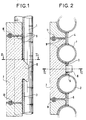
- the tubes 1 and 2 and the adjacent tubes are joined by fins such as 3, 4, 5, to form a screen.
- the fin 3 arranged between the tubes 1 and 2 is pierced at regular vertical intervals with windows for hanging refractory bricks, for example with silicon carbide.
- a single window 6 and the corresponding refractory brick 7 have been shown.
- the refractory brick 7 is provided with a hooking stud 8 with an axis inclined on the horizontal, for example at 45 °, and directed downwards.
- the window is of substantially rectangular shape and the cross section of the attachment stud is also rectangular, and of height and width slightly less than the height and the width of the window.
- a refractory cement 9 is placed in the gaps remaining between the refractory bricks and between these and the metal screen, in particular in the window around the periphery of the attachment stud.
- horizontal rods such as 10 and vertical rods such as 11 ensure good securing of the adjacent bricks vertically and horizontally.
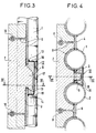
- the device of Figures 3 and 4 is similar to that of Figures 1 and 2, but it further comprises a metal box 12 welded to the junction fin by welding seams 13 above the window and 14 below of it.
- This box has a rear panel 17, an upper panel 16 and a lower panel 18. It is applied laterally against the periphery of the tubes 1 and 2, and thus constitutes a cavity which is filled with refractory cement around the nipple d anchor 8 of the corresponding brick.
- windows are formed at regular vertical intervals, corresponding to the height of the refractory bricks, windows by automatic punching.
- a layer of refractory cement of a few centimeters on the surface of the fins and tubes, then hang the bricks in the windows with their stud attachment, also after having provided the side faces of the bricks facing each other with a layer of refractory cement.
- the connecting rods made of refractory material 10, 11 are introduced into the vertical and horizontal channels of the lateral, upper and lower faces of the bricks.
- the protection device comprises a box filled with refractory cement drowning the nipple for hanging the brick (FIGS. 3 and 4)
- the box 12 is placed behind the window.
- the upper and lower sides of the box are welded to the fin with weld beads, the cavity thus formed is filled with refractory cement, then the layer of refractory cement is applied to the tubes and the fins.
- the side faces of the facing bricks are also provided with a layer of refractory cement, and the rods for fastening the adjacent bricks are introduced into the horizontal and vertical channels of the bricks.
Landscapes
- Engineering & Computer Science (AREA)
- Mechanical Engineering (AREA)
- General Engineering & Computer Science (AREA)
- Chemical & Material Sciences (AREA)
- Combustion & Propulsion (AREA)
- Thermal Sciences (AREA)
- Physics & Mathematics (AREA)
- Furnace Housings, Linings, Walls, And Ceilings (AREA)
- Waste-Gas Treatment And Other Accessory Devices For Furnaces (AREA)
- Buildings Adapted To Withstand Abnormal External Influences (AREA)
- Control Of Combustion (AREA)
- Formation Of Various Coating Films On Cathode Ray Tubes And Lamps (AREA)
- Control Of Steam Boilers And Waste-Gas Boilers (AREA)
- Processing And Handling Of Plastics And Other Materials For Molding In General (AREA)
- Heating, Cooling, Or Curing Plastics Or The Like In General (AREA)
Claims (6)
Priority Applications (1)
| Application Number | Priority Date | Filing Date | Title |
|---|---|---|---|
| AT88121208T ATE64450T1 (de) | 1987-12-22 | 1988-12-19 | Schutzvorrichtung fuer eine kesselwand mit waermerueckgewinnung und verfahren zur herstellung dieser vorrichtung. |
Applications Claiming Priority (2)
| Application Number | Priority Date | Filing Date | Title |
|---|---|---|---|
| FR8717918 | 1987-12-22 | ||
| FR8717918A FR2624952B1 (fr) | 1987-12-22 | 1987-12-22 | Dispositif de protection d'un ecran de chaudiere de recuperation de chaleur et procede de fabrication de ce dispositif |
Publications (2)
| Publication Number | Publication Date |
|---|---|
| EP0321898A1 EP0321898A1 (de) | 1989-06-28 |
| EP0321898B1 true EP0321898B1 (de) | 1991-06-12 |
Family
ID=9358154
Family Applications (1)
| Application Number | Title | Priority Date | Filing Date |
|---|---|---|---|
| EP88121208A Expired - Lifetime EP0321898B1 (de) | 1987-12-22 | 1988-12-19 | Schutzvorrichtung für eine Kesselwand mit Wärmerückgewinnung und Verfahren zur Herstellung dieser Vorrichtung |
Country Status (9)
| Country | Link |
|---|---|
| US (1) | US4934322A (de) |
| EP (1) | EP0321898B1 (de) |
| JP (1) | JPH0697081B2 (de) |
| AT (1) | ATE64450T1 (de) |
| AU (1) | AU607376B2 (de) |
| BR (1) | BR8806777A (de) |
| DE (1) | DE3863284D1 (de) |
| ES (1) | ES2022584B3 (de) |
| FR (1) | FR2624952B1 (de) |
Families Citing this family (12)
| Publication number | Priority date | Publication date | Assignee | Title |
|---|---|---|---|---|
| FR2611864B1 (fr) * | 1987-02-27 | 1989-05-05 | Stein Industrie | Dispositif de protection d'ecrans de chaudieres, notamment pour fours d'incineration d'ordures, et procede de fabrication de ce dispositif |
| DE4226284A1 (de) * | 1992-08-08 | 1994-02-10 | Babcock Sonderbau Gmbh | Verkleidung einer Rohrwand |
| US5423294A (en) * | 1993-12-03 | 1995-06-13 | Wheelabrator Environmental Systems, Inc. | Furnace tile and expansion joint |
| US5542378A (en) * | 1994-06-02 | 1996-08-06 | Saint-Gobain/Norton Industrial Ceramics Corp. | Waterwall tube block design |
| US5511609A (en) * | 1995-01-12 | 1996-04-30 | Tyler; John T. | Tube shield with tongue and locking block assembly |
| FR2747338B1 (fr) * | 1996-04-10 | 1998-05-22 | Pasek France | Dispositif de pressage pour la pose des pieces refractaires |
| EP0854321A4 (de) * | 1996-08-07 | 2001-12-19 | Mitsubishi Heavy Ind Ltd | Feuerfeste schutzstruktur für wasserrohre |
| DE59903399D1 (de) * | 1998-03-19 | 2002-12-19 | Siemens Ag | Wandsegment für einen brennraum sowie brennraum |
| FR2785670B1 (fr) * | 1998-11-10 | 2001-01-05 | Mediterranee Const Ind | Dispositif de protection contre la corrosion et/ou l'abrasion d'un panneau de tubes notamment d'un surchauffeur d'une chaudiere et procede de fixation de coquilles de protection a au moins une paroi d'un tel panneau |
| DE102004063813A1 (de) * | 2004-12-30 | 2006-07-13 | Saint-Gobain Industriekeramik Düsseldorf Gmbh | Hitzeschutzkörper für ein Schutzsystem für eine Ofeninnenwand |
| US8522729B2 (en) * | 2008-07-18 | 2013-09-03 | Babcock & Wilcox Power Generation Group, Inc. | Contoured flat stud and stud arrangement for cyclone slag taps |
| WO2021226332A1 (en) * | 2020-05-07 | 2021-11-11 | Zampell Refractories, Inc. | Tile assembly for a waterwall panel |
Family Cites Families (6)
| Publication number | Priority date | Publication date | Assignee | Title |
|---|---|---|---|---|
| GB409827A (en) * | 1932-12-22 | 1934-05-10 | Bernitz Furnace Appliance Comp | Improvements in and relating to furnace walls and blocks therefor |
| US2368265A (en) * | 1940-07-27 | 1945-01-30 | Babcock & Wilcox Co | Furnace wall |
| DE1952140A1 (de) * | 1969-10-16 | 1971-04-29 | Steinmueller Gmbh L & C | Dampferzeugerwandelemente mit Einruestvorrichtungen |
| FR2592145B1 (fr) * | 1985-12-23 | 1989-08-18 | Cometherm Sa Cie Expl Thermiqu | Procede de realisation de parois refractaires de protection de fours ou chambres de combustion et brique refractaire pour la mise en oeuvre dudit procede. |
| GB2201236B (en) * | 1987-02-18 | 1990-10-17 | W B Black & Sons | Improvements in refractory lined bodies |
| FR2611864B1 (fr) * | 1987-02-27 | 1989-05-05 | Stein Industrie | Dispositif de protection d'ecrans de chaudieres, notamment pour fours d'incineration d'ordures, et procede de fabrication de ce dispositif |
-
1987
- 1987-12-22 FR FR8717918A patent/FR2624952B1/fr not_active Expired - Fee Related
-
1988
- 1988-12-19 DE DE8888121208T patent/DE3863284D1/de not_active Expired - Fee Related
- 1988-12-19 AT AT88121208T patent/ATE64450T1/de not_active IP Right Cessation
- 1988-12-19 JP JP63320317A patent/JPH0697081B2/ja not_active Expired - Lifetime
- 1988-12-19 ES ES88121208T patent/ES2022584B3/es not_active Expired - Lifetime
- 1988-12-19 EP EP88121208A patent/EP0321898B1/de not_active Expired - Lifetime
- 1988-12-21 US US07/287,248 patent/US4934322A/en not_active Expired - Lifetime
- 1988-12-21 BR BR888806777A patent/BR8806777A/pt unknown
- 1988-12-21 AU AU27373/88A patent/AU607376B2/en not_active Ceased
Also Published As
| Publication number | Publication date |
|---|---|
| JPH01208603A (ja) | 1989-08-22 |
| FR2624952A1 (fr) | 1989-06-23 |
| ATE64450T1 (de) | 1991-06-15 |
| AU2737388A (en) | 1989-06-22 |
| BR8806777A (pt) | 1989-08-29 |
| JPH0697081B2 (ja) | 1994-11-30 |
| US4934322A (en) | 1990-06-19 |
| AU607376B2 (en) | 1991-02-28 |
| DE3863284D1 (de) | 1991-07-18 |
| FR2624952B1 (fr) | 1990-04-06 |
| EP0321898A1 (de) | 1989-06-28 |
| ES2022584B3 (es) | 1991-12-01 |
Similar Documents
| Publication | Publication Date | Title |
|---|---|---|
| EP0321898B1 (de) | Schutzvorrichtung für eine Kesselwand mit Wärmerückgewinnung und Verfahren zur Herstellung dieser Vorrichtung | |
| EP0281863B1 (de) | Schutzvorrichtung für Heizkesselwände, insbesondere für Abfallverbrennungsöfen sowie Verfahren zur Herstellung dieser Vorrichtung | |
| EP1579075B1 (de) | System zur übertragung von lasten zwischen ortbetoniertenplatten | |
| EP0355706A1 (de) | Heizkesselwand, insbesondere für Abfallverbrennungsöfen, sowie Verfahren zur Herstellung dieser Wand | |
| FR2518613A1 (fr) | Elements prefabriques pour la construction de piscines et procede pour leur mise en oeuvre | |
| FR2533610A1 (fr) | Procede de montage d'un echafaudage, contreventement utilise pour la mise en oeuvre de ce procede, et echafaudage equipe dudit contreventement | |
| GB2296028A (en) | Wall support fitting | |
| JPS6333604B2 (de) | ||
| JP2977459B2 (ja) | カーテンウォール施工方法及びパネルユニット | |
| EP0374051B1 (de) | Verschalung einer Endfuge eines Abschnitts einer Schlitzwand | |
| JP2666015B2 (ja) | オープンシールド工法およびそれに使用するコンクリート函体 | |
| JPS62280421A (ja) | 山留工法 | |
| JP2001131977A (ja) | 親杭横矢板工法 | |
| KR102548906B1 (ko) | 영구용 띠장 받침부재 및 이를 이용한 지중구조물 시공방법 | |
| JPH108481A (ja) | 安全先取型片壁アンカー施工法 | |
| JP3236092B2 (ja) | 鉄骨鉄筋コンクリート逆打工法 | |
| JPH0776835A (ja) | 山留支保工の施工方法 | |
| JPS603335A (ja) | 溝蓋などの受枠 | |
| JP3633481B2 (ja) | 遮蔽壁の吊り金具 | |
| JP2025153784A (ja) | 鋼製枠の補修構造及び鋼製枠の補修方法 | |
| JPS594723A (ja) | 掘削溝の土留支保工 | |
| JPH0115715Y2 (de) | ||
| JP3314299B2 (ja) | 土留装置 | |
| JPH08338094A (ja) | Alc壁パネルの取付構造 | |
| JPH05163729A (ja) | オープンシールド工法およびそれに使用するコンクリート函体 |
Legal Events
| Date | Code | Title | Description |
|---|---|---|---|
| PUAI | Public reference made under article 153(3) epc to a published international application that has entered the european phase |
Free format text: ORIGINAL CODE: 0009012 |
|
| AK | Designated contracting states |
Kind code of ref document: A1 Designated state(s): AT BE CH DE ES FR GB LI LU NL SE |
|
| 17P | Request for examination filed |
Effective date: 19891227 |
|
| 17Q | First examination report despatched |
Effective date: 19900402 |
|
| GRAA | (expected) grant |
Free format text: ORIGINAL CODE: 0009210 |
|
| AK | Designated contracting states |
Kind code of ref document: B1 Designated state(s): AT BE CH DE ES FR GB LI LU NL SE |
|
| REF | Corresponds to: |
Ref document number: 64450 Country of ref document: AT Date of ref document: 19910615 Kind code of ref document: T |
|
| REF | Corresponds to: |
Ref document number: 3863284 Country of ref document: DE Date of ref document: 19910718 |
|
| GBT | Gb: translation of ep patent filed (gb section 77(6)(a)/1977) | ||
| PLBE | No opposition filed within time limit |
Free format text: ORIGINAL CODE: 0009261 |
|
| STAA | Information on the status of an ep patent application or granted ep patent |
Free format text: STATUS: NO OPPOSITION FILED WITHIN TIME LIMIT |
|
| 26N | No opposition filed | ||
| EPTA | Lu: last paid annual fee | ||
| EAL | Se: european patent in force in sweden |
Ref document number: 88121208.8 |
|
| REG | Reference to a national code |
Ref country code: GB Ref legal event code: IF02 |
|
| REG | Reference to a national code |
Ref country code: CH Ref legal event code: PFA Free format text: STEIN INDUSTRIE TRANSFER- GEC ALSTHOM STEIN INDUSTRIE * GEC ALSTHOM STEIN INDUSTRIE TRANSFER- ALSTOM ENERGY SYSTEMS S.A. * ALSTOM ENERGY SYSTEMS S.A. TRANSFER- ABB ALSTOM POWER COMBUSTION * ABB ALSTOM POWER COMBUSTION TRANSFER- ALSTOM POWER BOILERS |
|
| NLT1 | Nl: modifications of names registered in virtue of documents presented to the patent office pursuant to art. 16 a, paragraph 1 |
Owner name: ALSTOM POWER BOILERS;ABB ALSTOM POWER COMBUSTION;A |
|
| PGFP | Annual fee paid to national office [announced via postgrant information from national office to epo] |
Ref country code: CH Payment date: 20021119 Year of fee payment: 15 |
|
| REG | Reference to a national code |
Ref country code: FR Ref legal event code: CD |
|
| PGFP | Annual fee paid to national office [announced via postgrant information from national office to epo] |
Ref country code: GB Payment date: 20021128 Year of fee payment: 15 |
|
| PGFP | Annual fee paid to national office [announced via postgrant information from national office to epo] |
Ref country code: NL Payment date: 20021130 Year of fee payment: 15 |
|
| PGFP | Annual fee paid to national office [announced via postgrant information from national office to epo] |
Ref country code: SE Payment date: 20021202 Year of fee payment: 15 |
|
| PGFP | Annual fee paid to national office [announced via postgrant information from national office to epo] |
Ref country code: LU Payment date: 20021203 Year of fee payment: 15 |
|
| PGFP | Annual fee paid to national office [announced via postgrant information from national office to epo] |
Ref country code: AT Payment date: 20021204 Year of fee payment: 15 |
|
| PGFP | Annual fee paid to national office [announced via postgrant information from national office to epo] |
Ref country code: BE Payment date: 20021205 Year of fee payment: 15 |
|
| PGFP | Annual fee paid to national office [announced via postgrant information from national office to epo] |
Ref country code: FR Payment date: 20021206 Year of fee payment: 15 |
|
| PGFP | Annual fee paid to national office [announced via postgrant information from national office to epo] |
Ref country code: ES Payment date: 20021212 Year of fee payment: 15 |
|
| PGFP | Annual fee paid to national office [announced via postgrant information from national office to epo] |
Ref country code: DE Payment date: 20021218 Year of fee payment: 15 |
|
| BECN | Be: change of holder's name |
Effective date: 20020612 |
|
| REG | Reference to a national code |
Ref country code: ES Ref legal event code: PC2A |
|
| PG25 | Lapsed in a contracting state [announced via postgrant information from national office to epo] |
Ref country code: LU Free format text: LAPSE BECAUSE OF NON-PAYMENT OF DUE FEES Effective date: 20031219 Ref country code: GB Free format text: LAPSE BECAUSE OF NON-PAYMENT OF DUE FEES Effective date: 20031219 Ref country code: AT Free format text: LAPSE BECAUSE OF NON-PAYMENT OF DUE FEES Effective date: 20031219 |
|
| PG25 | Lapsed in a contracting state [announced via postgrant information from national office to epo] |
Ref country code: SE Free format text: LAPSE BECAUSE OF NON-PAYMENT OF DUE FEES Effective date: 20031220 Ref country code: ES Free format text: LAPSE BECAUSE OF NON-PAYMENT OF DUE FEES Effective date: 20031220 |
|
| PG25 | Lapsed in a contracting state [announced via postgrant information from national office to epo] |
Ref country code: LI Free format text: LAPSE BECAUSE OF NON-PAYMENT OF DUE FEES Effective date: 20031231 Ref country code: CH Free format text: LAPSE BECAUSE OF NON-PAYMENT OF DUE FEES Effective date: 20031231 Ref country code: BE Free format text: LAPSE BECAUSE OF NON-PAYMENT OF DUE FEES Effective date: 20031231 |
|
| BERE | Be: lapsed |
Owner name: *ALSTOM POWER BOILER Effective date: 20031231 |
|
| PG25 | Lapsed in a contracting state [announced via postgrant information from national office to epo] |
Ref country code: NL Free format text: LAPSE BECAUSE OF NON-PAYMENT OF DUE FEES Effective date: 20040701 Ref country code: DE Free format text: LAPSE BECAUSE OF NON-PAYMENT OF DUE FEES Effective date: 20040701 |
|
| EUG | Se: european patent has lapsed | ||
| GBPC | Gb: european patent ceased through non-payment of renewal fee |
Effective date: 20031219 |
|
| REG | Reference to a national code |
Ref country code: CH Ref legal event code: PL |
|
| PG25 | Lapsed in a contracting state [announced via postgrant information from national office to epo] |
Ref country code: FR Free format text: LAPSE BECAUSE OF NON-PAYMENT OF DUE FEES Effective date: 20040831 |
|
| NLV4 | Nl: lapsed or anulled due to non-payment of the annual fee |
Effective date: 20040701 |
|
| REG | Reference to a national code |
Ref country code: FR Ref legal event code: ST |
|
| REG | Reference to a national code |
Ref country code: ES Ref legal event code: FD2A Effective date: 20031220 |