EP1579075B1 - System zur übertragung von lasten zwischen ortbetoniertenplatten - Google Patents
System zur übertragung von lasten zwischen ortbetoniertenplatten Download PDFInfo
- Publication number
- EP1579075B1 EP1579075B1 EP03815398A EP03815398A EP1579075B1 EP 1579075 B1 EP1579075 B1 EP 1579075B1 EP 03815398 A EP03815398 A EP 03815398A EP 03815398 A EP03815398 A EP 03815398A EP 1579075 B1 EP1579075 B1 EP 1579075B1
- Authority
- EP
- European Patent Office
- Prior art keywords
- slab
- along
- axis
- plate
- sheath
- Prior art date
- Legal status (The legal status is an assumption and is not a legal conclusion. Google has not performed a legal analysis and makes no representation as to the accuracy of the status listed.)
- Expired - Lifetime
Links
Images


Classifications
-
- E—FIXED CONSTRUCTIONS
- E01—CONSTRUCTION OF ROADS, RAILWAYS, OR BRIDGES
- E01C—CONSTRUCTION OF, OR SURFACES FOR, ROADS, SPORTS GROUNDS, OR THE LIKE; MACHINES OR AUXILIARY TOOLS FOR CONSTRUCTION OR REPAIR
- E01C11/00—Details of pavings
- E01C11/02—Arrangement or construction of joints; Methods of making joints; Packing for joints
- E01C11/04—Arrangement or construction of joints; Methods of making joints; Packing for joints for cement concrete paving
- E01C11/14—Dowel assembly ; Design or construction of reinforcements in the area of joints
Definitions
- This invention allows the transfer of loads between two contiguous concrete slab areas, cast at different times (construction joint or pouring joint).
- the invention allows the transfer of vertical loads, while allowing the relative movements of each slab portion in a horizontal plane and along all axes (perpendicular and parallel to the joint).
- the maximum area of a so-called casting zone is generally of the order of 1000 to 1500 m 2 .
- the invention makes it possible to ensure the transition between two contiguous concrete pavement zones, executed at different periods while avoiding, with respect to the "PERMABAN" joint, that the joint thus obtained does not wind.
- the invention proposes a system as defined by claim 1.
- Advantageous embodiments of the system according to the invention are defined in the dependent claims 2 to 10.
- This sheet has a fold at the base, giving it rigidity.
- the height h of this sheet shall be the nominal thickness of the pavement minus 1 cm to absorb the planimetric tolerance of the slab support form ( ⁇ 1 cm).
- This arrangement allows the transfer of loads along the z axis, but the free withdrawal of the concrete along the x and y axes.
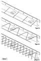
- the Figures 7a to 7c represent other examples of bidirectional lattice type beams.
Landscapes
- Engineering & Computer Science (AREA)
- Architecture (AREA)
- Civil Engineering (AREA)
- Structural Engineering (AREA)
- Road Paving Structures (AREA)
- On-Site Construction Work That Accompanies The Preparation And Application Of Concrete (AREA)
- Seal Device For Vehicle (AREA)
Claims (10)
- System zum Übertragen von Lasten zwischen zwei aneinandergrenzenden Plattenelementen (A, B) aus Ortbeton, wobei das System aufweist:- zwei Flachstahlprofile (5.3, 5.4), die dazu bestimmt sind, die Ecken zwischen der horizontal verlaufenden Plattenfläche entlang einer x-und einer y-Achse und der vertikal verlaufenden Ebene der Fuge entlang einer z-Achse zu verstärken;- Keilverbindungsplatten (5.7, 6.3), die dazu bestimmt sind, das Übertragen von vertikalen Lasten entlang der z-Achse zu ermöglichen und dabei den Plattenelementen die freie Bewegung entlang der x- und der y-Achse zu gestatten,- ein Blech (5.1, 6.2), das dazu bestimmt ist, das Einschalen der Ränder der Platten zu gewährleisten,dadurch gekennzeichnet, dass das System ferner zwei gitterartige, bidirektionale Träger (5.8) aufweist, die dazu bestimmt sind, die Flachprofile (5.3, 5.4) zu versteifen, um zu vermeiden, dass die Profile sich verwinden, wobei jeder Träger dabei zugleich eine Verbindung jeweils zwischen einem Profil und einem Plattenelement gewährleistet.
- System nach Anspruch 1,
dadurch gekennzeichnet, dass den Keilverbindungsplatten (6.3) Hülsen (6.1) zugeordnet sind, so dass sie die Verriegelung der beiden Plattenelemente (A, B) entlang der z-Achse ermöglichen und dabei eine freie relative Bewegung zwischen den Plattenelementen entlang der x- und der y-Achse gestatten. - System nach Anspruch 2,
dadurch gekennzeichnet , dass jede Hülse aus Metall besteht und einen rechteckigen Querschnitt hat und mit dem Schalungsblech (5.1, 6.2) senkrecht zu diesem Blech verschweißt ist, indem sie in dem Gießbereich (A) der Plattenelemente liegt, während jede Keilverbindungsplatte (5.7, 6.3) aus Stahl besteht, einen rechteckigen Querschnitt hat, in eine jeweilige Hülse eingeschoben ist und sich in den Gießbereich des anderen Plattenelements (B) fortsetzt und fest damit verbunden ist. - System nach Anspruch 3,
dadurch gekennzeichnet , dass die Abmessung (h) einer jeden Keilverbindungsplatte eine Gleitbewegung ohne Spiel gegenüber der Abmessung (H) innerhalb der zugeordneten Hülse parallel zur z-Achse ermöglicht, wobei die Abmessung (1) der Keilverbindungsplatte deutlich geringer als die Innenabmessung (L) der Hülse parallel zur x-Achse ist. - System nach Anspruch 3 oder Anspruch 4,
dadurch gekennzeichnet , dass jede Keilverbindungsplatte (6.3) mit Hilfe von Bolzen (6.4) aus "Nylon" mit geringem Querschnitt in der zugeordneten Hülse (6.1) in Stellung gehalten wird, die dazu bestimmt sind, bei Schwindung des Betons zu brechen. - System nach einem der Ansprüche 3 bis 5,
dadurch gekennzeichnet , dass ein Haftstreifen vorgesehen ist, um das Eindringen von Beton in die Aussparung zu vermeiden, die sich zwischen den Seitenwänden einer jeden Keilverbindungsplatte (6.3) und denen der zugeordneten Hülse (6.1) befindet. - System nach Anspruch 5,
dadurch gekennzeichnet , dass derjenige Teil einer jeden Keilverbindungsplatte (6.3), der sich in dem anderen Plattenelement (B) befindet, fest mit diesem Plattenelement verbunden ist, während derjenige Teil der Keilverbindungsplatte, der sich in dem einen Plattenelement (A) befindet, nach dem Brechen der Bolzen (6.4) in einer horizontal verlaufenden Ebene entlang der x- und der y-Achse innerhalb der entsprechenden Hülse (6.1) freigegeben ist, jedoch in einer vertikal verlaufenden Ebene entlang der z-Achse verkeilt ist. - System nach einem der Ansprüche 1 bis 7,
dadurch gekennzeichnet , dass die beiden Profile (5.3, 5.4) über Bolzen (5.6) aus einem nylonartigen Material vorläufig miteinander verbunden sind, die dazu bestimmt sind, bei Schwindung des Betons zu brechen. - System nach einem der Ansprüche 1 bis 8,
dadurch gekennzeichnet , dass es ferner Zwischenanker (5.5) jeweils zur Ergänzung zwischen Flachprofil und jeweiligem Plattenelement (A, B) aufweist. - System nach einem der Ansprüche 1 bis 9,
dadurch gekennzeichnet , dass es ferner einen Einstellzylinder (5.2) aufweist, der die Höheneinstellung der Fuge ermöglicht.
Applications Claiming Priority (3)
| Application Number | Priority Date | Filing Date | Title |
|---|---|---|---|
| FR0216060A FR2848581A1 (fr) | 2002-12-17 | 2002-12-17 | Systeme pour transferer les charges entre des dalles coulees en place |
| FR0216060 | 2002-12-17 | ||
| PCT/FR2003/003701 WO2004065694A1 (fr) | 2002-12-17 | 2003-12-12 | Syteme pour transferer les charges entre des dalles coulees en place |
Publications (2)
| Publication Number | Publication Date |
|---|---|
| EP1579075A1 EP1579075A1 (de) | 2005-09-28 |
| EP1579075B1 true EP1579075B1 (de) | 2012-05-09 |
Family
ID=32338926
Family Applications (1)
| Application Number | Title | Priority Date | Filing Date |
|---|---|---|---|
| EP03815398A Expired - Lifetime EP1579075B1 (de) | 2002-12-17 | 2003-12-12 | System zur übertragung von lasten zwischen ortbetoniertenplatten |
Country Status (5)
| Country | Link |
|---|---|
| EP (1) | EP1579075B1 (de) |
| AT (1) | ATE557132T1 (de) |
| AU (1) | AU2003300592A1 (de) |
| FR (1) | FR2848581A1 (de) |
| WO (1) | WO2004065694A1 (de) |
Families Citing this family (28)
| Publication number | Priority date | Publication date | Assignee | Title |
|---|---|---|---|---|
| US7481031B2 (en) | 2001-09-13 | 2009-01-27 | Russell Boxall | Load transfer plate for in situ concrete slabs |
| BE1016147A3 (fr) * | 2004-08-04 | 2006-04-04 | Coredis S A | Joint metallique allege pour surfaces en beton. |
| EP1801311A1 (de) * | 2005-12-21 | 2007-06-27 | MGSI- Acessorios Para Industrias, LDA | Schalungssystem für Platten |
| US7736088B2 (en) | 2006-07-13 | 2010-06-15 | Russell Boxall | Rectangular load plate |
| PT104132A (pt) * | 2008-07-16 | 2010-01-18 | Mgsi Acessorios Para Ind Lda | Aperfeiçoamentos num sistema de cofragem de pavimentos |
| GB201115940D0 (en) * | 2011-09-14 | 2011-10-26 | Permaban Ltd | Movement joint |
| AR090164A1 (es) * | 2012-02-27 | 2014-10-22 | Hengelhoef Concrete Joints Mfg Nv | Junta de expansion |
| GB201203580D0 (en) * | 2012-02-29 | 2012-04-11 | Permaban Ltd | Anti-spalling edging |
| CN103485423B (zh) * | 2013-09-26 | 2015-12-02 | 中国华冶科工集团有限公司 | 后浇带留置的方法 |
| US10077551B2 (en) | 2015-10-05 | 2018-09-18 | Illinois Tool Works Inc. | Joint edge assembly and method for forming joint in offset position |
| US10119281B2 (en) | 2016-05-09 | 2018-11-06 | Illinois Tool Works Inc. | Joint edge assembly and formwork for forming a joint, and method for forming a joint |
| US10590643B2 (en) | 2016-11-16 | 2020-03-17 | Illinois Tool Works Inc. | Load transfer plate and load transfer plate pocket and method of employing same |
| US10533292B2 (en) | 2016-12-20 | 2020-01-14 | Illinois Tool Works Inc. | Load transfer plate and method of employing same |
| AU2018226389B2 (en) | 2017-10-13 | 2024-09-12 | Illinois Tool Works Inc. | Edge protection system having bridging pins |
| AU2018226394B2 (en) | 2017-10-13 | 2024-09-12 | Illinois Tool Works Inc. | Edge protection system having clip retainment |
| AU2018226391B2 (en) | 2017-10-13 | 2024-10-10 | Illinois Tool Works Inc. | Edge protection system having support foot |
| AU2018226393B2 (en) | 2017-10-13 | 2024-09-26 | Illinois Tool Works Inc. | Edge protection system with intersection module |
| AU2018226390B2 (en) | 2017-10-13 | 2024-09-19 | Illinois Tool Works Inc. | Edge protection system having retaining clip |
| AU2018226392B2 (en) | 2017-10-13 | 2024-10-10 | Illinois Tool Works Inc. | Edge protection system having dowel plate |
| AU2019264633B2 (en) | 2018-11-19 | 2025-08-07 | Illinois Tool Works Inc. | Support bracket |
| USD922719S1 (en) | 2019-12-20 | 2021-06-15 | Illinois Tool Works Inc. | Load transfer plate pocket |
| US11041318B1 (en) | 2019-12-20 | 2021-06-22 | Illinois Tool Works Inc. | Load transfer plate apparatus |
| AU2021204996A1 (en) | 2021-07-12 | 2023-02-02 | Illinois Tool Works Inc. | An armoured joint – anti-skew stake bracket |
| AU2021204995A1 (en) | 2021-07-12 | 2023-02-02 | Illinois Tool Works Inc. | An edge protection system – joint orientation marker |
| AU2021204992A1 (en) | 2021-07-12 | 2023-02-02 | Illinois Tool Works Inc. | An armoured joint – disruptive folded anchor rail |
| AU2021204994A1 (en) | 2021-07-12 | 2023-02-02 | Illinois Tool Works Inc. | An edge protection system – intersection continuous perimeter joint line |
| AU2021204993A1 (en) | 2021-07-12 | 2023-02-02 | Illinois Tool Works Inc. | An edge protection system – floating cover plate on intersection |
| PL131556U1 (pl) * | 2023-07-13 | 2025-01-20 | Świderski Adam Aspuro | Zespół listwy dylatacyjnej |
Family Cites Families (8)
| Publication number | Priority date | Publication date | Assignee | Title |
|---|---|---|---|---|
| US3018703A (en) * | 1958-05-23 | 1962-01-30 | Servicised Products Corp | Joint sealing device |
| SE500738C2 (sv) * | 1992-12-17 | 1994-08-22 | Sven Gunnar Joensson | Anordning för fogar i betonggolv |
| BE1012984A3 (fr) * | 1998-04-29 | 2001-07-03 | Eurosteel Sa | Joint de structure pour dalles en materiau moulable. |
| FI110631B (fi) * | 1998-10-20 | 2003-02-28 | Teraespeikko Oy | Menetelmä maanvaraisen betonilaattakentän valmistamiseksi ja maanvarainen betonilaattakenttä |
| FR2785632A1 (fr) * | 1998-11-10 | 2000-05-12 | Ppc Sa | Joint de dilatation |
| FR2812891B1 (fr) * | 2000-08-11 | 2003-12-19 | Freyssinet Int Stup | Dispositif d'assemblage de dalles de beton et procede de reparation de surfaces de roulement, utilisant ce dispositif |
| ITRM20020070A1 (it) * | 2002-02-11 | 2003-08-11 | Maurizio Pontello | Giunto di dilatazione per pavimentazioni in calcestruzzo e simili. |
| DE20209995U1 (de) * | 2002-06-28 | 2002-11-21 | Ed. Züblin AG, 70567 Stuttgart | Betonierfugenausbildung in der Bodenplatte |
-
2002
- 2002-12-17 FR FR0216060A patent/FR2848581A1/fr not_active Withdrawn
-
2003
- 2003-12-12 AU AU2003300592A patent/AU2003300592A1/en not_active Abandoned
- 2003-12-12 EP EP03815398A patent/EP1579075B1/de not_active Expired - Lifetime
- 2003-12-12 AT AT03815398T patent/ATE557132T1/de active
- 2003-12-12 WO PCT/FR2003/003701 patent/WO2004065694A1/fr not_active Ceased
Also Published As
| Publication number | Publication date |
|---|---|
| ATE557132T1 (de) | 2012-05-15 |
| WO2004065694A1 (fr) | 2004-08-05 |
| FR2848581A1 (fr) | 2004-06-18 |
| EP1579075A1 (de) | 2005-09-28 |
| AU2003300592A1 (en) | 2004-08-13 |
Similar Documents
| Publication | Publication Date | Title |
|---|---|---|
| EP1579075B1 (de) | System zur übertragung von lasten zwischen ortbetoniertenplatten | |
| US6354053B1 (en) | Structural joint for slabs in moldable material | |
| BE679420A (de) | ||
| KR101840763B1 (ko) | T형 고정브라켓을 구비한 캔틸레버교량 시공방법 | |
| KR102421682B1 (ko) | 전단면 프리캐스트 바닥판, 이를 포함하는 하이브리드 바닥판 및 이를 포함하는 교량 상부구조의 제작방법 | |
| JP7168429B2 (ja) | 床型枠材 | |
| CN209779707U (zh) | 基础底板后浇带的止水钢板支撑结构 | |
| KR101606439B1 (ko) | 트러스거더와 데크플레이트 간의 결합용 스페이서 | |
| KR101098998B1 (ko) | 재활용가능한 하이브리드형 철골보 접합기구 및 이를 이용한 철골보 접합방법 | |
| KR102427300B1 (ko) | 연속화슬래브를 이용한 프리캐스트 슬래브교량 및 그 시공 방법 | |
| EP0603060B1 (de) | Vorgefertigte Deckplatte und Verfahren zum Herstellen einer Brücke mit solchen Platten | |
| JP2842829B2 (ja) | コンクリート製品並びにその製造方法及び使用方法 | |
| KR102026976B1 (ko) | T형 고정브라켓을 구비한 캔틸레버교량 | |
| US20140027940A1 (en) | Form, system and method for forming concrete diaphragms | |
| KR101012010B1 (ko) | 골형 웨브 강판 조립보 | |
| JP2016084629A (ja) | インバート用型枠 | |
| JP3590786B2 (ja) | 竹割型坑門用外型枠とその施工方法 | |
| JP5406896B2 (ja) | 道路橋継目部の止水構造及び止水工法 | |
| FR2873727A1 (fr) | Procede pour limiter les ponts thermiques lors de l'edification de parois de construction mettant en oeuvre des armatures de reprise vissees | |
| CN107687256B (zh) | 装配式混凝土结构主次梁连接一体化支撑系统及安装方法 | |
| JP6650775B2 (ja) | 側溝の嵩上げ構築用部材 | |
| JP2005290818A (ja) | ダム施工用pc傾斜型枠とダム堤体などの施工方法 | |
| KR102272531B1 (ko) | 강관삽입형 결합에 의해 터널라이닝과 구조적으로 일체화된 격자지보시스템 | |
| KR102301622B1 (ko) | 합성 라멘교 및 이의 시공 방법, 합성 라멘교용 강거더 | |
| FR2500038A1 (fr) | Poutre prefabriquee, destinee notamment au maintien des dalles dont l'assemblage forme les murs d'un batiment |
Legal Events
| Date | Code | Title | Description |
|---|---|---|---|
| PUAI | Public reference made under article 153(3) epc to a published international application that has entered the european phase |
Free format text: ORIGINAL CODE: 0009012 |
|
| 17P | Request for examination filed |
Effective date: 20050610 |
|
| AK | Designated contracting states |
Kind code of ref document: A1 Designated state(s): AT BE BG CH CY CZ DE DK EE ES FI FR GB GR HU IE IT LI LU MC NL PT RO SE SI SK TR |
|
| AX | Request for extension of the european patent |
Extension state: AL LT LV MK |
|
| DAX | Request for extension of the european patent (deleted) | ||
| 17Q | First examination report despatched |
Effective date: 20061121 |
|
| GRAP | Despatch of communication of intention to grant a patent |
Free format text: ORIGINAL CODE: EPIDOSNIGR1 |
|
| GRAS | Grant fee paid |
Free format text: ORIGINAL CODE: EPIDOSNIGR3 |
|
| GRAA | (expected) grant |
Free format text: ORIGINAL CODE: 0009210 |
|
| AK | Designated contracting states |
Kind code of ref document: B1 Designated state(s): AT BE BG CH CY CZ DE DK EE ES FI FR GB GR HU IE IT LI LU MC NL PT RO SE SI SK TR |
|
| REG | Reference to a national code |
Ref country code: GB Ref legal event code: FG4D Free format text: NOT ENGLISH |
|
| REG | Reference to a national code |
Ref country code: AT Ref legal event code: REF Ref document number: 557132 Country of ref document: AT Kind code of ref document: T Effective date: 20120515 Ref country code: CH Ref legal event code: EP |
|
| REG | Reference to a national code |
Ref country code: IE Ref legal event code: FG4D Free format text: LANGUAGE OF EP DOCUMENT: FRENCH |
|
| REG | Reference to a national code |
Ref country code: DE Ref legal event code: R096 Ref document number: 60340933 Country of ref document: DE Effective date: 20120705 |
|
| REG | Reference to a national code |
Ref country code: NL Ref legal event code: VDEP Effective date: 20120509 |
|
| PG25 | Lapsed in a contracting state [announced via postgrant information from national office to epo] |
Ref country code: CY Free format text: LAPSE BECAUSE OF FAILURE TO SUBMIT A TRANSLATION OF THE DESCRIPTION OR TO PAY THE FEE WITHIN THE PRESCRIBED TIME-LIMIT Effective date: 20120509 Ref country code: FI Free format text: LAPSE BECAUSE OF FAILURE TO SUBMIT A TRANSLATION OF THE DESCRIPTION OR TO PAY THE FEE WITHIN THE PRESCRIBED TIME-LIMIT Effective date: 20120509 Ref country code: SE Free format text: LAPSE BECAUSE OF FAILURE TO SUBMIT A TRANSLATION OF THE DESCRIPTION OR TO PAY THE FEE WITHIN THE PRESCRIBED TIME-LIMIT Effective date: 20120509 |
|
| REG | Reference to a national code |
Ref country code: AT Ref legal event code: MK05 Ref document number: 557132 Country of ref document: AT Kind code of ref document: T Effective date: 20120509 |
|
| PG25 | Lapsed in a contracting state [announced via postgrant information from national office to epo] |
Ref country code: PT Free format text: LAPSE BECAUSE OF FAILURE TO SUBMIT A TRANSLATION OF THE DESCRIPTION OR TO PAY THE FEE WITHIN THE PRESCRIBED TIME-LIMIT Effective date: 20120910 Ref country code: GR Free format text: LAPSE BECAUSE OF FAILURE TO SUBMIT A TRANSLATION OF THE DESCRIPTION OR TO PAY THE FEE WITHIN THE PRESCRIBED TIME-LIMIT Effective date: 20120810 Ref country code: SI Free format text: LAPSE BECAUSE OF FAILURE TO SUBMIT A TRANSLATION OF THE DESCRIPTION OR TO PAY THE FEE WITHIN THE PRESCRIBED TIME-LIMIT Effective date: 20120509 |
|
| PG25 | Lapsed in a contracting state [announced via postgrant information from national office to epo] |
Ref country code: SK Free format text: LAPSE BECAUSE OF FAILURE TO SUBMIT A TRANSLATION OF THE DESCRIPTION OR TO PAY THE FEE WITHIN THE PRESCRIBED TIME-LIMIT Effective date: 20120509 Ref country code: DK Free format text: LAPSE BECAUSE OF FAILURE TO SUBMIT A TRANSLATION OF THE DESCRIPTION OR TO PAY THE FEE WITHIN THE PRESCRIBED TIME-LIMIT Effective date: 20120509 Ref country code: NL Free format text: LAPSE BECAUSE OF FAILURE TO SUBMIT A TRANSLATION OF THE DESCRIPTION OR TO PAY THE FEE WITHIN THE PRESCRIBED TIME-LIMIT Effective date: 20120509 Ref country code: AT Free format text: LAPSE BECAUSE OF FAILURE TO SUBMIT A TRANSLATION OF THE DESCRIPTION OR TO PAY THE FEE WITHIN THE PRESCRIBED TIME-LIMIT Effective date: 20120509 Ref country code: CZ Free format text: LAPSE BECAUSE OF FAILURE TO SUBMIT A TRANSLATION OF THE DESCRIPTION OR TO PAY THE FEE WITHIN THE PRESCRIBED TIME-LIMIT Effective date: 20120509 Ref country code: EE Free format text: LAPSE BECAUSE OF FAILURE TO SUBMIT A TRANSLATION OF THE DESCRIPTION OR TO PAY THE FEE WITHIN THE PRESCRIBED TIME-LIMIT Effective date: 20120509 Ref country code: RO Free format text: LAPSE BECAUSE OF FAILURE TO SUBMIT A TRANSLATION OF THE DESCRIPTION OR TO PAY THE FEE WITHIN THE PRESCRIBED TIME-LIMIT Effective date: 20120509 |
|
| PG25 | Lapsed in a contracting state [announced via postgrant information from national office to epo] |
Ref country code: IT Free format text: LAPSE BECAUSE OF FAILURE TO SUBMIT A TRANSLATION OF THE DESCRIPTION OR TO PAY THE FEE WITHIN THE PRESCRIBED TIME-LIMIT Effective date: 20120509 |
|
| PLBE | No opposition filed within time limit |
Free format text: ORIGINAL CODE: 0009261 |
|
| STAA | Information on the status of an ep patent application or granted ep patent |
Free format text: STATUS: NO OPPOSITION FILED WITHIN TIME LIMIT |
|
| 26N | No opposition filed |
Effective date: 20130212 |
|
| PG25 | Lapsed in a contracting state [announced via postgrant information from national office to epo] |
Ref country code: ES Free format text: LAPSE BECAUSE OF FAILURE TO SUBMIT A TRANSLATION OF THE DESCRIPTION OR TO PAY THE FEE WITHIN THE PRESCRIBED TIME-LIMIT Effective date: 20120820 |
|
| REG | Reference to a national code |
Ref country code: DE Ref legal event code: R097 Ref document number: 60340933 Country of ref document: DE Effective date: 20130212 |
|
| BERE | Be: lapsed |
Owner name: GSE Effective date: 20121231 |
|
| PG25 | Lapsed in a contracting state [announced via postgrant information from national office to epo] |
Ref country code: MC Free format text: LAPSE BECAUSE OF NON-PAYMENT OF DUE FEES Effective date: 20121231 Ref country code: BG Free format text: LAPSE BECAUSE OF FAILURE TO SUBMIT A TRANSLATION OF THE DESCRIPTION OR TO PAY THE FEE WITHIN THE PRESCRIBED TIME-LIMIT Effective date: 20120809 |
|
| REG | Reference to a national code |
Ref country code: CH Ref legal event code: PL |
|
| GBPC | Gb: european patent ceased through non-payment of renewal fee |
Effective date: 20121212 |
|
| REG | Reference to a national code |
Ref country code: IE Ref legal event code: MM4A |
|
| PG25 | Lapsed in a contracting state [announced via postgrant information from national office to epo] |
Ref country code: BE Free format text: LAPSE BECAUSE OF NON-PAYMENT OF DUE FEES Effective date: 20121231 |
|
| PG25 | Lapsed in a contracting state [announced via postgrant information from national office to epo] |
Ref country code: LI Free format text: LAPSE BECAUSE OF NON-PAYMENT OF DUE FEES Effective date: 20121231 Ref country code: IE Free format text: LAPSE BECAUSE OF NON-PAYMENT OF DUE FEES Effective date: 20121212 Ref country code: CH Free format text: LAPSE BECAUSE OF NON-PAYMENT OF DUE FEES Effective date: 20121231 |
|
| PG25 | Lapsed in a contracting state [announced via postgrant information from national office to epo] |
Ref country code: GB Free format text: LAPSE BECAUSE OF NON-PAYMENT OF DUE FEES Effective date: 20121212 |
|
| PGFP | Annual fee paid to national office [announced via postgrant information from national office to epo] |
Ref country code: DE Payment date: 20131210 Year of fee payment: 11 Ref country code: FR Payment date: 20131021 Year of fee payment: 11 |
|
| PG25 | Lapsed in a contracting state [announced via postgrant information from national office to epo] |
Ref country code: TR Free format text: LAPSE BECAUSE OF FAILURE TO SUBMIT A TRANSLATION OF THE DESCRIPTION OR TO PAY THE FEE WITHIN THE PRESCRIBED TIME-LIMIT Effective date: 20120509 |
|
| PG25 | Lapsed in a contracting state [announced via postgrant information from national office to epo] |
Ref country code: LU Free format text: LAPSE BECAUSE OF NON-PAYMENT OF DUE FEES Effective date: 20121212 |
|
| PG25 | Lapsed in a contracting state [announced via postgrant information from national office to epo] |
Ref country code: HU Free format text: LAPSE BECAUSE OF FAILURE TO SUBMIT A TRANSLATION OF THE DESCRIPTION OR TO PAY THE FEE WITHIN THE PRESCRIBED TIME-LIMIT Effective date: 20031212 |
|
| REG | Reference to a national code |
Ref country code: DE Ref legal event code: R119 Ref document number: 60340933 Country of ref document: DE |
|
| REG | Reference to a national code |
Ref country code: FR Ref legal event code: ST Effective date: 20150831 |
|
| PG25 | Lapsed in a contracting state [announced via postgrant information from national office to epo] |
Ref country code: DE Free format text: LAPSE BECAUSE OF NON-PAYMENT OF DUE FEES Effective date: 20150701 |
|
| PG25 | Lapsed in a contracting state [announced via postgrant information from national office to epo] |
Ref country code: FR Free format text: LAPSE BECAUSE OF NON-PAYMENT OF DUE FEES Effective date: 20141231 |