EP0320496B1 - Gerät zum automatischen Melken von Tieren - Google Patents
Gerät zum automatischen Melken von Tieren Download PDFInfo
- Publication number
- EP0320496B1 EP0320496B1 EP89101861A EP89101861A EP0320496B1 EP 0320496 B1 EP0320496 B1 EP 0320496B1 EP 89101861 A EP89101861 A EP 89101861A EP 89101861 A EP89101861 A EP 89101861A EP 0320496 B1 EP0320496 B1 EP 0320496B1
- Authority
- EP
- European Patent Office
- Prior art keywords
- animal
- milking
- mechanical sensors
- elements
- parlour
- Prior art date
- Legal status (The legal status is an assumption and is not a legal conclusion. Google has not performed a legal analysis and makes no representation as to the accuracy of the status listed.)
- Expired - Lifetime
Links
Images


Classifications
-
- A—HUMAN NECESSITIES
- A01—AGRICULTURE; FORESTRY; ANIMAL HUSBANDRY; HUNTING; TRAPPING; FISHING
- A01J—MANUFACTURE OF DAIRY PRODUCTS
- A01J5/00—Milking machines or devices
- A01J5/017—Automatic attaching or detaching of clusters
- A01J5/0175—Attaching of clusters
-
- A—HUMAN NECESSITIES
- A01—AGRICULTURE; FORESTRY; ANIMAL HUSBANDRY; HUNTING; TRAPPING; FISHING
- A01K—ANIMAL HUSBANDRY; CARE OF BIRDS, FISHES, INSECTS; FISHING; REARING OR BREEDING ANIMALS, NOT OTHERWISE PROVIDED FOR; NEW BREEDS OF ANIMALS
- A01K1/00—Housing animals; Equipment therefor
- A01K1/12—Milking stations
Definitions
- the invention relates to a device for automatically milking animals, comprising a milking parlour bounded on at least two sides by guide means between which the animal can be positioned, detection means for determining the position of the animal or the position of specific parts of the animal relative to the milking parlour and means for attaching a milking cluster to the udder of the animal.
- a device for automatically milking animals comprising a milking parlour bounded on at least two sides by guide means between which the animal can be positioned, detection means for determining the position of the animal or the position of specific parts of the animal relative to the milking parlour and means for attaching a milking cluster to the udder of the animal.
- a milking device comprises a milking parlour where the animal is stationed during milking.
- the milking parlour must be such, that the animal feels comfortable there.
- the animal can be fed in the milking parlour with concentrated fodder, the fodder being fed depending on the specific animal.
- the guide means may be in the form of a rail system around or on both sides of the animal.
- the milking cluster is applied in the correct manner.
- the milking parlour has a lateral boundary which is contiguous to the animal, it may be assumed that the udder is substantially in the centre between the lateral guide means of the milking parlour. If, additionally, it is known how much space there is between the udder and the posterior of the relevant animal, an arm supporting the milking cluster can be moved between the legs of the animal from the rear forwardly until a stop provided on that arm touches the posterior of the animal, whereafter the milking cluster is attached by an upward movement of the arm.
- the distance between the milking cluster and the stop provided on the arm must be adjusted to the the milking cluster is attached by an upward movement of the arm.
- the distance between the milking cluster and the stop provided on the arm must be adjusted to the correct length.
- the lateral guide means of the milking parlour must allow adequate room for each animal, so that a number of animals which are narrower than the distance between the guide means cannot be accurately stationed in the centre of the milking parlour. This can however be somewhat corrected in that the milking cluster moves between the hind legs of the animal, as a result of which the animal will tend to move to the centre. Nevertheless it remains an uncomfortable situation for the animal.
- the invention has for its object to provide a device for automatically milking animals, such as cows, in which the position of the animal can be determined in a manner that the milking cluster can be attached efficiently.
- the detection means comprises mechanical sensors which at least during the phase of the milking process in which the milking cluster has to be attached to the udder are constantly brought into contact with the animal's body, while furthermore a computer is provided in which data supplied by an animal identification system indicating the position of specific parts of the animal relative to the measuring point of the mechanical sensors is stored and which computer controls the means for positioning the milking cluster.
- Such mechanical sensors may be of a very light construction, so that it is hardly noticeable to the animal, the position of the mechanical sensors then being recorded and constituting an information on the basis of which the position of the animal can be determined.
- the mechanical sensors may be movable along the posterior of the animal, more specifically above the hind legs of the animal, for example on the most rearward portion of the animal.
- the mechanical sensors may be connected to a swivelling member which is capable of hinging around a substantially horizontal axis above the animal, the hinge axis being substantially transversely of the milking parlour. Then, according to a further characteristic of the invention, the mechanical sensors may rest against the posterior of the animal by its own weight, the angular position of the swivelling member then being a measure of the position of the animal.
- the mechanical sensors comprise rods, a first one of which can bear on the animal's side at the same level as the second one.
- the first rod can be fastened to the swivelling member and be at a substantially square angle to the second rod.
- the mechanical sensors are movable in substantially a lateral direction relative to the animal and along both sides of the animal; the mechanical sensors are intercoupled such that they move towards each other to substantially an equal extent. The animal will then assume a position in the centre of the milking parlour, the two mechanical sensors pushing equally on both sides against the animal. Should the animal move from this mid-position, it experiences an increased pressure from the guide member at the side to which it moves, so that the animal will tend to return to its original position.
- the mechanical sensors may be constituted by elements which, relative to the milking parlour, are arranged substantially in the longitudinal direction on both sides of the milking parlour and are capable of moving at their forwardly directed ends and are capable of hinging near their rearwardly directed ends around a substantially vertical axis.
- spring-loaded means may be present to push the mechanical sensors inwardly towards each other.
- the two mechanical sensors may be interconnected by a connecting member which acts on the elements in a hinging manner remote from the swivel axis of the elements, more specifically one element at the swivel axis side where the element is located and the other element through a lever at the remote side of the element relative to the swivel axis.
- stops may be provided against which one or both supports bear when there is no animal in the milking parlour, the elements being in a somewhat more inwardly directed position than when the animal were present.
- each individual teat cup of the milking cluster may be adjustable depending on the position of the teats of a specific animal. This position may however alter, depending on a number of factors or depending on the age of the animal.
- means are provided which, during the milking operations, record the positions of the teat cups and store them as data, with the object of using these data during a subsequent milking operation of the same animal in such a way that before the milking cluster is placed on the udder, the position of the teat cups is adjusted in accordance with the previously recorded position during milking of the same animal.
- the adjustment of the milking cluster for the relevant animal can be adapted thereto.
- a plurality of data of the animal to be milked may be stored.
- This data may contain the configuration (relative location and/or position) of the teats, the position of the teats relative to a reference point, preferably one of the teats, the horizontal distance between the rear of the animal and a reference point near the udder, and/or the distance between a different detection point and the reference point, and the horizontally measured distance between the side of the animal and a reference point at the udder.
- the computer can derive the relevant control signals for the means for positioning the milking cluster.
- the computer can store the time elapsed between milking operations of the same animal.
- Such an information may be important in connection with the quantity of fodder the animals is fed during milking, but also in connection with the expected quantity of milk and the degree to which the udder is filled.
- This last item may affect the position and the location of the teats, so that these data can be taken into account in the determination of the actions to be performed for attaching the milking cluster.
- Figure 1 shows in a plan view a cow 1, stationed in the milking parlour.
- the milking parlour is bounded on both sides by guide rails 2, between which the animal can walk forwards until its head reaches the manger 3; the animal 1 will stop then.
- a mechanism 5 is provided for this purpose, which comprises a swivel arm 6 which is capable of hinging around a substantially horizontal pin 7, and whose other end is provided with a rod like mechanical sensor 8 fastened to the swivel arm at a substantially square angle.
- the rod 8 has a movable mechanical sensor 9 which can be moved along the rod 8 until it comes to bear on the animal (as is shown in Figure 1).
- the rod 8 is provided with a toothed rack 10, whilst sensor 9 includes an electric motor 11.
- the sensor 9 is moved along the rod 8 until the sensor touches the animal 1, means, not further shown, being present for switching off the electric motor 11 when sensor 9 experiences a slight resistance during its travel.
- the lateral position of the animal 1 can be determined.
- the rod 8 is rotated around a hinge pin 7, so that it bears against the posterior of the animal 1.
- the angular position then obtained for the swivel arm 6 determines the position of the cow in the forward direction.
- the computer 12 which is shown schematically in Figure 1. If it is furthermore known which cow is in the milking parlour, the computer can determine with an adequate degree of accuracy in what way the milking cluster 4 is to be attached.
- the animal carries identification means which, in the embodiments shown in the Figures 1 and 2, are constituted by an information carrier 14 fastened to a collar 13.
- This information carrier 14 is, for example, a small transmitter, whose signals can be picked up by a sensor connected to the computer and present in the milking parlour.
- the milking cluster 4 can be moved to the relevant position with the aid of the support 15.
- a frame 16 is provided which is fastened to the floor by means of legs 17.
- the support 15 is fastened capable of hinging, around the substantially vertical pin 18 to the frame 16; rotation around hinge pin 18 is effected by the adjusting device 19, for example a pneumatic or hydraulic cylinder unit.
- the support 15 includes a rod 21, having a toothed rack 22, with the aid of which the rod 21 can be moved in its longitudinal direction relative to the frame. Using these two displacement modes, swivelling around the vertical pin 18 and longitudinal movement of the rod 21, the milking cluster 4 can be adjusted to any desired position in a horizontal plane.
- FIG. 3 shows the milking cluster 4 having four teat cups 23 which together are supported in the support 15.
- the hollow bar of the frame 16 is shown in a cross-sectional view.
- a support 24 is provided on this hollow bar 16, which support is capable of swivelling relative to the bar around the hinge pin 18, using an actuating device 19, which is only partly shown.
- the support 24 is connected to the support 15 by means of a substantially horizontal hinge pin 25, around which portion 26 of the support is swivable.
- actuating device 27 which comprises, for example, a pneumatic or hydraulic cylinder and is connected by means of ball joints 28 to the frame 16 and also to portion 26 of the support.
- the portion 26 of the support 15 can consequently rotate around both the vertical pin 18 and the horizontal pin 25.
- Figure 3 shows the electric motor 29, for example a stepper motor, which has on its axle a pinion 30 which cooperates with the toothed rack 22 so as to move rod 21 in its longitudinal direction, causing the milking cluster 31 provided at the end of the rod 21 to be moved to under the animal.
- the milking cluster holder 31 is connected, capable of hinging around shaft 32, to the rod 21 through a fork 33, as a result of which the milking cluster holder remains at all times in a horizontal position.
- the milking cluster can be adjusted to any desired position by means of an appropriate control of the adjusting devices 19 and 27, and the electric motor 29.
- Figure 3 also shows the manner in which the teat cups 23 may be arranged in the milking cluster holder 31.
- the wider portion of the flaring teat cup 23 is supported in a recess of the milking cluster holder 31, so that the teat cups can be freely move up, thus getting free from the milking cluster holder 31.
- Releasing the cups from the milking cluster holder can be effected after the milking cluster has been attached to the udder and the vacuum has been generated, causing the teat cups to remain attached to the teats, by moving the milking cluster holder downwards.
- the tubes 39 connecting the teat cups 23 to the milking machine are adequately flexible, the teat cups 23, after having been lifted from the milking cluster holder 31, have a certain degree of freedom to follow the motions of the animal. After milking has been terminated the vacuum is terminated, which causes the teat cups 23 to fall automatically back into said recesses in the milking cluster holder.
- a computer-controlled quantity of fodder for example concentrate
- the manger 3 can be moved to a position outside the milking parlour.
- the animal can leave the milking parlour in the forward direction after milking has been terminated.
- the next animal is already present between the guide rails 2, but at some distance from the milking parlour.
- This animal can move up to the milking parlour, lured there by the manger 3, after the mechanism 5 has been moved upwards around a hinge pin 7, and the partition 36 which is connected through the rod system 37 to the frame 16 has been moved to a position outside the guide rails by means of actuating device 38.
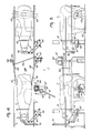
- the Figures 4 and 5 show a second embodiment of the device for milking an animal.
- This device also includes guide rails 2 at both sides of the milking parlour, the guide rails extending beyond a washing station which the animal has to pass before it arrives in the milking parlour.
- a manger 3 which, by means of a rod system 34 and an adjusting mechanism 35 can be moved to outside the area bounded by the guide rails 2.
- the animal is moved in the appropriate position by means of two positioning means 51, 52, which bear on either side against the animal 1, if the animal is halfway between the guide rails 2.
- the mechanical sensors or positioning members 51, 52 are interconnected such by means of a connecting rod 53 that they can move symmetrically relative to the milking parlour.
- a connecting rod 53 To that end positioning member 51 is hingeable around a vertical pin 54, whilst positioning member 52 is hingeable around a vertical pin 55.
- Positioning member 52 is rigidly connected to lever 56, to whose end the connecting rod 53 is connected capable of hinging, the connecting rod 53 being connected at its other end, capable of hinging, to positioning member 51.
- tension spring 57 With the aid of tension spring 57, an inwardly directed force is exerted on the positioning members 51 and 52 and, in the absence of an animal in the milking parlour, the positioning members 51, 52 bear against the stops 58 and 59, respectively.
- a support 15 for the milking cluster 4 comprising a plate 61 attached to the floor on which plate means are provided for moving the milking cluster to any desired location in the same manner as described with reference to the first embodiment.
- the animal carries a collar 13 with an information a carrier 14 provided thereon, so that the sensor means, which are not shown, can inform the computer which animal is in the milking parlour. Depending on this information, the desired quantity of fodder can then be fed to the manger 3 and it can be determined to which position the milking cluster 4 is to be moved for correct attachment to the udder of the animal.
- the implement includes a washing station where the udders of the animal can be cleaned, rinsed, disinfected and/or dried, depending on the requirements, before the animal goes to the milking parlour.
- This washing operation can already be effected during milking of the preceding animal.
- a sensor 62 which detect the presence of said animal in the washing station.
- the animal is then in front of the partition 36 which is movable by means of rod system 37 from a position outside the guide rails 2 to a position between these guide rails.
- This partition 36 may also be provided with a manger so as to lure the animal in the appropriate position in the washing station.
- the washing station comprises a plurality of nozzles 63 which can spray the desired liquid, for example warm water, against the udder. Furthermore, drying can be performed by means of warm air blown against the udder.
- the milking parlour is also bounded by guide rails 2 between which the animal 1 is present. In this position the animal can take the fodder in the aforedescribed manner from the manger 3, which manger 3 can be moved to outside the guide rail- bounded area by means of rod system 34 and actuating mechanism 35.
- the milking parlour is bounded by a member 64 which can be moved by means of the rod system 65 and the actuating device 66 to outside the area bounded by the guide rails 2.
- the mechanism 64, 65, 66 is mounted on a beam 60 which is movable in the longitudinal direction relative to the milking parlour, so that the position of the bounding member 64 can be set in dependence on the length of the animal.
- the animal present in the milking parlour has a limited freedom of movement.
- the animal is provided with marking means 67, for example a metal plate, which is connected to the animal's back.
- Detection means 68 are arranged over the animal, with which the position of the marking means can be determined electronically, which position is conveyed to the computer.
- the computer can calculate the position of the udder, whereafter the support of the milking cluster 4 can be actuated so that the milking cluster can be connected to the udder in the correct way.
- the support comprises an arm 70 which is capable of rotation around a fixed, vertical pin 69.
- Arm 70 is connected to a second arm 72, but capable of swivelling around vertical pin 71.
- Arm 72 carries the milking cluster holder 31 at its end.
- the support can be adjusted for height by means of an electric motor in the region of hinge pin 69 and further positioning is effected by rotation around the pins 69 and 71.
- the Figures 6 and 7 also show a stop 73 against which the animal can bear through the upper part of its forelegs.
- the stop 73 can be hinged downwards, into the floor, by means of actuating device 74, whilst, depending on the relevant animal, the stop 73 can be adjusted to a predetermined position, to render it possible for the animal to eat in a comfortable position whilst yet still bearing against the stop 73.
- FIG 8 shows an embodiment of the device for milking an animal in which cleaning of the udder is done in the milking parlour.
- spraying apparatus 75, 76 are provided which can spray a detergent on the animal's udder, as is shown schematically.
- the milking cluster can be cleaned at the same time by having the spraying apparatus 75 squirt detergent also in the teat cups 23 of the milking cluster.
- the milking cluster can be tilted to its inverted position or - as is shown in Figure 8 - to a partly tilted position, so that the detergent squirted into the teat cups 23 can flow out again.
- rod 21 comprises a toothed rack 22 cooperating with a pinion gear 30, so that the rod 21 can be moved in its longitudinal direction.
- Figure 10 is a view along the arrow X in Figure 9.
- Figure 8 shows detection means including cells 80 which detect screening of the beams originating from radiation source 81, by the animal. It will be obvious that thus the position of at least the posterior of the animal can be accurately determined.
Claims (9)
dadurch gekennzeichnet, daß die Erkennungseinrichtung mechanische Sensoren (8, 9; 51, 52) umfaßt, die wenigstens während der Phase des Melkvorgangs, bei dem das Melkgeschirr an dem Euter angebracht sein muß, stets mit dem Körper des Tieres in Berührung gebracht sind, wobei außerdem ein Computer (12) vorgesehen ist, in dem von einem Tieridentifiziersystem gelieferte Daten gespeichert sind, die die Position spezieller Teile des Tieres relativ zu dem Meßpunkt der mechanischen Sensoren angeben, und daß der Computer die Einrichtung zum Positionieren des Melkgeschirrs (4) steuert.
dadurch gekennzeichnet, daß die mechanischen Sensoren (8, 9) längs des Hinterteils des Tieres, genauer gesagt über den Hinterbeinen des Tieres, zum Beispiel an der hintersten Stelle des Tieres beweglich sind.
dadurch gekennzeichnet, daß die mechanischen Sensoren (8, 9) mit einem Schwenkelement (6) verbunden sind, das um eine im wesentlichen horizontale Achse (7) über dem Tier schwenkbar ist.
dadurch gekennzeichnet, daß die mechanischen Sensoren (8, 9) durch ihr Eigengewicht an dem Hinterteil des Tieres anliegen, wobei die winkelmäßige Position des Schwenkelements (6) dann ein Maß für die Position des Tieres bildet.
dadurch gekennzeichnet, daß die mechanischen Sensoren Stangen (8, 9) umfassen, von denen eine erste (9) auf demselben Niveau wie die zweite (8) gegen die Seite des Tieres drükken kann, wobei die erste Stange (9) an dem Schwenkelement (6) anbringbar ist und sich im wesentlichen in einem rechten Winkel zu der zweiten Stange (8) anordnen läßt.
dadurch gekennzeichnet, daß die mechanischen Sensoren (51, 52) im wesentlichen in seitlicher Richtung relativ zu dem Tier sowie längs beider Seiten des Tieres beweglich sind, wobei die Sensoren (51, 52) derart miteinander gekoppelt sind, daß sie sich im wesentlichen im selben Ausmaß aufeinander zu bewegen.
dadurch gekennzeichnet, daß die mechanischen Sensoren durch Elemente (51, 52), die relativ zu dem Melkstand im wesentlichen in Längsrichtung auf beiden Seiten des Melkstands angeordnet sind und dazu ausgelegt sind, an ihren nach vorne gerichteten Enden eine Bewegung auszuführen und an ihren nach rückwärts gerichteten Enden um eine im wesentlichen vertikale Achse (54, 55) schwenkbar sind, sowie durch eine unter Federvorspannung stehende Einrichtung (57) zum Drücken der Elemente (51, 52) nach innen aufeinander zu gebildet sind.
dadurch gekennzeichnet, daß die beiden Elemente (51, 52) durch ein Verbindungsglied (53) miteinander verbunden sind, das von der Schwenkachse (54, 55) der Elemente (51, 52) abgelegen auf die Elemente (51, 52) schwenkend einwirkt, genauer gesagt auf das eine Element (51) auf der Seite der Schwenkachse (54), auf der sich das Element (51) befindet, und auf das andere Element (52) durch einen Hebel (56) auf der relativ zur Schwenkachse (55) von dem Element (52) abliegenden Seite.
dadurch gekennzeichnet, daß Anschläge (58, 59) vorgesehen sind, gegen die eines oder beide Elemente (51, 59) drücken, wenn sich kein Tier in dem Melkstand befindet, wobei sich die Elemente (51, 52) dann in einer etwas weiter nach innen gerichteten Position als bei anwesendem Tier befinden.
Priority Applications (2)
| Application Number | Priority Date | Filing Date | Title |
|---|---|---|---|
| EP89101861A EP0320496B2 (de) | 1985-01-16 | 1986-01-15 | Gerät zum automatischen Melken von Tieren |
| AT89101861T ATE83122T1 (de) | 1985-01-16 | 1986-01-15 | Geraet zum automatischen melken von tieren. |
Applications Claiming Priority (4)
| Application Number | Priority Date | Filing Date | Title |
|---|---|---|---|
| NL8500088A NL8500088A (nl) | 1985-01-16 | 1985-01-16 | Inrichting voor het automatisch melken van een dier. |
| NL8500088 | 1985-01-16 | ||
| EP89101861A EP0320496B2 (de) | 1985-01-16 | 1986-01-15 | Gerät zum automatischen Melken von Tieren |
| EP86200063A EP0188303B1 (de) | 1985-01-16 | 1986-01-15 | Gerät und Verfahren zum Melken von Tieren, wie z.B. Kühen |
Related Parent Applications (2)
| Application Number | Title | Priority Date | Filing Date |
|---|---|---|---|
| EP86200063A Division EP0188303B1 (de) | 1985-01-16 | 1986-01-15 | Gerät und Verfahren zum Melken von Tieren, wie z.B. Kühen |
| EP86200063.5 Division | 1986-01-15 |
Publications (4)
| Publication Number | Publication Date |
|---|---|
| EP0320496A2 EP0320496A2 (de) | 1989-06-14 |
| EP0320496A3 EP0320496A3 (en) | 1989-10-04 |
| EP0320496B1 true EP0320496B1 (de) | 1992-12-09 |
| EP0320496B2 EP0320496B2 (de) | 1999-09-15 |
Family
ID=26102927
Family Applications (2)
| Application Number | Title | Priority Date | Filing Date |
|---|---|---|---|
| EP89101862A Expired - Lifetime EP0319523B2 (de) | 1985-01-16 | 1986-01-15 | Gerät zum automatischen Melken von Tieren |
| EP89101861A Expired - Lifetime EP0320496B2 (de) | 1985-01-16 | 1986-01-15 | Gerät zum automatischen Melken von Tieren |
Family Applications Before (1)
| Application Number | Title | Priority Date | Filing Date |
|---|---|---|---|
| EP89101862A Expired - Lifetime EP0319523B2 (de) | 1985-01-16 | 1986-01-15 | Gerät zum automatischen Melken von Tieren |
Country Status (1)
| Country | Link |
|---|---|
| EP (2) | EP0319523B2 (de) |
Cited By (1)
| Publication number | Priority date | Publication date | Assignee | Title |
|---|---|---|---|---|
| US8662012B2 (en) | 2010-01-12 | 2014-03-04 | Delaval Holdings Ab | Positioning system for at least one flexible tubular element connected to a cup-shaped member |
Families Citing this family (30)
| Publication number | Priority date | Publication date | Assignee | Title |
|---|---|---|---|---|
| DE3931769C2 (de) * | 1989-09-25 | 2001-10-11 | Westfalia Landtechnik Gmbh | Vorrichtung zum maschinellen Melken von Tieren |
| NL9100992A (nl) * | 1991-06-10 | 1993-01-04 | Lely Nv C Van Der | Inrichting voor het melken van dieren. |
| GB9113405D0 (en) * | 1991-06-20 | 1991-08-07 | Silsoe Research Inst | Automatic milking |
| NL9200258A (nl) * | 1991-10-04 | 1993-05-03 | Lely Nv C Van Der | Werkwijze voor het reinigen van melkbekers en/of het nabehandelen van de spenen van een gemolken dier, inrichting voor het melken van dieren voor het toepassen van deze werkwijze(n), en spoelwerktuig toegepast in een dergelijke inrichting. |
| DE9219132U1 (de) * | 1991-10-04 | 1998-04-09 | Maasland Nv | Vorrichtung zum Melken von Tieren |
| NL9201128A (nl) * | 1992-06-25 | 1994-01-17 | Lely Nv C Van Der | Inrichting voor het automatisch melken van dieren, zoals koeien. |
| NL9300443A (nl) * | 1993-03-11 | 1994-10-03 | Prolion Bv | Werkwijze en inrichting voor het bewaken van dierfuncties. |
| NL9300578A (nl) * | 1993-04-01 | 1994-11-01 | Texas Industries Inc | Inrichting voor het automatisch melken van dieren. |
| NL9301377A (nl) * | 1993-08-09 | 1995-03-01 | Lely Nv C Van Der | Inrichting voor het automatisch melken van dieren. |
| NL9301414A (nl) * | 1993-08-16 | 1995-03-16 | Lely Nv C Van Der | Inrichting voor het automatisch melken van dieren. |
| NL9500362A (nl) * | 1994-04-14 | 1995-11-01 | Maasland Nv | Werkwijze voor het automatisch melken van dieren en inrichting waarin deze werkwijze kan worden toegepast. |
| SE9701310D0 (sv) † | 1997-04-11 | 1997-04-11 | Alfa Laval Agri Ab | A teatcup magazine, a milking arrangement, and a method of handling a teatcup |
| NL1009631C2 (nl) * | 1998-07-13 | 2000-01-17 | Gascoigne Melotte Bv | Inrichting en werkwijze voor het melken van een dier. |
| NL1015671C2 (nl) * | 2000-07-10 | 2002-01-11 | Lely Entpr Ag | Inrichting voor het automatisch melken van dieren. |
| US7290497B2 (en) * | 2001-09-21 | 2007-11-06 | Westfaliasurge, Inc. | Milking device provided with cleansing means |
| NL1017984C2 (nl) * | 2001-05-02 | 2002-11-05 | Idento Electronics Bv | Melkinrichting. |
| US10874084B2 (en) | 2004-06-12 | 2020-12-29 | Gea Farm Technologies, Inc. | Safety valve for a dairy system component |
| US8033247B2 (en) | 2004-06-12 | 2011-10-11 | Gea Farm Technologies, Inc. | Automatic dairy animal milker unit backflusher and teat dip applicator system and method |
| US8342125B2 (en) | 2004-06-12 | 2013-01-01 | Gea Farm Technologies, Inc. | Safety valve for an automatic dairy animal milker unit backflusher and teat dip applicator |
| US8117989B2 (en) | 2008-06-27 | 2012-02-21 | Gea Farm Technologies, Inc. | Milk tube dome with flow controller |
| US8025029B2 (en) | 2004-06-12 | 2011-09-27 | Gea Farm Technologies, Inc. | Automatic dairy animal milker unit backflusher and teat dip applicator system and method |
| EP2355652B2 (de) | 2008-11-10 | 2021-03-17 | GEA Farm Technologies GmbH | Verfahren und Vorrichtung zum automatischen inkontaktbringen eines Fluids mit den Zitzen eines Tieres |
| US11723341B2 (en) | 2009-09-04 | 2023-08-15 | Gea Farm Technologies, Inc. | Safety valve for an automated milker unit backflushing and teat dip applicator system |
| US8770146B2 (en) | 2009-09-04 | 2014-07-08 | Gea Farm Technologies, Inc. | Methods and apparatus for applying teat dip to a dairy animal |
| US20120097107A1 (en) | 2010-02-22 | 2012-04-26 | Gea Farm Technologies, Inc. | Dairy animal milking preparation system and methods |
| RU2583697C2 (ru) | 2010-02-22 | 2016-05-10 | Геа Фарм Технолоджис, Инк. | Аппарат для доения и сбора молока с системой защиты молокопровода |
| US9526224B2 (en) | 2013-12-20 | 2016-12-27 | Gea Farm Technologies Gmbh | Safety valve device |
| DE102013114595A1 (de) | 2013-12-20 | 2015-06-25 | Gea Farm Technologies Gmbh | Sicherheitsventil |
| DE102016108300A1 (de) | 2016-05-04 | 2017-11-09 | Gea Farm Technologies Gmbh | Sicherheitsventil |
| US11206805B2 (en) | 2017-11-03 | 2021-12-28 | Gea Farm Technologies Gmbh | Automated milking system safety valve arrangement |
Family Cites Families (4)
| Publication number | Priority date | Publication date | Assignee | Title |
|---|---|---|---|---|
| US3763828A (en) * | 1971-12-10 | 1973-10-09 | Dari Spray Products Inc | Cow treating device |
| US4010714A (en) * | 1974-03-08 | 1977-03-08 | Director, National Institute Of Animal Industry | System for managing milking-cows in stanchion stool |
| GB2007486B (en) * | 1977-11-12 | 1982-03-03 | Akerman D E | Milking method and apparatus |
| SE430559B (sv) * | 1982-04-08 | 1983-11-28 | Alfa Laval Ab | Sett att mjolka och anordning herfor |
-
1986
- 1986-01-15 EP EP89101862A patent/EP0319523B2/de not_active Expired - Lifetime
- 1986-01-15 EP EP89101861A patent/EP0320496B2/de not_active Expired - Lifetime
Cited By (1)
| Publication number | Priority date | Publication date | Assignee | Title |
|---|---|---|---|---|
| US8662012B2 (en) | 2010-01-12 | 2014-03-04 | Delaval Holdings Ab | Positioning system for at least one flexible tubular element connected to a cup-shaped member |
Also Published As
| Publication number | Publication date |
|---|---|
| EP0319523B1 (de) | 1993-03-10 |
| EP0319523A3 (en) | 1989-10-11 |
| EP0319523A2 (de) | 1989-06-07 |
| EP0320496A2 (de) | 1989-06-14 |
| EP0320496A3 (en) | 1989-10-04 |
| EP0319523B2 (de) | 1995-10-25 |
| EP0320496B2 (de) | 1999-09-15 |
Similar Documents
| Publication | Publication Date | Title |
|---|---|---|
| EP0320496B1 (de) | Gerät zum automatischen Melken von Tieren | |
| EP0188303B1 (de) | Gerät und Verfahren zum Melken von Tieren, wie z.B. Kühen | |
| EP0541517B1 (de) | Vorrichtung zum Melken von Tieren | |
| US5862776A (en) | Apparatus for automatically milking animals and cleaning teats | |
| EP0736246B1 (de) | Verfahren zur Positionierung von Mitteln zum automatischen Melken von Tieren, wie Kühe, und Vorrichtung zu deren Anwendung | |
| EP1559313B1 (de) | Verfahren und Vorrichtung zum automatischen Verbinden von Melkbechern zu der Zitze eines zu melkenden Tieres | |
| EP0536837B2 (de) | Gerät zum Melken von Tieren | |
| EP0194729B1 (de) | Gerät zum Melken von Tieren | |
| EP0714595A2 (de) | Vorrichtung zum Melken von Tieren | |
| US6044793A (en) | Apparatus for automatically milking animals | |
| EP1029447B1 (de) | Vorrichtung zum automatischen Melken von Tieren | |
| EP0322404B1 (de) | Gerät zum Melken von Tieren, wie z.B. Kühen | |
| EP1120032B1 (de) | Konstruktion zum automatischen Melken von Tieren | |
| EP0990387B1 (de) | Vorrichtung zum Melken von Tieren | |
| EP0692187B1 (de) | Vorrichtung zum Melken von Tieren | |
| EP1208742A2 (de) | Vorrichtung zum automatischen Melken von Tieren | |
| EP0647391B1 (de) | Konstruktion zum automatischen Melken von Tieren | |
| EP0800763B1 (de) | Vorrichtung zum Melken von Tieren | |
| EP0717926B1 (de) | Vorrichtung zum automatischen Melken von Tieren, wie zum Beispiel Kühen | |
| EP0634095B1 (de) | Vorrichtung zum automatischen Melken von Tieren |
Legal Events
| Date | Code | Title | Description |
|---|---|---|---|
| PUAI | Public reference made under article 153(3) epc to a published international application that has entered the european phase |
Free format text: ORIGINAL CODE: 0009012 |
|
| AC | Divisional application: reference to earlier application |
Ref document number: 188303 Country of ref document: EP |
|
| AK | Designated contracting states |
Kind code of ref document: A2 Designated state(s): AT BE CH DE FR GB IT LI NL SE |
|
| PUAL | Search report despatched |
Free format text: ORIGINAL CODE: 0009013 |
|
| AK | Designated contracting states |
Kind code of ref document: A3 Designated state(s): AT BE CH DE FR GB IT LI NL SE |
|
| 17P | Request for examination filed |
Effective date: 19900314 |
|
| 17Q | First examination report despatched |
Effective date: 19910220 |
|
| GRAA | (expected) grant |
Free format text: ORIGINAL CODE: 0009210 |
|
| AC | Divisional application: reference to earlier application |
Ref document number: 188303 Country of ref document: EP |
|
| AK | Designated contracting states |
Kind code of ref document: B1 Designated state(s): AT BE CH DE FR GB IT LI NL SE |
|
| REF | Corresponds to: |
Ref document number: 83122 Country of ref document: AT Date of ref document: 19921215 Kind code of ref document: T |
|
| REF | Corresponds to: |
Ref document number: 3687273 Country of ref document: DE Date of ref document: 19930121 |
|
| ITF | It: translation for a ep patent filed |
Owner name: STUDIO ING. ALFREDO RAIMONDI |
|
| ET | Fr: translation filed | ||
| PLBI | Opposition filed |
Free format text: ORIGINAL CODE: 0009260 |
|
| PLAB | Opposition data, opponent's data or that of the opponent's representative modified |
Free format text: ORIGINAL CODE: 0009299OPPO |
|
| PLBI | Opposition filed |
Free format text: ORIGINAL CODE: 0009260 |
|
| 26 | Opposition filed |
Opponent name: ALFA LAVAL AGRI AB Effective date: 19930902 |
|
| 26 | Opposition filed |
Opponent name: PROLION B.V. Effective date: 19930908 Opponent name: ALFA LAVAL AGRI AB Effective date: 19930831 |
|
| R26 | Opposition filed (corrected) |
Opponent name: ALFA LAVAL AGRI AB Effective date: 19930831 |
|
| NLR1 | Nl: opposition has been filed with the epo |
Opponent name: ALFA LAVAL AGRI AB |
|
| NLR1 | Nl: opposition has been filed with the epo |
Opponent name: PROLION B.V. |
|
| NLXE | Nl: other communications concerning ep-patents (part 3 heading xe) |
Free format text: PAT.BUL.01/94 CORR.:"930831" |
|
| EAL | Se: european patent in force in sweden |
Ref document number: 89101861.6 |
|
| PLAW | Interlocutory decision in opposition |
Free format text: ORIGINAL CODE: EPIDOS IDOP |
|
| APAE | Appeal reference modified |
Free format text: ORIGINAL CODE: EPIDOS REFNO |
|
| APAC | Appeal dossier modified |
Free format text: ORIGINAL CODE: EPIDOS NOAPO |
|
| APAC | Appeal dossier modified |
Free format text: ORIGINAL CODE: EPIDOS NOAPO |
|
| RAP2 | Party data changed (patent owner data changed or rights of a patent transferred) |
Owner name: MAASLAND N.V. |
|
| NLT2 | Nl: modifications (of names), taken from the european patent patent bulletin |
Owner name: MAASLAND N.V. |
|
| NLS | Nl: assignments of ep-patents |
Owner name: MAASLAND N.V. |
|
| REG | Reference to a national code |
Ref country code: CH Ref legal event code: PUE Owner name: C. VAN DER LELY N.V. TRANSFER- MAASLAND N.V. |
|
| APAC | Appeal dossier modified |
Free format text: ORIGINAL CODE: EPIDOS NOAPO |
|
| PLAW | Interlocutory decision in opposition |
Free format text: ORIGINAL CODE: EPIDOS IDOP |
|
| PUAH | Patent maintained in amended form |
Free format text: ORIGINAL CODE: 0009272 |
|
| STAA | Information on the status of an ep patent application or granted ep patent |
Free format text: STATUS: PATENT MAINTAINED AS AMENDED |
|
| 27A | Patent maintained in amended form |
Effective date: 19990915 |
|
| AK | Designated contracting states |
Kind code of ref document: B2 Designated state(s): AT BE CH DE FR GB IT LI NL SE |
|
| RIC2 | Information provided on ipc code assigned after grant |
Free format text: 6A 01J 7/00 A, 6A 01K 1/12 B, 6A 01J 5/017 B |
|
| REG | Reference to a national code |
Ref country code: CH Ref legal event code: AEN Free format text: AUFRECHTERHALTUNG DES PATENTES IN GEAENDERTER FORM |
|
| ITF | It: translation for a ep patent filed |
Owner name: STUDIO ING. ALFREDO RAIMONDI |
|
| ET3 | Fr: translation filed ** decision concerning opposition | ||
| NLR3 | Nl: receipt of modified translations in the netherlands language after an opposition procedure | ||
| REG | Reference to a national code |
Ref country code: GB Ref legal event code: IF02 |
|
| PGFP | Annual fee paid to national office [announced via postgrant information from national office to epo] |
Ref country code: SE Payment date: 20021219 Year of fee payment: 18 Ref country code: AT Payment date: 20021219 Year of fee payment: 18 |
|
| PGFP | Annual fee paid to national office [announced via postgrant information from national office to epo] |
Ref country code: NL Payment date: 20021223 Year of fee payment: 18 Ref country code: CH Payment date: 20021223 Year of fee payment: 18 |
|
| PGFP | Annual fee paid to national office [announced via postgrant information from national office to epo] |
Ref country code: GB Payment date: 20030108 Year of fee payment: 18 |
|
| PGFP | Annual fee paid to national office [announced via postgrant information from national office to epo] |
Ref country code: BE Payment date: 20030114 Year of fee payment: 18 |
|
| PGFP | Annual fee paid to national office [announced via postgrant information from national office to epo] |
Ref country code: DE Payment date: 20030131 Year of fee payment: 18 |
|
| PG25 | Lapsed in a contracting state [announced via postgrant information from national office to epo] |
Ref country code: GB Free format text: LAPSE BECAUSE OF NON-PAYMENT OF DUE FEES Effective date: 20040115 Ref country code: AT Free format text: LAPSE BECAUSE OF NON-PAYMENT OF DUE FEES Effective date: 20040115 |
|
| PG25 | Lapsed in a contracting state [announced via postgrant information from national office to epo] |
Ref country code: SE Free format text: LAPSE BECAUSE OF NON-PAYMENT OF DUE FEES Effective date: 20040116 |
|
| PGFP | Annual fee paid to national office [announced via postgrant information from national office to epo] |
Ref country code: FR Payment date: 20040122 Year of fee payment: 19 |
|
| PG25 | Lapsed in a contracting state [announced via postgrant information from national office to epo] |
Ref country code: LI Free format text: LAPSE BECAUSE OF NON-PAYMENT OF DUE FEES Effective date: 20040131 Ref country code: CH Free format text: LAPSE BECAUSE OF NON-PAYMENT OF DUE FEES Effective date: 20040131 Ref country code: BE Free format text: LAPSE BECAUSE OF NON-PAYMENT OF DUE FEES Effective date: 20040131 |
|
| BERE | Be: lapsed |
Owner name: *MAASLAND N.V. Effective date: 20040131 |
|
| PG25 | Lapsed in a contracting state [announced via postgrant information from national office to epo] |
Ref country code: NL Free format text: LAPSE BECAUSE OF NON-PAYMENT OF DUE FEES Effective date: 20040801 |
|
| PG25 | Lapsed in a contracting state [announced via postgrant information from national office to epo] |
Ref country code: DE Free format text: LAPSE BECAUSE OF NON-PAYMENT OF DUE FEES Effective date: 20040803 |
|
| EUG | Se: european patent has lapsed | ||
| GBPC | Gb: european patent ceased through non-payment of renewal fee |
Effective date: 20040115 |
|
| REG | Reference to a national code |
Ref country code: CH Ref legal event code: PL |
|
| NLV4 | Nl: lapsed or anulled due to non-payment of the annual fee |
Effective date: 20040801 |
|
| PG25 | Lapsed in a contracting state [announced via postgrant information from national office to epo] |
Ref country code: IT Free format text: LAPSE BECAUSE OF NON-PAYMENT OF DUE FEES Effective date: 20050115 |
|
| PG25 | Lapsed in a contracting state [announced via postgrant information from national office to epo] |
Ref country code: FR Free format text: LAPSE BECAUSE OF NON-PAYMENT OF DUE FEES Effective date: 20050930 |
|
| APAH | Appeal reference modified |
Free format text: ORIGINAL CODE: EPIDOSCREFNO |
|
| REG | Reference to a national code |
Ref country code: FR Ref legal event code: ST |