EP1208742A2 - Vorrichtung zum automatischen Melken von Tieren - Google Patents
Vorrichtung zum automatischen Melken von Tieren Download PDFInfo
- Publication number
- EP1208742A2 EP1208742A2 EP02075593A EP02075593A EP1208742A2 EP 1208742 A2 EP1208742 A2 EP 1208742A2 EP 02075593 A EP02075593 A EP 02075593A EP 02075593 A EP02075593 A EP 02075593A EP 1208742 A2 EP1208742 A2 EP 1208742A2
- Authority
- EP
- European Patent Office
- Prior art keywords
- implement
- animal
- milk
- milk box
- teat cups
- Prior art date
- Legal status (The legal status is an assumption and is not a legal conclusion. Google has not performed a legal analysis and makes no representation as to the accuracy of the status listed.)
- Withdrawn
Links
Images


Classifications
-
- A—HUMAN NECESSITIES
- A01—AGRICULTURE; FORESTRY; ANIMAL HUSBANDRY; HUNTING; TRAPPING; FISHING
- A01J—MANUFACTURE OF DAIRY PRODUCTS
- A01J5/00—Milking machines or devices
- A01J5/017—Automatic attaching or detaching of clusters
- A01J5/0175—Attaching of clusters
Definitions
- the invention relates to an implement for automatically milking animals, as described in claim 1.
- the milk collecting elements comprise milk quality sensors, such as conductivity sensors, sensors for determining the fat-protein-content, etc.
- the milk quality sensors By means of the milk quality sensors the quality of the milk of each of the udder quarters can be determined.
- the milk collecting elements are disposed near the rear side of the milk box.
- the invention also relates to an implement for automatically milking animals, such as cows or goats, which implement comprises a milk box and a milking robot, characterized in that the implement comprises animal-following means with the aid of which the position of the animal, or at least a part of the animal, relative to the milk box can be determined, while, on the basis of this position, using a computer, both during and after connection of the teat cups to the teats, the parallelogram constructions are post-controlled in order that the teat cups continue to follow the movements of the animal in the milk box.
- the animal-following means comprise mechanical sensors pushing against the flanks of the animal and against the rear side of the animal when the latter is present in the milk box.
- the mechanical sensors when the animal is present in the milk box, one mechanical sensor is located against each flank of the animal and two mechanical sensors are located against its rear side.
- the mechanical sensors comprise a hingeable arm construction which is provided at its end with a stop that is rotatably disposed about an axis, which stop rests against the animal when the latter is present in the milk box.
- the animal-following means comprise registration means converting a change in position of the animal-following means into an electronic signal that can be used to post-control the parallelogram constructions.
- the registration means are connected with a hinge axis of the mechanical sensors.
- the registration means may comprise computer-controlled stepper motors. This makes it possible to bring the animal-following means into such a position that, when an animal enters or leaves the milk box, said animal-following means do not form an obstacle for the animal. Furthermore it is possible to push the animal-following means by a predetermined force against the animal when the latter has entered the milk box.
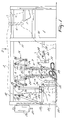
- Figure 1 is a side view of a milk box 1, which is provided near one longitudinal side with an entrance door 2, via which the animal 3 can enter the milk box 1, as well as an exit door 4, via which the animal 3 can leave the milk box 1.
- a feed trough 5 in which fodder, such as concentrate, can be supplied to the animal 3 by means of a (non-shown) concentrate metering system.
- the entrance door 2 and the exit door 4 can be operated automatically by a (non-shown) computer.
- the animal 3 further wears a collar 6 to which there is fitted a transponder cooperating with a (non-shown) animal identification system and by means of which the animal which is present in the milk box can be identified.
- the milk box 1 is further provided with a milking robot 7 for automatically connecting teat cups 8 to the teats of the animal 3 to be milked respectively disconnecting same therefrom.
- the milking robot 7 comprises two robot arms 9 which are fitted near a longitudinal side to an upper beam 10 of a frame 11 of the milk box 1 ( Figure 1).
- the milking robot 7 further comprises two other robot arms 12 which are fitted to an upper beam 13 of the exit door 4.
- Each of the robot arms 9, 12 comprises a first parallelogram construction 14 which is mounted to the relevant upper beam 10, 13.
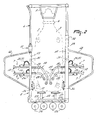
- the first parallelogram construction 14 is located in a plane extending in the longitudinal direction of the milk box 1 ( Figure 2).
- a second parallelogram construction 15 is disposed by means of a lug 16 ( Figure 3).
- a third parallelogram construction 17 is fitted to the second parallelogram construction 15.
- the second parallelogram construction 15 and the third parallelogram construction 17 are located in a plane enclosing an angle of approximately 90° with the plane in which the first parallelogram construction 14 is located.
- a teat cup carrier 18 carrying at its end the teat cup 8.
- the teat cup carrier 18 comprises a first portion 19 which is located in the same plane as the second and third parallelogram constructions 15, 17, and a second portion 20 which is contiguous to the first portion 19 and extends obliquely rearwards and towards the centre of the milk box 1.
- the first portion 19 and the second portion 20 of the teat cup carrier 18 enclose an angle of approximately 45° with each other ( Figure 1).
- the foremost teat cup carriers 18 additionally comprise a third portion 42 which is contiguous to the second portion 20, which third portion 42 extends in the longitudinal direction of the milk box 1 and passes to beyond the rearmost teat cups 8.
- the first, second and third portions 19, 20 and 42 of the teat cup carrier 18 are hollow. In the cavities of the teat cup carrier 18 there are disposed a milk tube 21 and a pulsation tube 22.
- the first, second and third parallelogram constructions 14, 15 and 17 are each provided with operating means 23 for controlling said parallelogram constructions.
- the teat cup carrier 18 can be moved both in a plane in the longitudinal direction of the milk box 1 and in a plane that is approximately perpendicular thereto.
- the operating means 23 comprise servo-pneumatic cylinders 24. These servo-pneumatic cylinders 24 are capable of being activated by means of a computer and always give a feedback signal regarding the position assumed by the piston of the cylinder. In this manner it is always possible to check accurately how the teat cups 8 are positioned relative to the milk box 1.
- the robot arms 9 are further provided with overload means which prevent a robot arm 9 from being damaged when the latter is overloaded, e.g. because of the fact that the animal 3 puts a leg on the robot arm 9.
- the overload means comprise one or more (non-shown) adjustable overpressure valves in the pneumatic line of the servo-pneumatic cylinders 24. It is further also possible to apply, instead of an overload valve, pressure sensors which are disposed on both sides of the piston of the cylinder and which, when a specific pressure has been exceeded at one side, supply a signal, whereafter the cylinder is energized in order that the pressure at that side decreases to below the threshold value.
- milk collecting elements 26 are fitted to a crossbeam 25 of the frame 11.
- Each of the milk collecting elements 26 comprises near its upper end a connection for the milk tube 21 of a relevant teat cup 8.
- the milk collecting elements 26 are provided at their lower sides with a discharge line 27 which is in contact with (non-shown) switch means for discharging milk to different storage tanks.
- the milk collecting elements 26 are designed as milk glasses.
- milk quality sensors for establishing the milk quality in the relevant milk collecting element 26.
- the milk quality sensors comprise conductivity sensors as well as sensors for determining the fat and protein content and the germ count of the milk.
- the implement is furthermore provided with detectors 28 for determining the position of the teats of an animal to be milked.
- the detectors 28 are disposed on both longitudinal sides of the milk box 1.
- One detector 28 is connected with the entrance door 2 of the milk box, the arrangement being such that when the animal 3 enters the milk box 1, this detector does not form an obstacle.
- the other detector 28 is connected with a stand 30 of the frame 11 by means of a horizontal beam 29.
- Each of the detectors 28 comprises a laser 31 which is pivoted in a recoprocating manner about an approximately vertical axis by means of a stepper motor 32.
- the implement for automatically milking animals further comprises animal-following means 33 with the aid of which the position of the animal 3, or at least a part of the animal 3, relative to the milk box can be determined and, on the basis of this position, using a (non-shown) computer, both during and after connection of the teat cups 8 to the teats of the animal 3 to be milked, the operating means 23 of the robot arms 9 can be post-controlled in order that the teat cups 8, during moving of the animal 3 in the milk box 1, continue to follow the movements of the animal 3.
- the animal-following means 33 comprise four mechanical sensors 34 of which one is located against each flank of the animal 3 when the latter is present in the milk box 1 while the two other ones push against its rear side when the animal is present in the milk box 1.
- the mechanical sensors 34 comprise a hingeable arm construction 35 whose lower side is connected with the frame 11 of the milk box 1 so as to be hingeable about a horizontal axis 36. At the other end of the hingeable arm construction 35 there is disposed a stop 37 which is pivotable about a further horizontal axis 38.
- the stop 37 is washer-shaped.
- a registration means 39 is connected with the horizontal axis 36 of the hingeable arm construction 35, which registration means 39 establishes the angle rotation of the horizontal axis 36 and converts it into an electronic signal which is supplied to a (non-shown) computer and which can be converted into a control signal for the operating means 23 of the parallelogram constructions.
- the registration means 39 comprise stepper motors. Instead of stepper motors, e.g. potentiometers may be used as well.
- the stepper motor 39 is computer-controlled thus making it possible to pivot the hingeable arm constructions 35 away, so that they do not form an obstacle for the animal when the latter enters the milk box 1.
- the stepper motors 39 are energized, so that the stops 37 will be positioned against the animal by a predetermined and adjustable force.
- the light pressure exerted on the animal under the influence of the stepper motors 39 ensures that the stops 37 remain in contact with the animal's body, so that each movement of the animal 3 in the milk box 1 can be followed.
- FIG. 5 shows a second embodiment according to the invention comprising the same elements as the preceding embodiment but in which the milking robot is particularly suitable for milking small animals, such as sheep and goats, or other animals, such as elks, etc.
- the milking robot is particularly suitable for milking small animals, such as sheep and goats, or other animals, such as elks, etc.
- the teat cups 41 have a length of approximately 12 cm. However, it will be obvious that the length of the teat cups depends on the kind of animals to be milked.
- FIG 6 shows a third embodiment according to the invention, which also comprises the same elements as the first embodiment, but in which the teat cup carriers 18 are fastened to the third parallelogram construction 17 at an angle of approximately 30° obliquely downwards. Furthermore the teat cups 8 are fitted near their upper ends to the teat cup carriers 18. Due to the fact that the teat cup carriers 18 extend obliquely downwards, at an angle which may also be different from 30°, there is created relatively much freedom on the bottom under the carriers 18, so that it will be more difficult for the animal to kick on or against the teat cup carriers 18.
- the implement according to the invention functions as follows and has the following advantages:
- a further advantage of the implement according to the invention is that the four teat cups can be connected collectively in one movement to the teats of an animal to be milked.
Landscapes
- Life Sciences & Earth Sciences (AREA)
- Animal Husbandry (AREA)
- Environmental Sciences (AREA)
- External Artificial Organs (AREA)
- Housing For Livestock And Birds (AREA)
- Manipulator (AREA)
Applications Claiming Priority (3)
| Application Number | Priority Date | Filing Date | Title |
|---|---|---|---|
| NL1006171 | 1997-05-30 | ||
| NL1006171A NL1006171C2 (nl) | 1997-05-30 | 1997-05-30 | Constructie met een inrichting voor het automatisch melken van dieren. |
| EP19980201646 EP0880888B1 (de) | 1997-05-30 | 1998-05-18 | Vorrichtung zum automatischen Melken von Tieren |
Related Parent Applications (1)
| Application Number | Title | Priority Date | Filing Date |
|---|---|---|---|
| EP19980201646 Division EP0880888B1 (de) | 1997-05-30 | 1998-05-18 | Vorrichtung zum automatischen Melken von Tieren |
Publications (2)
| Publication Number | Publication Date |
|---|---|
| EP1208742A2 true EP1208742A2 (de) | 2002-05-29 |
| EP1208742A3 EP1208742A3 (de) | 2003-01-15 |
Family
ID=19765057
Family Applications (2)
| Application Number | Title | Priority Date | Filing Date |
|---|---|---|---|
| EP02075593A Withdrawn EP1208742A3 (de) | 1997-05-30 | 1998-05-18 | Vorrichtung zum automatischen Melken von Tieren |
| EP19980201646 Expired - Lifetime EP0880888B1 (de) | 1997-05-30 | 1998-05-18 | Vorrichtung zum automatischen Melken von Tieren |
Family Applications After (1)
| Application Number | Title | Priority Date | Filing Date |
|---|---|---|---|
| EP19980201646 Expired - Lifetime EP0880888B1 (de) | 1997-05-30 | 1998-05-18 | Vorrichtung zum automatischen Melken von Tieren |
Country Status (4)
| Country | Link |
|---|---|
| EP (2) | EP1208742A3 (de) |
| DE (1) | DE69807574T2 (de) |
| DK (1) | DK0880888T3 (de) |
| NL (1) | NL1006171C2 (de) |
Cited By (3)
| Publication number | Priority date | Publication date | Assignee | Title |
|---|---|---|---|---|
| WO2004032608A1 (en) * | 2002-10-11 | 2004-04-22 | Delaval Holding Ab | A milking plant |
| WO2005094566A2 (de) * | 2004-03-23 | 2005-10-13 | Maier Jakob Jr | Haltevorrichtung für melkbecher und aktuatorvorrichtung zum erzeugen einer bewegung eines melkgeschirrs |
| WO2007045489A1 (de) * | 2005-10-20 | 2007-04-26 | Gea Westfaliasurge Gmbh | Melkvorrichtung und melkverfahren |
Families Citing this family (7)
| Publication number | Priority date | Publication date | Assignee | Title |
|---|---|---|---|---|
| NL1018633C2 (nl) † | 2001-07-25 | 2003-01-28 | Lely Entpr Ag | Werkwijze en inrichting voor het automatisch melken van een melkdier. |
| SE0201380D0 (sv) * | 2002-05-07 | 2002-05-07 | Delaval Holding Ab | Automatic milk separation |
| DE10351549A1 (de) * | 2003-11-03 | 2005-06-02 | Westfaliasurge Gmbh | Einheit zur Lageänderung einer Leitung, insbesondere einer Milchleitung |
| SE0401513D0 (sv) | 2004-06-14 | 2004-06-14 | Delaval Holding Ab | Rotary parlour with delivery lines |
| NZ566631A (en) | 2008-03-11 | 2011-04-29 | Scott Milktech Ltd | A robotic milking system and a method of attaching milking cups |
| AU2009224053B2 (en) | 2008-03-11 | 2014-11-27 | Scott Technology Nz Limited | A robot milking arm and a method of attaching milking cups |
| NL2019313B1 (nl) | 2017-07-21 | 2019-02-01 | Lely Patent Nv | Melkrobotsysteem met selecteerbare compliantie |
Citations (4)
| Publication number | Priority date | Publication date | Assignee | Title |
|---|---|---|---|---|
| EP0541517A2 (de) * | 1985-01-28 | 1993-05-12 | C. van der Lely N.V. | Vorrichtung zum Melken von Tieren |
| WO1996011568A2 (en) * | 1994-10-12 | 1996-04-25 | Maasland N.V. | A method of and an implement for automatically milking animals, such as cows |
| EP0717926A1 (de) * | 1994-12-20 | 1996-06-26 | Maasland N.V. | Vorrichtung zum automatischen Melken von Tieren, wie zum Beispiel Kühen |
| WO1997018701A2 (en) * | 1995-11-24 | 1997-05-29 | Maasland N.V. | An implement for milking animals |
Family Cites Families (5)
| Publication number | Priority date | Publication date | Assignee | Title |
|---|---|---|---|---|
| NL8502434A (nl) * | 1985-09-04 | 1987-04-01 | Multinorm Bv | Melkinrichting. |
| ATE68935T1 (de) * | 1986-08-27 | 1991-11-15 | Lely Nv C Van Der | Geraet zum melken von tieren. |
| GB8900084D0 (en) * | 1989-01-04 | 1989-03-01 | British Res Agricult Eng | Milking |
| NL9200051A (nl) * | 1992-01-13 | 1993-08-02 | Prolion Bv | Automatische melkinrichting. |
| NL9401114A (nl) * | 1994-07-04 | 1996-02-01 | Maasland Nv | Constructie met een inrichting voor het automatisch melken van dieren. |
-
1997
- 1997-05-30 NL NL1006171A patent/NL1006171C2/nl not_active IP Right Cessation
-
1998
- 1998-05-18 DE DE1998607574 patent/DE69807574T2/de not_active Expired - Lifetime
- 1998-05-18 EP EP02075593A patent/EP1208742A3/de not_active Withdrawn
- 1998-05-18 DK DK98201646T patent/DK0880888T3/da active
- 1998-05-18 EP EP19980201646 patent/EP0880888B1/de not_active Expired - Lifetime
Patent Citations (4)
| Publication number | Priority date | Publication date | Assignee | Title |
|---|---|---|---|---|
| EP0541517A2 (de) * | 1985-01-28 | 1993-05-12 | C. van der Lely N.V. | Vorrichtung zum Melken von Tieren |
| WO1996011568A2 (en) * | 1994-10-12 | 1996-04-25 | Maasland N.V. | A method of and an implement for automatically milking animals, such as cows |
| EP0717926A1 (de) * | 1994-12-20 | 1996-06-26 | Maasland N.V. | Vorrichtung zum automatischen Melken von Tieren, wie zum Beispiel Kühen |
| WO1997018701A2 (en) * | 1995-11-24 | 1997-05-29 | Maasland N.V. | An implement for milking animals |
Cited By (5)
| Publication number | Priority date | Publication date | Assignee | Title |
|---|---|---|---|---|
| WO2004032608A1 (en) * | 2002-10-11 | 2004-04-22 | Delaval Holding Ab | A milking plant |
| WO2005094566A2 (de) * | 2004-03-23 | 2005-10-13 | Maier Jakob Jr | Haltevorrichtung für melkbecher und aktuatorvorrichtung zum erzeugen einer bewegung eines melkgeschirrs |
| WO2005094566A3 (de) * | 2004-03-23 | 2005-11-24 | Jakob Maier Jr | Haltevorrichtung für melkbecher und aktuatorvorrichtung zum erzeugen einer bewegung eines melkgeschirrs |
| US8925484B2 (en) | 2004-03-23 | 2015-01-06 | Jakob Maier, Jr. | Retaining device for teat cups and actuator for inciting a movement of a teat cup cluster |
| WO2007045489A1 (de) * | 2005-10-20 | 2007-04-26 | Gea Westfaliasurge Gmbh | Melkvorrichtung und melkverfahren |
Also Published As
| Publication number | Publication date |
|---|---|
| NL1006171C2 (nl) | 1998-12-01 |
| EP0880888A2 (de) | 1998-12-02 |
| EP0880888A3 (de) | 1999-01-27 |
| EP0880888B1 (de) | 2002-09-04 |
| DK0880888T3 (da) | 2003-01-06 |
| DE69807574D1 (de) | 2002-10-10 |
| EP1208742A3 (de) | 2003-01-15 |
| DE69807574T2 (de) | 2003-08-07 |
Similar Documents
| Publication | Publication Date | Title |
|---|---|---|
| EP0188303B1 (de) | Gerät und Verfahren zum Melken von Tieren, wie z.B. Kühen | |
| EP0320496B2 (de) | Gerät zum automatischen Melken von Tieren | |
| EP0726703B1 (de) | Vorrichtung und verfahren zum melken von tieren | |
| EP0551960B1 (de) | Vorrichtung zum automatischen Melken von Tieren | |
| EP1559313B1 (de) | Verfahren und Vorrichtung zum automatischen Verbinden von Melkbechern zu der Zitze eines zu melkenden Tieres | |
| JPH08275687A (ja) | 乳牛のような動物の自動搾乳手段を位置決めする方法並びにこの方法を実施する装置 | |
| EP0880888B1 (de) | Vorrichtung zum automatischen Melken von Tieren | |
| EP0647390B1 (de) | Konstruktion zum automatischen Melken von Tieren | |
| EP0322404A2 (de) | Gerät zum Melken von Tieren, wie z.B. Kühen | |
| EP0728411B1 (de) | Vorrichtung zum Melken von Tieren | |
| CA2388923C (en) | Means for improved milking | |
| EP0647391B1 (de) | Konstruktion zum automatischen Melken von Tieren | |
| EP1172029B1 (de) | Konstruktion zum automatischen Melken von Tieren | |
| WO1999031970A1 (en) | An animal related apparatus | |
| EP0647392B1 (de) | Konstruktion zum automatischen Melken von Tieren | |
| EP0634095B1 (de) | Vorrichtung zum automatischen Melken von Tieren | |
| EP1252817A2 (de) | Konstruktion mit einem Gerät zum automatischen Melken von Tieren |
Legal Events
| Date | Code | Title | Description |
|---|---|---|---|
| PUAI | Public reference made under article 153(3) epc to a published international application that has entered the european phase |
Free format text: ORIGINAL CODE: 0009012 |
|
| AC | Divisional application: reference to earlier application |
Ref document number: 880888 Country of ref document: EP |
|
| AK | Designated contracting states |
Kind code of ref document: A2 Designated state(s): DE DK FR GB IT NL SE |
|
| PUAL | Search report despatched |
Free format text: ORIGINAL CODE: 0009013 |
|
| AK | Designated contracting states |
Kind code of ref document: A3 Designated state(s): DE DK FR GB IT NL SE |
|
| 17P | Request for examination filed |
Effective date: 20030604 |
|
| 17Q | First examination report despatched |
Effective date: 20030708 |
|
| AKX | Designation fees paid |
Designated state(s): DE DK FR GB IT NL SE |
|
| STAA | Information on the status of an ep patent application or granted ep patent |
Free format text: STATUS: THE APPLICATION IS DEEMED TO BE WITHDRAWN |
|
| 18D | Application deemed to be withdrawn |
Effective date: 20031119 |