EP0318359A1 - Vorrichtung zum Ausspreizen der Leitflügel eines Geschosses - Google Patents
Vorrichtung zum Ausspreizen der Leitflügel eines Geschosses Download PDFInfo
- Publication number
- EP0318359A1 EP0318359A1 EP88402880A EP88402880A EP0318359A1 EP 0318359 A1 EP0318359 A1 EP 0318359A1 EP 88402880 A EP88402880 A EP 88402880A EP 88402880 A EP88402880 A EP 88402880A EP 0318359 A1 EP0318359 A1 EP 0318359A1
- Authority
- EP
- European Patent Office
- Prior art keywords
- fin
- projectile
- deployment
- axis
- deployed position
- Prior art date
- Legal status (The legal status is an assumption and is not a legal conclusion. Google has not performed a legal analysis and makes no representation as to the accuracy of the status listed.)
- Granted
Links
Images
Classifications
-
- F—MECHANICAL ENGINEERING; LIGHTING; HEATING; WEAPONS; BLASTING
- F42—AMMUNITION; BLASTING
- F42B—EXPLOSIVE CHARGES, e.g. FOR BLASTING, FIREWORKS, AMMUNITION
- F42B10/00—Means for influencing, e.g. improving, the aerodynamic properties of projectiles or missiles; Arrangements on projectiles or missiles for stabilising, steering, range-reducing, range-increasing or fall-retarding
- F42B10/02—Stabilising arrangements
- F42B10/14—Stabilising arrangements using fins spread or deployed after launch, e.g. after leaving the barrel
Definitions
- the field of the invention is that of deployment devices for projectile fins, and more particularly for orientable fins, that is to say which can pivot in the depolated position under the action of a pilot motor around an axis. substantially perpendicular to the axis of the projectile.
- the deployable fins can only play a stabilizing role for a projectile animated by a slow or zero rotation movement, or also a guiding role, similar to that of the control surfaces for an airplane; in the latter case, they are controlled by a motor, itself piloted by an electronic assembly, they then make it possible to modify the trajectory of the projectile during its flight and therefore to correct possible aiming errors, or else to orient automatically, after detection of a target, the projectile towards it.
- the fins begin by presenting their largest surface facing the aerodynamic flow; the leading edge of the fins, the surface of which is smaller, being oriented in the direction of this flow only at the end of the deployment movement. It follows a braking of the projectile and a risk of destabilization all the more important as the asymmetries at the level of the movements of opening of the fins will be amplified by the importance of the forces which are exerted on them. The risk of destabilization will be even more critical in the case where the projectile is initially gyro-stabilized and where the deployment of the fins must allow it to adopt a regime stabilized by empennage.
- the invention applied to fins which have to provide a guiding function, also provides a means making it possible to completely control their opening movement as well as the instant of triggering of the latter, without however requiring an additional locking device.
- the subject of the invention is a device for deploying a projectile fin between a carrying position, in which its plane is substantially parallel to the axis of the projectile, and a deployed position, the fin being made integral with the projectile by an articulation, device characterized in that the articulation is such that the deployment movement comprises at least two phases: a first in which the fin passes from the carrying position to a semi-deployed position, this passage being obtained by a rotation along a first axis which is perpendicular to the plane of the fin when the latter is in the position of takeout and a second in which the fin passes from the semi-deployed position to the deployed position, by a rotation along a second axis which is parallel to the plane of the fin.
- the fin is moved by an actuator during all or part of the first phase of the deployment movement, and it is immobilized relative to the projectile by a locking means when it is in its carrying position.
- the fin in the deployed position can pivot around the first axis under the action of a pilot motor, and this constitutes the actuator and / or the locking means .
- the fin is secured to a support, itself immobilized relative to the inner ring of a bearing, the outer ring of this bearing being immobilized relative to the projectile, and on the other apart the motor is immobilized relative to the projectile and controls the rotation of the support by means of a coupling joint.
- the fin may be moved by aerodynamic forces during the second phase of the deployment movement; in this case it may carry a pin, circulating during the first phase of the deployment movement in a circular groove immobilized relative to the projectile, the second phase intervening during the passage of the pin before a clearance of this groove.
- the support will carry a lock immobilizing the fin relative to the latter in the deployed position.
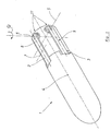
- a projectile 1 has at its rear part four fins 2, (shown schematically in the form of parallelepipeds to simplify the description), intended to provide both a stabilizing function and a guiding function; these fins are made integral with the projectile by joints 11, which will be described in detail below.
- the projectile is fired by a weapon, not shown, and is gyrostabilized during a first part of its trajectory, it therefore comprises known means and not represented here (such as a belt) of a nature to drive it in rotation during its journey to l inside the weapon.
- This belt may be integral with the projectile itself or with a stationary cylindrical element relative to the projectile, and released on trajectory by pyrotechnic means (see for example patent W081 / 00908).
- the fins 2 are shown in Figure 1 in the carrying position. They are immobilized relative to the projectile by a blocking means which will be described later.
- the plane of the fin which is defined by an axis 8, materializing the main direction thereof, and an axis 7 orthogonal to the previous one, is substantially parallel to the axis 4 of the projectile.
- This position is analogous to the carrying position described in patent US4664339.
- the front end of each fin comes into a housing 3 in the body of the projectile 1.
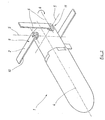
- Figure 2 shows the projectile with its fins without a semi-deployed position.
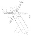
- Figure 3 shows the projectile with the fins fully deployed.
- the transition from the semi-deployed position to the deployed position (second phase of the deployment movement) is obtained by a rotation in the ⁇ direction, of each fin around a second axis 6, which is parallel to the plane of the 'fin.
- the forces undergone by the fins are also reduced in substantially the same ratio, which makes it possible to reduce the mass of the fins in favor of the payload of the projectile, and to reduce shocks and destabilizing asymmetries.
- each fin being greater in direction 7 than in the direction normal to the plane of the fin (inertia ratio of the order of 60), the latter are less sensitive to the bending deformations induced by the aerodynamic forces.
- This increase in the rigidity of the fins results in an increase in their natural vibration frequencies, which, in combination with the notable reduction in the forces to which they are subjected, makes it possible to guarantee a regular deployment movement of each fin, which reduces the risks destabilization of the projectile.
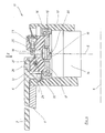
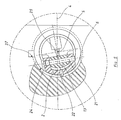
- FIGS 4 and 5 show in detail the joint 11, the locking means and the actuator, which allow to obtain the two phases of the deployment movement described above, in this particular embodiment of the device according to invention.
- Each fin 2 is made integral with a support 13 by means of a pivot 21 which materializes the second axis 6.
- the mounting of the fin on the support is of the clevis-tenon type, the fin having one end constituting a clevis and the post being formed by the support 13. This type of arrangement made it possible to obtain better guidance of the fin during its deployment movement.
- the fin is here shown in the carrying position with its plane parallel to the axis 4 of the projectile 1.
- the support 13 is immobilized relative to the inner ring 16 of a bearing with two rows of angular contact balls.
- the outer ring 15 of this bearing is immobilized by threading relative to a housing 12, itself secured to the projectile 1.
- the bearing-bearing assembly thus constitutes the joint 11.
- a motor 14, here an electric geared motor, is also immobilized relative to the box 12; in this particular embodiment, it is linked in translation to the housing by means of a shoulder of the latter and of the outer ring 15 of the bearing, and in rotation by pins not shown.
- the motor 14 carries, on the upper part of its axis, a groove 20, and the support 13 a groove 19, these two grooves constitute, with an intermediate part 18, a seal of coupling, preferably a constant velocity joint, such as an Oldham joint here, which allows the motor 14 to drive the support 13, carrying the fin 2, in rotation around the first axis 5.
- the coupling joint makes it possible to tolerate poor axial alignment when mounting the support and the motor, but it also makes it possible to isolate the latter from the vibrations which the fin could impart to it.
- the bearing also makes it possible to isolate the engine from the aerodynamic forces which the fin will therefore transmit directly to the projectile 1, via the support and the bearing.
- the fin carries a pin 22, one end of which is housed in a circular groove 24 carried by the housing. This circular groove ends with a clearance 27 (see FIG. 5), the usefulness of which will be specified below.
- the support 13 also carries a lock 23, which is constituted by a finger 25, sliding against the action of a return spring, and which is intended to come into a housing 26 carried by the fin 2, this for the purpose to lock it in the deployed position at the end of the second phase of the deployment movement.
- an encoder 17, of known type, and integral with the support 13, will make it possible to give an electronic control assembly, not shown, the information of angular position of the fin 2 relative to the first axis 5.
- the motor the main function of which is to guide the projectile by pivoting the deployed fin around the first axis 5
- the actuator which causes the first phase of the deployment movement of the fin: its passage from the carrying position to the semi-deployed position.
- the motor due to the irreversibility of the mechanical reducer which it comprises, also plays the role of means for blocking the fin in the carrying position.
- the start of the opening is completely controlled and corresponds to the control of the motors; speeds and positions of the fins can be controlled by an electronic device, known per se, which will play individually on the control voltages of the different motors as a function of the information given by the encoders.
- the control of the motors therefore makes it possible to accomplish the first phase of the deployment movement, which as has been seen previously will make it possible to obtain progressive braking of the rotation of the projectile; (but it is also possible to use other types of vanes of known type, such as those described in patent W081 / 00908, to cause braking in rotation, the deployment of the guide vanes then being controlled only when the speed of rotation has fallen below a certain value, of the order of 20 to 30 revolutions / second); when the fins are in the position of FIG. 2, the pin 22, which has circulated during the first phase of the deployment movement in the groove 24 and has thus maintained the fin in the plane defined by the axes 7 and 8, is then opposite the clearance 27.
- the aerodynamic forces exerted on the fin are sufficient to rotate it around the second axis 6 and therefore to make it accomplish the second phase of the deployment movement, just until the locking of the fin; the engine then fulfilling its guiding role by pivoting the deployed fin around the first axis.
- motors can be envisaged to fulfill both the function of actuator of the deployment movement of the fin, and the function of piloting the projectile; such as a pneumatic motor, powered by a gas reserve or else by a gas generator with pyrotechnic initiation.
Landscapes
- Physics & Mathematics (AREA)
- Fluid Mechanics (AREA)
- Engineering & Computer Science (AREA)
- General Engineering & Computer Science (AREA)
- Toys (AREA)
Applications Claiming Priority (2)
| Application Number | Priority Date | Filing Date | Title |
|---|---|---|---|
| FR8716389 | 1987-11-26 | ||
| FR8716389A FR2623898B1 (fr) | 1987-11-26 | 1987-11-26 | Dispositif de deploiement d'une ailette de projectile |
Publications (2)
| Publication Number | Publication Date |
|---|---|
| EP0318359A1 true EP0318359A1 (de) | 1989-05-31 |
| EP0318359B1 EP0318359B1 (de) | 1992-06-17 |
Family
ID=9357188
Family Applications (1)
| Application Number | Title | Priority Date | Filing Date |
|---|---|---|---|
| EP88402880A Expired - Lifetime EP0318359B1 (de) | 1987-11-26 | 1988-11-16 | Vorrichtung zum Ausspreizen der Leitflügel eines Geschosses |
Country Status (7)
| Country | Link |
|---|---|
| US (1) | US5108051A (de) |
| EP (1) | EP0318359B1 (de) |
| CA (1) | CA1333027C (de) |
| DE (1) | DE3872181T2 (de) |
| ES (1) | ES2032045T3 (de) |
| FR (1) | FR2623898B1 (de) |
| TR (1) | TR23598A (de) |
Cited By (9)
| Publication number | Priority date | Publication date | Assignee | Title |
|---|---|---|---|---|
| GB2231942A (en) * | 1989-05-12 | 1990-11-28 | Diehl Gmbh & Co | Submunition flying body |
| FR2655720A1 (fr) * | 1989-12-08 | 1991-06-14 | Thomson Brandt Armements | Aile galbee deployable pour engin volant. |
| EP0568487A1 (de) * | 1992-04-30 | 1993-11-03 | State of Israel Ministry of Defence Raphael Armament Development Authority | Klappleitwerk zum Entfalten bei der Beschleunigung |
| EP0572803A3 (en) * | 1992-05-08 | 1994-05-11 | Rockwell International Corp | Self propelled underwater device with steerable fin stabilizer |
| WO2009051865A1 (en) * | 2007-10-18 | 2009-04-23 | Hr Textron Inc. | Locking assembly for rotary shafts |
| WO2009107126A1 (en) * | 2008-02-26 | 2009-09-03 | Elbit Systems Ltd. | Foldable and deployable panel |
| FR3039265A1 (fr) * | 2015-07-21 | 2017-01-27 | Dcns | Projectile a ailettes de stabilisation de type couteau |
| FR3054030A1 (fr) * | 2016-07-18 | 2018-01-19 | Nexter Munitions | Projectile comprenant un dispositif de deploiement d'une voilure ou ailette |
| CN114777574A (zh) * | 2022-04-02 | 2022-07-22 | 合肥工业大学 | 一种折叠弹翼装置 |
Families Citing this family (33)
| Publication number | Priority date | Publication date | Assignee | Title |
|---|---|---|---|---|
| FR2674619B1 (fr) * | 1991-03-26 | 1993-07-09 | Sagem | Dispositif de deplacement d'une ailette d'un projectile. |
| DE4119613C2 (de) * | 1991-06-14 | 1997-03-27 | Diehl Gmbh & Co | Flugkörper mit ausklappbaren Leiteinrichtungen |
| US5582364A (en) * | 1991-11-07 | 1996-12-10 | Hughes Missile Systems Company | Flyable folding fin |
| IL107844A (en) * | 1993-12-02 | 1996-06-18 | Ministry Of Defence Armaments | Flying object control system |
| US6168111B1 (en) | 1997-03-03 | 2001-01-02 | The United States Of America As Represented By The Secretary Of The Army | Fold-out fin |
| US6126109A (en) * | 1997-04-11 | 2000-10-03 | Raytheon Company | Unlocking tail fin assembly for guided projectiles |
| US6186443B1 (en) | 1998-06-25 | 2001-02-13 | International Dynamics Corporation | Airborne vehicle having deployable wing and control surface |
| RU2148778C1 (ru) * | 1999-02-04 | 2000-05-10 | Государственное научно-производственное предприятие "Сплав" | Ракета, запускаемая из трубчатой направляющей |
| US6928400B2 (en) * | 2001-10-02 | 2005-08-09 | Raytheon Company | Method for designing a deployment mechanism |
| US20040041059A1 (en) * | 2002-09-03 | 2004-03-04 | Kennedy Kevin D. | Device for projectile control |
| US6695252B1 (en) * | 2002-09-18 | 2004-02-24 | Raytheon Company | Deployable fin projectile with outflow device |
| FR2846080B1 (fr) | 2002-10-17 | 2007-05-25 | Giat Ind Sa | Dispositif de deploiement et d'entrainement de gouvernes de projectile |
| FR2846079B1 (fr) | 2002-10-17 | 2006-08-18 | Giat Ind Sa | Dispositif de verrouillage/deverrouillage et d'entrainement de gouvernes de projectile |
| AU2002346422A1 (en) * | 2002-11-18 | 2004-06-15 | Raytheon Company | Method for designing a fin deployment mechanism |
| US6834828B1 (en) | 2003-09-23 | 2004-12-28 | The United States Of America As Represented By The Secretary Of The Navy | Fin deployment system |
| US7185846B1 (en) * | 2006-03-06 | 2007-03-06 | The United States Of America As Represented By The Secretary Of The Army | Asymmetrical control surface system for tube-launched air vehicles |
| FR2911954B1 (fr) | 2007-01-31 | 2009-04-24 | Nexter Munitions Sa | Dispositif de pilotage d'une munition a gouvernes deployables |
| US7856929B2 (en) | 2007-06-29 | 2010-12-28 | Taser International, Inc. | Systems and methods for deploying an electrode using torsion |
| KR102105282B1 (ko) | 2009-02-02 | 2020-04-28 | 에어로바이론먼트, 인크. | 멀티모드 무인 항공기 |
| US7997205B2 (en) * | 2009-05-08 | 2011-08-16 | Raytheon Company | Base drag reduction fairing |
| CN105151275B (zh) * | 2009-09-09 | 2017-05-31 | 威罗门飞行公司 | 升降副翼控制系统 |
| KR102049708B1 (ko) | 2009-09-09 | 2020-01-08 | 에어로바이론먼트, 인크. | 휴대용 rf 투명 발사관을 구비한 원격 조종 무인 항공기 포성 억제 발사장치를 위한 시스템 및 장치 |
| US9453531B2 (en) | 2013-08-26 | 2016-09-27 | Roller Bearing Company Of America, Inc. | Integrated bearing assemblies for guided attack rockets |
| EP4365088A3 (de) | 2014-03-13 | 2024-12-04 | Endurant Systems LLC | Batteriesteigerung für uav-verbrennungsmotoren |
| IL241201B (en) * | 2015-09-06 | 2019-11-28 | Uvision Air Ltd | Folding wings for an unmanned aerial vehicle |
| US9821909B2 (en) | 2016-04-05 | 2017-11-21 | Swift Engineering, Inc. | Rotating wing assemblies for tailsitter aircraft |
| CN106352746B (zh) * | 2016-10-18 | 2018-03-09 | 湖北航天技术研究院总体设计所 | 一种折叠翼自动同步解锁驱动装置 |
| CN107776870A (zh) * | 2017-10-27 | 2018-03-09 | 成都云鼎智控科技有限公司 | 一种机翼折叠锁定组件及无人机 |
| CN108100217A (zh) * | 2017-12-29 | 2018-06-01 | 北京华信宇航科技有限公司 | 一种基于x翼布局的无人飞行器 |
| US11300390B1 (en) * | 2018-03-05 | 2022-04-12 | Dynamic Structures And Materials, Llc | Control surface deployment apparatus and method of use |
| US20200079492A1 (en) | 2018-09-11 | 2020-03-12 | Swift Engineering, Inc. | Systems and methods for aerodynamic deployment of wing structures |
| CN112046731B (zh) * | 2020-08-31 | 2022-06-10 | 中国电子科技集团公司第四十一研究所 | 一种x翼无人机尾翼折叠展开传动机构 |
| CN113108652B (zh) * | 2021-04-13 | 2022-09-27 | 哈尔滨工程大学 | 一种导弹舵面旋转折叠收放结构 |
Citations (5)
| Publication number | Priority date | Publication date | Assignee | Title |
|---|---|---|---|---|
| FR1270328A (fr) * | 1960-10-12 | 1961-08-25 | Ml Aviation Co Ltd | Projectile propulsé par roquette |
| US3643599A (en) * | 1968-07-22 | 1972-02-22 | Us Navy | Retractable stabilizer fins and drag brakes for missiles |
| FR2100377A5 (de) * | 1970-07-10 | 1972-03-17 | Sarmac Sa | |
| FR2539503A1 (fr) * | 1983-01-14 | 1984-07-20 | Luchaire Sa | Dispositif pour le deploiement automatique des ailettes d'un empennage destine a la stabilisation d'un engin lance par piston |
| US4588146A (en) * | 1984-03-29 | 1986-05-13 | The United States Of America As Represented By The Secretary Of The Army | Biaxial folding lever wing |
Family Cites Families (11)
| Publication number | Priority date | Publication date | Assignee | Title |
|---|---|---|---|---|
| US2402468A (en) * | 1942-11-02 | 1946-06-18 | Earnest W Harrison | Aerial and land vehicle |
| US2572421A (en) * | 1947-09-20 | 1951-10-23 | Jr Edmund Abel | Aircraft folding wing construction |
| US3063375A (en) * | 1960-05-19 | 1962-11-13 | Wilbur W Hawley | Folding fin |
| US3098445A (en) * | 1960-06-27 | 1963-07-23 | Auradynamics Inc | Aerodynamically supported rocket |
| US3127838A (en) * | 1960-10-12 | 1964-04-07 | Bombrini Parodi Delfino Spa | Retractable blade tail unit for projectiles |
| AU524255B2 (en) * | 1978-12-29 | 1982-09-09 | Commonwealth Of Australia, The | Deployable wing |
| US4323208A (en) * | 1980-02-01 | 1982-04-06 | British Aerospace | Folding fins |
| GB2150092B (en) * | 1983-11-25 | 1987-07-22 | British Aerospace | Deployment and actuation mechanisms |
| US4592525A (en) * | 1985-02-07 | 1986-06-03 | The United States Of America As Represented By The Secretary Of The Army | Counter-rotating folding wings |
| FR2600618A1 (fr) * | 1986-06-27 | 1987-12-31 | Thomson Brandt Armements | Aile a deploiement multiple, et son application a un engin volant |
| US4869442A (en) * | 1988-09-02 | 1989-09-26 | Aerojet-General Corporation | Self-deploying airfoil |
-
1987
- 1987-11-26 FR FR8716389A patent/FR2623898B1/fr not_active Expired - Lifetime
-
1988
- 1988-11-16 ES ES198888402880T patent/ES2032045T3/es not_active Expired - Lifetime
- 1988-11-16 DE DE8888402880T patent/DE3872181T2/de not_active Expired - Lifetime
- 1988-11-16 EP EP88402880A patent/EP0318359B1/de not_active Expired - Lifetime
- 1988-11-22 US US07/274,904 patent/US5108051A/en not_active Expired - Lifetime
- 1988-11-23 TR TR846/88A patent/TR23598A/xx unknown
- 1988-11-25 CA CA000584112A patent/CA1333027C/fr not_active Expired - Fee Related
Patent Citations (5)
| Publication number | Priority date | Publication date | Assignee | Title |
|---|---|---|---|---|
| FR1270328A (fr) * | 1960-10-12 | 1961-08-25 | Ml Aviation Co Ltd | Projectile propulsé par roquette |
| US3643599A (en) * | 1968-07-22 | 1972-02-22 | Us Navy | Retractable stabilizer fins and drag brakes for missiles |
| FR2100377A5 (de) * | 1970-07-10 | 1972-03-17 | Sarmac Sa | |
| FR2539503A1 (fr) * | 1983-01-14 | 1984-07-20 | Luchaire Sa | Dispositif pour le deploiement automatique des ailettes d'un empennage destine a la stabilisation d'un engin lance par piston |
| US4588146A (en) * | 1984-03-29 | 1986-05-13 | The United States Of America As Represented By The Secretary Of The Army | Biaxial folding lever wing |
Cited By (17)
| Publication number | Priority date | Publication date | Assignee | Title |
|---|---|---|---|---|
| GB2231942A (en) * | 1989-05-12 | 1990-11-28 | Diehl Gmbh & Co | Submunition flying body |
| GB2231942B (en) * | 1989-05-12 | 1993-03-24 | Diehl Gmbh & Co | A submunition flying body |
| FR2655720A1 (fr) * | 1989-12-08 | 1991-06-14 | Thomson Brandt Armements | Aile galbee deployable pour engin volant. |
| EP0568487A1 (de) * | 1992-04-30 | 1993-11-03 | State of Israel Ministry of Defence Raphael Armament Development Authority | Klappleitwerk zum Entfalten bei der Beschleunigung |
| US5326049A (en) * | 1992-04-30 | 1994-07-05 | State Of Israel - Ministry Of Defense Rafael-Armament Development Authority | Device including a body having folded appendage to be deployed upon acceleration |
| EP0572803A3 (en) * | 1992-05-08 | 1994-05-11 | Rockwell International Corp | Self propelled underwater device with steerable fin stabilizer |
| US7700902B2 (en) | 2007-10-18 | 2010-04-20 | Hr Textron, Inc. | Locking assembly for rotary shafts |
| WO2009051865A1 (en) * | 2007-10-18 | 2009-04-23 | Hr Textron Inc. | Locking assembly for rotary shafts |
| JP2011501096A (ja) * | 2007-10-18 | 2011-01-06 | ウッドウォード エイチアールティー インコーポレイテッド | 回転軸用ロック機構 |
| WO2009107126A1 (en) * | 2008-02-26 | 2009-09-03 | Elbit Systems Ltd. | Foldable and deployable panel |
| US8324545B2 (en) | 2008-02-26 | 2012-12-04 | Elbit Systems Ltd. | Foldable and deployable panel |
| US8378278B2 (en) | 2008-02-26 | 2013-02-19 | Elbit Systems Ltd. | Foldable and deployable panel |
| FR3039265A1 (fr) * | 2015-07-21 | 2017-01-27 | Dcns | Projectile a ailettes de stabilisation de type couteau |
| FR3054030A1 (fr) * | 2016-07-18 | 2018-01-19 | Nexter Munitions | Projectile comprenant un dispositif de deploiement d'une voilure ou ailette |
| WO2018015367A1 (fr) | 2016-07-18 | 2018-01-25 | Nexter Munitions | Projectile comprenant un dispositif de déploiement d`une voilure ou ailette |
| US11079206B2 (en) | 2016-07-18 | 2021-08-03 | Nexter Munitions | Projectile comprising a device for deploying a wing or fin |
| CN114777574A (zh) * | 2022-04-02 | 2022-07-22 | 合肥工业大学 | 一种折叠弹翼装置 |
Also Published As
| Publication number | Publication date |
|---|---|
| US5108051A (en) | 1992-04-28 |
| FR2623898B1 (fr) | 1990-03-23 |
| CA1333027C (fr) | 1994-11-15 |
| DE3872181D1 (de) | 1992-07-23 |
| TR23598A (tr) | 1990-04-24 |
| EP0318359B1 (de) | 1992-06-17 |
| DE3872181T2 (de) | 1992-12-17 |
| ES2032045T3 (es) | 1993-01-01 |
| FR2623898A1 (fr) | 1989-06-02 |
Similar Documents
| Publication | Publication Date | Title |
|---|---|---|
| EP0318359B1 (de) | Vorrichtung zum Ausspreizen der Leitflügel eines Geschosses | |
| EP1550837B1 (de) | Vorrichtung zur Entfaltung und Steuerung der Steuerflächen eines Projektils | |
| EP3150957B1 (de) | Artillerieprojektil mit einer gesteuerten phase | |
| CA2255602C (fr) | Aerodyne a decollage et atterrissage verticaux | |
| EP0081421B1 (de) | Verfahren zur Endphasenlenkung und dieses Verfahren verwendender Lenkflugkörper | |
| FR2657703A1 (fr) | Dispositif pour la commande d'attitude en roulis d'un projectile stabilise par empennage. | |
| FR2929591A1 (fr) | Avion a controle en tangage et en lacet par un ensemble propulsif. | |
| FR2927881A1 (fr) | Helicoptere muni d'une pluralite d'elements sustentateurs pour commander l'incidence de ses pales | |
| EP0433128A1 (de) | Überschallgeschoss mit Lenkung mittels paarweise wirkenden Luftbremsen | |
| FR2927880A1 (fr) | Helicoptere muni d'une pluralite d'elements sustentateurs pourvu d'un volet pour commander l'incidence de ses pales | |
| EP1772698B1 (de) | Antreibvorrichtung für die Ruder eines Geschosses | |
| EP0335761A1 (de) | Flugvehikel mit zumindest einer abwerfbaren Antriebseinheit | |
| EP3144228A1 (de) | Gyroskopisches stellglied mit doppelter kardanführung, aufhängeelement und anschlagelement | |
| WO1991019645A1 (fr) | Dispositif articule pour vehicule spatial, notamment pour l'obturation temporaire de l'orifice d'entree d'un instrument optique spatial | |
| CA3138605A1 (fr) | Groupe de poussee pour dispositif de propulsion et dispositif de propulsion associe | |
| EP1092941B1 (de) | Einrichtung zur Veränderung der Flugrichtung eines rotationsstabilisierten Lenkgeschosses | |
| FR2846080A1 (fr) | Dispositif de deploiement et d'entrainement de gouvernes de projectile | |
| FR2780774A1 (fr) | Dispositif d'autoprotection passive pour engin mobile tel qu'un helicoptere | |
| FR3002319A1 (fr) | Projectile a gouvernes orientables et procede de commande des gouvernes d'un tel projectile | |
| EP0316216B1 (de) | Einrichtung zur Kreiselstabilisierung eines Geschoss-Steuerorgans | |
| FR2689972A1 (fr) | Dispositif de sécurité et d'armement pour fusée de projectile comportant un moyen anti-vibratoire. | |
| FR2846079A1 (fr) | Dispositif de verrouillage/deverrouillage et d'entrainement de gouvernes de projectile | |
| EP0482970B1 (de) | Einrichtung zur Verleihung einer Flugbahnabweichung an einen aus einem Fluggerät abgeschossenen Flugkörper | |
| EP0551233B1 (de) | Neigungssystem für einen aufgehängten Gegenstand mit Spannrolle für Fangleine | |
| EP1548392A1 (de) | Vorrichtung zur Entfaltung der Steuerflächen eines Projektils |
Legal Events
| Date | Code | Title | Description |
|---|---|---|---|
| PUAI | Public reference made under article 153(3) epc to a published international application that has entered the european phase |
Free format text: ORIGINAL CODE: 0009012 |
|
| 17P | Request for examination filed |
Effective date: 19881125 |
|
| AK | Designated contracting states |
Kind code of ref document: A1 Designated state(s): CH DE ES GB IT LI NL |
|
| 17Q | First examination report despatched |
Effective date: 19910116 |
|
| RAP1 | Party data changed (applicant data changed or rights of an application transferred) |
Owner name: GIAT INDUSTRIES |
|
| GRAA | (expected) grant |
Free format text: ORIGINAL CODE: 0009210 |
|
| AK | Designated contracting states |
Kind code of ref document: B1 Designated state(s): CH DE ES GB IT LI NL |
|
| ITF | It: translation for a ep patent filed | ||
| REF | Corresponds to: |
Ref document number: 3872181 Country of ref document: DE Date of ref document: 19920723 |
|
| GBT | Gb: translation of ep patent filed (gb section 77(6)(a)/1977) | ||
| REG | Reference to a national code |
Ref country code: ES Ref legal event code: FG2A Ref document number: 2032045 Country of ref document: ES Kind code of ref document: T3 |
|
| PLBE | No opposition filed within time limit |
Free format text: ORIGINAL CODE: 0009261 |
|
| STAA | Information on the status of an ep patent application or granted ep patent |
Free format text: STATUS: NO OPPOSITION FILED WITHIN TIME LIMIT |
|
| 26N | No opposition filed | ||
| PGFP | Annual fee paid to national office [announced via postgrant information from national office to epo] |
Ref country code: ES Payment date: 19961115 Year of fee payment: 9 |
|
| PGFP | Annual fee paid to national office [announced via postgrant information from national office to epo] |
Ref country code: NL Payment date: 19961130 Year of fee payment: 9 |
|
| PGFP | Annual fee paid to national office [announced via postgrant information from national office to epo] |
Ref country code: CH Payment date: 19971104 Year of fee payment: 10 |
|
| PG25 | Lapsed in a contracting state [announced via postgrant information from national office to epo] |
Ref country code: ES Free format text: LAPSE BECAUSE OF NON-PAYMENT OF DUE FEES Effective date: 19971117 |
|
| PG25 | Lapsed in a contracting state [announced via postgrant information from national office to epo] |
Ref country code: NL Free format text: LAPSE BECAUSE OF NON-PAYMENT OF DUE FEES Effective date: 19980601 |
|
| NLV4 | Nl: lapsed or anulled due to non-payment of the annual fee |
Effective date: 19980601 |
|
| PG25 | Lapsed in a contracting state [announced via postgrant information from national office to epo] |
Ref country code: LI Free format text: LAPSE BECAUSE OF NON-PAYMENT OF DUE FEES Effective date: 19981130 Ref country code: CH Free format text: LAPSE BECAUSE OF NON-PAYMENT OF DUE FEES Effective date: 19981130 |
|
| REG | Reference to a national code |
Ref country code: CH Ref legal event code: PL |
|
| REG | Reference to a national code |
Ref country code: GB Ref legal event code: IF02 |
|
| REG | Reference to a national code |
Ref country code: ES Ref legal event code: FD2A Effective date: 19981212 |
|
| PGFP | Annual fee paid to national office [announced via postgrant information from national office to epo] |
Ref country code: GB Payment date: 20041026 Year of fee payment: 17 Ref country code: DE Payment date: 20041026 Year of fee payment: 17 |
|
| PG25 | Lapsed in a contracting state [announced via postgrant information from national office to epo] |
Ref country code: IT Free format text: LAPSE BECAUSE OF NON-PAYMENT OF DUE FEES;WARNING: LAPSES OF ITALIAN PATENTS WITH EFFECTIVE DATE BEFORE 2007 MAY HAVE OCCURRED AT ANY TIME BEFORE 2007. THE CORRECT EFFECTIVE DATE MAY BE DIFFERENT FROM THE ONE RECORDED. Effective date: 20051116 Ref country code: GB Free format text: LAPSE BECAUSE OF NON-PAYMENT OF DUE FEES Effective date: 20051116 |
|
| PG25 | Lapsed in a contracting state [announced via postgrant information from national office to epo] |
Ref country code: DE Free format text: LAPSE BECAUSE OF NON-PAYMENT OF DUE FEES Effective date: 20060601 |
|
| GBPC | Gb: european patent ceased through non-payment of renewal fee |
Effective date: 20051116 |