EP0318278B1 - Circuit de focalisation automatique - Google Patents
Circuit de focalisation automatique Download PDFInfo
- Publication number
- EP0318278B1 EP0318278B1 EP88311108A EP88311108A EP0318278B1 EP 0318278 B1 EP0318278 B1 EP 0318278B1 EP 88311108 A EP88311108 A EP 88311108A EP 88311108 A EP88311108 A EP 88311108A EP 0318278 B1 EP0318278 B1 EP 0318278B1
- Authority
- EP
- European Patent Office
- Prior art keywords
- signal
- horizontal
- output
- vertical
- filter
- Prior art date
- Legal status (The legal status is an assumption and is not a legal conclusion. Google has not performed a legal analysis and makes no representation as to the accuracy of the status listed.)
- Expired - Lifetime
Links
Images


Classifications
-
- G—PHYSICS
- G02—OPTICS
- G02B—OPTICAL ELEMENTS, SYSTEMS OR APPARATUS
- G02B7/00—Mountings, adjusting means, or light-tight connections, for optical elements
- G02B7/28—Systems for automatic generation of focusing signals
- G02B7/36—Systems for automatic generation of focusing signals using image sharpness techniques, e.g. image processing techniques for generating autofocus signals
- G02B7/365—Systems for automatic generation of focusing signals using image sharpness techniques, e.g. image processing techniques for generating autofocus signals by analysis of the spatial frequency components of the image
-
- H—ELECTRICITY
- H04—ELECTRIC COMMUNICATION TECHNIQUE
- H04N—PICTORIAL COMMUNICATION, e.g. TELEVISION
- H04N23/00—Cameras or camera modules comprising electronic image sensors; Control thereof
- H04N23/60—Control of cameras or camera modules
- H04N23/67—Focus control based on electronic image sensor signals
- H04N23/673—Focus control based on electronic image sensor signals based on contrast or high frequency components of image signals, e.g. hill climbing method
Definitions
- the present invention relates to an automatic focusing apparatus for a video camera.
- an automatic focusing apparatus of a system which uses the output signals of the image pickup element of the video camera namely, an automatic focusing apparatus of a so-called “In-focus control servo system” is disclosed, for example, in Ishida et al., "Automatic Focusing of a Television Camera on an In-Focus Control Servo System", NHK Gijutsu Kenkyu Hokoku1 Vol. 17, No. 1, p.21.
- the output signal of an image pickup element is transmitted through a high-pass filter to a rectifier.
- the output signal of the rectifier is applied to a differential hold circuit.
- the output signal of the differential hold circuit is amplified by a servo amplifier.
- a motor for driving a focusing mechanism for focusing a taking lens system is driven by the output of the servo amplifier.
- the image of an object focused on the image pickup element by a taking lens system is converted into a corresponding electric image signal, and then the electric image signal is applied to the high-pass filter.
- the rectifier rectifies the high-frequency component of the electric image signal filtered by the high-pass filter, and then provides an output signal (hereinafter referred to as "focus voltage signal") proportional to the high-frequency component of the electric image signal.
- the differential hold circuit holds the focus signal for a predetermined time period to obtain a difference between the successive focus signals, and then provides a focus voltage variation signal representing the rate of variation of the focus voltage with time.
- the focus voltage reaches a maximum when the taking lens system is focused and decreases with the deviation of the taking lens system from a position where the image is in focus, and hence the focus voltage curve is a generally upward convex curve having a peak point.
- the output signal of the differential hold circuit is positive, the focus voltage is ascending along the focus voltage curve, and hence the motor is driven so that the the focusing ring is turned further in the same direction and the focusing ring is stopped upon the arrival of the focus voltage variation signal at zero.
- the output signal of the differential hold circuit is negative, the focus voltage is descending along the focus voltage curve, and hence the motor is driven so as to turn the focusing ring in the reverse direction.
- the output of the differential hold circuit is applied after being amplified by the servo amplifier to a motor driving circuit to drive the motor so that the focusing ring is turned accordingly for focusing.
- the conventional automatic focusing apparatus of such constitution executes a signal processing operation only with respect to the horizontal direction of an image plane, and hence, in some cases, the automatic focusing apparatus is unable to focus the taking lens system on a horizontally invariable object, such as a horizontal line.
- the conventional automatic focusing apparatus is unable to function stably because the focusing operation of the conventional automatic focusing apparatus is susceptible to the spatial frequency component of the object, the condition of the object or taking conditions.
- an object of the present invention to provide an automatic focusing apparatus capable of generating a focus signal corresponding to the type of an object, the condition of an object or taking conditions and capable of performing constantly stable focusing operation.
- the present invention provides an automatic focusing apparatus comprising a taking lens system including a focusing lens unit; photoelectric conversion means for converting an optical image of an object formed by the taking lens system into a corresponding electric signal; signal processing means for processing an output signal of the photoelectric conversion means to obtain a focus signal corresponding to the quantities of high-frequency components of an image plane, the signal processing means including a filter means for extracting a high-frequency signal component of the output signal of the photoelectric conversion means; lens driving means for driving the focusing lens unit; and control means responsive to the focus signal from the signal processing means for controlling the lens driving means for focusing, characterised by further comprising: a detecting means for detecting the magnitude of a signal or signals representing at least one of a luminance of the object, an f number of the taking lens system and a focal length of the taking lens system and outputting a detection signal indicative of a detection result; and a filter control means responsive to the detection signal from the detecting means for changing a filter characteristic of the filter means.
- the filter means of the automatic focusing apparatus comprises a horizontal filter for extracting a horizontal high-frequency signal component of the output signal of the photoelectric conversion means and a vertical filter for extracting a vertical high-frequency signal component of the output signal of the photoelectric conversion means, and the filter control means is responsive to the detection signal from the detecting means for changing a filter characteristic of at least one of the horizontal and vertical filters.
- the automatic focusing apparatus of the preferred embodiment of the present invention is able to reflect the data of the vertical direction of an image plane on the focus signal. Accordingly, the taking lens system can be focused on an object on which the conventional automatic focusing apparatus is unable to focus the taking lens system, such as a horizontal line. Furthermore, since an increased quantity of data is obtained from an object having data both in the horizontal and vertical directions, the possible focusing range of the automatic focusing apparatus is expanded for such an object.
- the automatic focusing apparatus is capable of functioning stably for highly accurate focusing regardless of the variation of the condition of the object.
- a taking lens system 1 (for video camera, the taking lens system in general has a zooming function) comprises a focusing lens 2 capable of focus adjustment, a variator lens 3 capable of varying magnification, a master lens 4 capable of image formation, and a diaphragm 5.
- Indicated at 6 is a charge-coupled device (hereinafter abbreviated as "CCD").
- a signal processing unit 90 provides focus signals corresponding to the respective quantities of the horizontal and vertical high-frequency components of an object.
- the signal processing unit 90 comprises an A/D converter 7, a horizontal differentiation circuit 8, a gate circuit 9, a horizontal BPF 10, a rectifier 11, a vertical differentiation circuit 12, a gate circuit 13, a vertical BPF 14, a rectifier 15 and a gate signal generator 16.
- the output signal of the CCD 6 is given to the A/D converter 7.
- the output of the A/D converter 7 is transferred to a control unit 17 through the horizontal differentiation circuit 8, the gate circuit 9, the horizontal BPF 10 and the rectifier 11, and also through the vertical differentiation circuit 12, the gate circuit 13, the vertical BPF 14 and the rectifier 15 to the control unit 17.
- the gate circuits 9 and 13 are connected to the output terminal of the gate signal generator 16.
- the output of the control unit 17 is applied to a lens driving circuit 18 which in turn drives a lens driving mechanism 19.
- the image of an object formed on the CCD 6 by the taking lens system 1 is converted into a corresponding electric signal by the CCD 6, and then the electric signal is applied to the A/D converter 7. Then, the A/D converter 7 converts the electric signal into a corresponding digital signal, and the horizontal differentiation circuit 8 removes the dc component of the digital signal.
- the horizontal differentiation circuit 8 comprises an input terminal 20, an adder 21, a subtractor 22, a unit clock delay element 23, constant multipliers 24 and 25 for multiplying input signals by constants, and an output terminal 26.
- the horizontal differentiation circuit 8 functions as a high-pass digital filter having a cut-off frequency f c of about 300 kHz and a gain of 0 dB.
- Fig. 8(a) is a horizontal synchronizing signal for the camera
- Fig. 8(b) is the output signal of the A/D converter 7 and Fig.
- the gate signal generator 16 provides a gate signal for extracting only the central portion of the image plane to remove these unnecessary signals.
- a horizontal gate signal shown in Fig. 8(d) is applied to the gate circuit 9, and then the gate circuit 9 provides a signal shown in Fig. 8(e). Since the input gate signal applied to the gate circuit 9 is a digital signal, the gate circuit 9 may be a simple AND circuit. The output signal of the gate circuit 9 is applied to the horizontal BPF 10.
- the horizontal BPF 10 is a duplex secondary digital band-pass filter comprising an input terminal 27, an output terminal 37, adders 28, 29 and 30, constant multipliers 33, 34, 35 and 36 for multiplying input signals by constants, and unit clock delay elements 31 and 32.
- an input signal shown in Fig. 8(e) is applied to the input terminal 27, an output signal indicated by a continuous line in Fig. 8(f) appears at the output terminal 37.
- the amplitude of this output signal corresponds to the quantity of a high-frequency signal component contained in a signal representing an object, necessary for focusing.
- the output signal of the horizontal BPF 10 is applied to the rectifier 11.
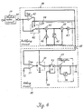
- the rectifier 11 comprises an absolute value circuit 59, a rectifying circuit 38 and an adding circuit 39.
- the rectifying circuit 38 comprises an input terminal 40, a comparator 41 having one input terminal connected to the input terminal 40, a switching circuit 42 having one input terminal connected to the input terminal 40, a low-pass filter 48 comprising adders 43 and 44, a unit clock delay element 45 and constant multipliers 46 and 47 for multiplying input signals by constants, and an output terminal 49.
- the output terminal of the constant multiplier 47 is connected to one of the input terminals of the comparator 41 and to the other input terminal of the switching circuit 42.
- the switching circuit 42 changes the input to the adder 43 according to the output of the comparator 41.
- the output of the rectifying circuit 38 is applied via the output terminal 49 to the adding circuit 39.
- the adding circuit 39 comprises a switching circuit 50, a comparator 51, an input terminal 52, a D-flip-flop 53, a terminal 54, an integrator 57 comprising an adder 55 and a unit clock delay element 56, and an output terminal 58.
- the output of the detecting circuit 38 is transferred through the output terminal 49 to the switching circuit 50 and the comparator 51 of the adding circuit 39.
- a signal of a predetermined level is applied to the input terminal 52.
- the signal applied to the input terminal 52 is compared with the output of the rectifying circuit 38 by the comparator 51, and the switching circuit 50 is controlled by the output of the comparator 51.
- a plurality of D-flip-flops are provided and the number of the D-flip-flops corresponds to the number of bits of the signal to be processed.
- the data holding timing of the D-flip-flop 53 for holding the output data of the switching circuit 50 is determined by a horizontal synchronizing signal applied to the terminal 54.
- An adder 55 and a unit clock delay element 56 which is a recursive delay element the output of which is fed back to the input constitute an integrator 57.
- the frequency of the clock applied to the delay element 56 is synchronous with the horizontal synchronizing signal.
- An absolute value circuit 59 applies the absolute value of an input signal applied to the rectifier 11 to the input terminal 40. Since the contact of the switching circuit 40 connected to the input terminal 40 is closed, the input signal is transferred to the low-pass filter 48. The output of the low-pass filter 48 is compared with the input signal by the comparator 41. When the output signal is greater than the input signal, the comparator 41 provides an output to close the contact of the switching circuit 42 connected to the output terminal of the low-pass filter 48, so that the output of the low-pass filter 48 is held. This operation is continued during a horizontal scanning period. Consequently, a peak value of a band in one line of the image signal limited by the low-pass filter 48 is held.
- the low-pass filter 48 removes high-frequency noise, which is different from the function of a simple peak value holding circuit.
- the rectifying circuit 38 is reset by a horizontal synchronizing signal and starts the rectification cycle for the next line.
- the waveform of the output signal of the rectifying circuit 38 is shown in Fig. 8(g).
- the peak value in one line of the image signal thus held is applied to the adding circuit 39 .
- a value corresponding to an output level of the rectifying circuit 38 when only a noise component (hereinafter referred to as "noise level”) is applied to the same is applied to the input terminal 52 of the comparator 51.
- the comparator 51 and the switching circuit 50 inhibit the application of the input signal applied to the adding circuit 39 to the integrator 57 when the level of the input signal is lower than the noise level.
- the D-flip-flop 53 makes the integrator 57 execute integration for each line to obtain an integral of the input signals for one field period.
- the integral appears at the output terminal 58.
- the adding circuit 39 is reset by a vertical synchronizing signal to start operation for the next field.
- the rectifier 11 Since signals of a level below the noise level are removed even if the object has high-frequency signal components only in several lines on an image plane, such as a fly on a white wall, only the signals for lines including high-frequency signal components are added and an output can be obtained without being removed together with noise.
- the level of a signal spanning n lines is multiplied by n because the signal is added n times by the integrator 57, whereas the noise is multiplied merely by ⁇ n. Accordingly, the SN ratio of the output signal of the adding circuit 39 is improved.
- digital signals corresponding to the image signals are processed, and hence peak values are held without fail.
- the line signals can be achieved by means of a very simple construction.
- the rectifier 11 provides the horizontal high-frequency signal components of the image plate.
- the mode of operation for obtaining the vertical high-frequency signal components is the same as that for obtaining the horizontal high-frequency signal components, except that a filter circuit is used for obtaining the vertical high-frequency signal components.
- the vertical BPF 14 comprises an input terminal 60, an adder 61, subtractors 62 and 63, a one-scanning-period delay element 64, such as a first-in first-out circuit (hereinafter abbreviated as "FIFO"), a constant multiplier 65 and an output terminal 66.
- the constant multiplier 65 multiplies an input signal by a constant.
- the vertical BPF 14 similarly to the horizontal differentiation circuit 8, functions as a filter for removing the vertical dc components.
- the vertical cut-off frequency f c 120 TV line resolution
- the vertical BPF 14 functions, similarly to the horizontal BPF 10, as a filter for extracting the high-frequency signal components of the object, necessary for focusing.
- the vertical filter thus constituted processes vertical signals.
- the constant k for the constant multiplier 65 (Fig. 5) of the vertical differentiation circuit 12 (Fig. 1) is -0.75.
- High-frequency signal components included in the starting and ending portions of an effective vertical scanning period in a signal produced by removing dc components by the vertical differentiation circuit 12 are not the high-frequency signal components of the object. Therefore, the gate circuit 13 executes AND operation on the basis of the output signal of the vertical differentiation circuit 12 and the output signal of the gate signal generator 16 to extract only signal components corresponding to the central portion of the image plane and to eliminate signal components corresponding to unnecessary portions of the image plane.
- the rectifier 15 is similar to the rectifier 11 in construction. The rectifier 15 extracts the vertical high-frequency signal components of the object in each field period.
- the outputs of the rectifiers 11 and 15 are applied to the control unit 17, and then the control unit 17 provides a control signal to control the lens driving circuit 18 which in turn drives the lens driving mechanism 19.
- the lens driving mechanism 19 is a motor for driving the focusing lens 2.
- the control unit 17, for example, is a microcomputer. The operation of the control unit 17 will be described with reference to Figs. 6 and 7.
- the outputs of the rectifiers 11 and 15 are added by a microcomputer to obtain a focus voltage.
- Fig. 6 is a curve showing the variation of the focus voltage with the deviation of the position of the focusing lens 2 of the taking lens system 1, in which the position of the focusing lens 2 is measured on the horizontal axis, and the focus voltage, i.e., the sum of the outputs of the rectifiers 11 and 15 on the vertical axis.
- the focus voltage reaches the maximum level.
- the level of the focus voltage decreases as the degree of unfocused state of the taking lens system 1 increases, hence, the curve has a generally upward convex shape having a peak point.
- Dn represents a focus voltage for the nth field
- Dn-1 represents a focus voltage for the (n-1)th field.
- the automatic focusing apparatus in the above description comprises the horizontal BPF for extracting the horizontal high-frequency components from the output of the pickup element, the vertical BPF for extracting the vertical high-frequency components from the output of the pickup element, the rectifiers for rectifying the outputs of the horizontal and vertical BPFs, the control unit which provides control signals to control the lens driving mechanism for driving the taking lens system or the focusing lens unit of the taking lens system, and the driving circuit for driving the lens driving mechanism according to the control signals provided by the control unit, the automatic focusing apparatus carries out the focusing operation on the basis of the focus voltage signal including the vertical data of the image plane in addition to the horizontal data of the same.
- the automatic focusing apparatus of the above description is able to focus the taking lens system on an object, such as a horizontal line, for which the conventional automatic focusing apparatus are unable to focus the taking lens system. Since an increased quantity of information is available for focusing the taking lens system on an object having information for both the horizontal and vertical directions, the possible focusing range is expanded.
- the detecting circuit which limits the band, and the adding circuit which eliminates the noise components and adds the signal components reduce the noise components in the focus voltage, which enables stable focusing operation.
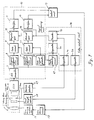
- the automatic focusing apparatus in this embodiment is different from the automatic focusing apparatus shown in Fig. 1 in that at least one of a peak detecting circuit 67, a focal length detector 68 and an aperture detector 69 are provided to detect the condition of the object, and a filter control unit 74 is provided to change the characteristics of filters for extracting high-frequency signal components, on the basis of the output signals of the peak detecting circuit 67, the focal length detector 68 and the aperture detector 69.
- a horizontal BPF 75 and a vertical BPF 76 are the same in constitution as the horizontal BPF 10 (Fig. 3) and the vertical BPF (Fig. 5), respectively.
- the constants k set for the constant multipliers of the horizontal BPF 75 and the vertical BPF 76 are changed selectively by the filter control unit 74 to vary the cut-off frequencies of the horizontal BPF 75 and the vertical BPF 76.
- the filter control unit 74 comprises comparators 70, 71 and 72 for respectively comparing the outputs of the peak detecting circuit 67, the aperture detector 69 and the focal length detector 68 with respective predetermined levels, and a decoder which provides filter control signals on the basis of the outputs of the comparators 70, 71 and 72.
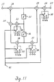
- the horizontal BPF 75 is provided, in addition to the components of the horizontal BPF 10 shown in Fig. 3, with constant selectors 86, 87, 88 and 89 for respectively selectively changing constants for constant multipliers 33, 34, 35 and 36.
- a constant selector control signal is applied to an input terminal 85 connected to the output terminal of the filter control unit 74 (Fig. 9).
- the constant selector 86 selects a constant a1, a2 or in accordance with the control signal applied to the input terminal 85.
- the peak detecting circuit 67 comprises an input terminal 77 to which the output signal of an A/D converter 7 (Fig. 9) is applied, an input terminal 78 to which the output signal of a gate signal generator 16 (Fig.
- an AND circuit 79 is applied, an AND circuit 79, a digital comparator 80, D-flip-flops 81 and 83 (actually, a plurality of D-flip-flops 81 and a plurality of D-flip-flops 83 are provided and the number of the D-flip-flops 81 and that of the D-flip-flops 83 correspond to the number of bits of signal), an input terminal 82 to which a vertical synchronizing signal is applied, and an output terminal 84.
- the output of the AND circuit 79 is a signal representing a portion for focusing extracted from an image plane.
- the output of the AND circuit 79 is applied to one of the input terminals of the digital comparator 80 and to the D-flip-flop 81.
- the clock terminal of the D-flip-flop 81 is connected to the output terminal of the digital comparator 80.
- the output of the digital comparator 80 is HIGH when the output signal of the AND circuit 79 is large.
- the output of the AND circuit 79 is latched by the D-flip-flop 81.
- the output terminal of the D-flip-flop 81 is connected to the other input terminal of the digital comparator 80, and hence the output terminal of the D-flip-flop 81 holds the maximum output of the AND circuit 79.
- the D-flip-flop 81 is reset by a vertical synchronizing signal applied to the input terminal 82, and the D-flip-flop 83 latches data.
- the maximum output of the AND circuit 79 in one field appears at the output terminal 84. Since the input signal of the AND circuit 79 is not processed by a differentiation circuit, the input signal contains the dc component of an image signal. Accordingly, the maximum output of the AND circuit 79 corresponds to the maximum value of the image signal representing a portion of the object having the maximum luminance. Thus, the peak detecting circuit 67 provides the maximum level of luminance of the object in a region extracted by the AND circuit 79.
- the output of the peak detecting circuit 67 is compared with a predetermined value by the comparator 70.
- the decoder 73 provides an output signal to shift the respective pass bands of the horizontal BPF 75 and the vertical BPF 76 to the lower side.
- the amplitude decreases with increase in the frequency. Therefore, the shift of the pass band to the lower side increases the level of the output. Accordingly, a focus voltage of a sufficiently high level can be secured to enable focusing operation even for a low luminance object.
- the pass band of the BPF When the pass band of the BPF is high, the level of the focus voltage is low, while the curve indicating the variation of the focus voltage with the deviation of the position of the focusing lens has a sharp shape, and hence focusing accuracy is improved.
- the pass band of the BPF When the pass band of the BPF is low, the level of the focus voltage is high, while the curve has a comparatively flat upward convex shape, and hence focusing accuracy is deteriorated.
- the BPF is set for a high pass band to focus the taking lens system at a high accuracy.
- the range of detection of the unfocused condition of the taking lens system is wide because the image signal contains only a small quantity of high-frequency components. Accordingly, the pass band is shifted to the lower side to raise the level of the focus voltage. Thus, stable focusing operation can be achieved even if the luminance of the object is low.
- a method of focusing the taking lens system 1 through the detection of the focal length and aperture of the taking lens system 1 will be described hereinafter. First the influence of the f number and the variation of the focal length on the shape of the focus voltage curve will be explained.
- the depth d of focus is the range of distance of the image behind the taking lens system 1 through which the image has acceptable sharpness and is proportional to the f number of the taking lens system 1.
- the focus voltage curve indicates the relation between the minuteness of the image plane and the degree of unfocused state
- the gradient of the focus voltage curve is approximately proportional to the f number, namely, the gradient decreases with increase in the f number.
- the gradient of the focus voltage curve is greatly dependent on the f number and the variation of the focal length. If the shape of the focus voltage curve varies greatly, it is impossible to secure sufficiently high focusing accuracy, and the response speed of focusing operation is decreased; that is, the focus voltage curve is gentle and the variation of the focus voltage between fields is small when the aperture of the taking lens system 1 is small or when the focal length is small, and hence the sensitivity of detection is deteriorated.
- the focal length of the taking lens system 1 is varied by shifting the variator lens 3. Accordingly, the focal length detector 68 detects the position of the variator lens 3.
- a rheostat comprising a resistor, and a slider attached to the variator lens 3 so as to slide along the resistor may be provided to detect the position of the variator lens 3, namely, the focal length of the taking lens system 1, in the form of voltage.
- the aperture detector 69 detects a signal corresponding to the diameter of the diaphragm 5, namely, the f number of the taking lens system 1.
- An ordinary video camera is provided with an automatic diaphragm adjusting mechanism which is driven by a motor to adjust the diaphragm. Therefore, aperture detector 69 detects the phase of the rotor of the motor.
- the aperture detector 69 is provided with a Hall element to detect the phase of the rotor through the detection of the variation of magnetism.
- the respective outputs of the focal length detector 68 and the aperture detector 69 are given to the filter control unit 74, and then the filter control unit 74 selects the characteristics of the horizontal BPF 75 and the vertical BPF 76 on the basis of the outputs of the focal length detector 68 and the aperture detector 69, which is similar to the function of the filter control unit 74 in detecting the luminance of the object.
- the gradient of the focus voltage curve is approximately proportional to the f number.
- the taking lens system 1 is a low-pass filter
- the increase of the f number corresponds to the increase of the cut-off frequency.
- the shift of the pass bands of the horizontal BPF 75 and the vertical BPF 76 to the higher side increases the gradient of the focus voltage curve, and hence the gradient of the focus voltage curve is maintained approximately constant by shifting the pass bands to the higher side by the filter control unit 74 according to the output of the aperture detector 69 when the f number is increased. If the gradient of the focus voltage curve is constant, the output signal of the control unit 17 is constant regardless of the f number, so that stable focusing operation is possible at all times.
- the gradient of the focus voltage curve varies in proportion to the square of the variation of the focal length of the taking lens system 1 and decreases with the decrease of the focal length. Accordingly, the gradient of the focus voltage curve can be maintained constant by shifting the pass bands by the filter control unit 74 according to the output of the focal length detector 68 when the focal length is decreased.
- the provision of the peak detecting circuit, the focal length detector and the aperture detector for detecting the condition of the object, and a filter control unit for selectively changing the characteristics of the BPFs enables constantly stable focusing operation regardless of the condition of the object.
- the number of component parts increases according to the number of necessary pass bands in constructing an analog BPF.
- the pass band of the BPF can be changed simply by changing the coefficient of the BPF, which enables a highly accurate automatic focusing apparatus to be constructed in a compact construction by using LSIs.
- an improved automatic focusing apparatus can be constructed by additionally providing the conventional automatic focusing apparatus with a vertical filter capable of extracting the vertical frequency component of an analog signal.
- the control unit 17 may be designed so as to use the outputs of the rectifiers 11 and 15 alternately.
- the constants for the constant multipliers are varied selectively to vary the cut-off frequencies of the BPFs in the preferred embodiment, the constitution of the BPFs may be changed to vary the cut-off frequencies.
Landscapes
- Physics & Mathematics (AREA)
- Engineering & Computer Science (AREA)
- Computer Vision & Pattern Recognition (AREA)
- General Physics & Mathematics (AREA)
- Optics & Photonics (AREA)
- Multimedia (AREA)
- Signal Processing (AREA)
- Automatic Focus Adjustment (AREA)
Claims (7)
- Dispositif de mise au point automatique comprenant : un système d'objectif de prise de vue (1), incluant une lentille de mise au point (2) ;
un moyen de conversion photo-électrique (6) pour convertir une image optique d'un objet formé par le système d'objectif en un signal électrique correspondant ;
un moyen de traitement de signal (91) pour traiter un signal de sortie du moyen de conversion photo-électrique pour obtenir un signal de focalisation correspondant aux nombres de composants haute fréquence d'un plan d'image, le moyen de traitement de signal comprenant un moyen de filtrage (75, 76) pour extraire une composante de signal haute fréquence du signal de sortie du moyen de conversion photo-électrique ;
un moyen d'entraînement de lentille (18, 19) pour entraîner la lentille de mise au point ; et,
un moyen de commande (17) sensible au signal de focalisation provenant du moyen de traitement de signal pour commander le moyen d'entraînement de lentille pour la mise au point,
caractérisé en ce qu'il comprend en outre :
un moyen de détection (67, 68, 69) pour détecter l'amplitude d'un signal, ou de signaux, représentant au moins l'un de la luminance de l'objet, du nombre f du système d'objectif de prise de vue et de la distance focale du système d'objectif de prise de vue, et pour sortir un signal de détection indicatif d'un résultat de détection ; et,
un moyen de commande de filtre (74) sensible au signal de détection provenant du moyen de détection pour changer une caractéristique de filtrage du moyen de filtrage (75, 76). - Dispositif de mise au point automatique selon la revendication 1, dans lequel le moyen de filtrage (75, 76) comprend un filtre horizontal (75) pour extraire une composante horizontale de signal haute fréquence du signal de sortie du moyen de conversion photo-électrique, et un filtre vertical (76) pour extraire une composante verticale de signal haute fréquence du signal de sortie du moyen de conversion photo-électrique, et dans lequel le moyen de commande de filtre (74) est sensible au moyen de détection provenant du moyen de détection pour changer une caractéristique de filtrage d'au moins l'un des filtres horizontal et vertical.
- Dispositif de mise au point automatique selon les revendications 1 ou 2, dans lequel le moyen de traitement de signal (91) comprend :
un moyen générateur de signal de déblocage (16) pour produire un signal de déblocage indicatif d'une partie centrale du plan d'image ; un moyen de différentiation horizontale (8) pour retirer une composante de courant continu d'un signal horizontal inclus dans le signal de sortie du moyen de conversion photo-électrique ; un premier moyen formant porte (9) sensible au signal de déblocage pour échantillonner des signaux sur un axe des temps à partir d'un signal de sortie du moyen de différentiation horizontale, un filtre passe-bande horizontal (75) pour extraire une composante horizontale de signal haute fréquence d'un signal de sortie du premier moyen formant porte ; un premier moyen de redressement (11) pour redresser une sortie du filtre passe-bande horizontal pour produire un premier signal de focalisation ; un moyen de différentiation verticale (12) pour retirer une composante de courant continu d'un signal vertical inclus dans le signal de sortie du moyen de conversion photo-électrique ; un second moyen formant porte (13) sensible au signal de déblocage pour échantillonner des signaux sur un axe des temps à partir d'un signal de sortie du moyen de différentiation verticale, un filtre passe-bande vertical (76) pour extraire une composante verticale de signal haute fréquence d'un signal de sortie du second moyen formant porte ; un second moyen de redressement (15) pour redresser une sortie du filtre passe-bande vertical pour produire un second signal de focalisation ; et,
dans lequel le moyen de commande de filtre (74) est sensible au signal de détection provenant du moyen de détection pour changer une caractéristique de filtrage d'au moins l'un des filtres passe-bande horizontal et vertical. - Dispositif de mise au point automatique selon la revendication 1, dans lequel ;
un moyen de traitement de signal (91) sert à traiter un signal de sortie du moyen de conversion photo-électrique pour obtenir, respectivement, des premier et second signaux de focalisation correspondant aux nombres des composants haute fréquence horizontaux et verticaux d'un plan d'image, et comprend un moyen de filtrage horizontal (8, 9, 10, 75) pour extraire une composante horizontale de signal haute fréquence du signal de sortie du moyen de conversion photo-électrique, et un moyen de redressement horizontal (11) pour redresser une sortie du moyen de filtrage horizontal pour obtenir le premier signal de focalisation ;
et dans lequel ledit moyen de redressement (11) comprend :
un moyen de détection de pic maximal (59, 38) pour détecter un niveau de pic maximal de la sortie du moyen de filtrage horizontal dans chaque ligne horizontale ; et,
un moyen d'addition (39) pour additionner de façon cumulative les sorties du moyen de détection de pic maximal dans chaque trame pour obtenir le premier signal de focalisation. - Dispositif de mise au point automatique selon la revendication 4, dans lequel ledit moyen de détection de pic maximal (59, 38) comprend ; un circuit de valeur absolue (59) pour fournir une valeur absolue de la sortie du moyen de filtrage horizontal ; un filtre passe-bas (48) ; un comparateur (41) pour comparer un signal de sortie du filtre passe-bas et un signal de sortie du circuit de valeur absolue ; et un moyen de commutation (42) sensible à un signal de sortie du comparateur pour appliquer au filtre passe-bas, de manière sélective, soit le signal de sortie du filtre passe-bas soit le signal de sortie du circuit de valeur absolue.
- Dispositif de mise au point automatique selon la revendication 4, dans lequel ledit moyen d'addition (39) comprend un comparateur (51) pour comparer un niveau d'une sortie du moyen de détection de pic maximal (59, 38) à un niveau prédéterminé ; un moyen de commutation (50) sensible à une sortie du comparateur pour délivrer de manière sélective soit le signal d'entrée soit un signal de niveau zéro ; et un intégrateur (57) pour intégrer les signaux de sortie du moyen de commutation.
- Dispositif de mise au point automatique selon la revendication 4, dans lequel le moyen de traitement de signal (90, 91) comprend : un moyen générateur de signal de déblocage (16) pour produire un signal de déblocage indicatif d'une partie centrale du plan d'image ; un moyen de différentiation horizontale (8) pour retirer une composante de courant continu d'un signal horizontal inclus dans le signal de sortie du moyen de conversion photo-électrique ; un premier moyen formant porte (9) sensible au signal de déblocage pour échantillonner des signaux sur un axe des temps à partir d'un signal de sortie du moyen de différentiation horizontale, un filtre passe-bande horizontal (10, 75) pour extraire une composante horizontale de signal haute fréquence d'un signal de sortie du premier moyen formant porte ; le premier moyen de redressement (11) pour redresser une sortie du filtre passe-bande horizontal pour produire un premier signal de focalisation ; un moyen de différentiation verticale (12) pour retirer une composante de courant continu d'un signal vertical inclus dans le signal de sortie du moyen de conversion photo-électrique ; un second moyen formant porte (13) sensible au signal de déblocage pour échantillonner des signaux sur un axe des temps à partir d'un signal de sortie du moyen de différentiation verticale, un filtre passe-bande vertical (14, 76) pour extraire une composante verticale de signal haute fréquence d'un signal de sortie du second moyen formant porte ; un moyen de redressement vertical (15) pour redresser une sortie du filtre passe-bande vertical pour produire le second signal de focalisation.
Priority Applications (1)
| Application Number | Priority Date | Filing Date | Title |
|---|---|---|---|
| EP93200579A EP0548061B1 (fr) | 1987-11-25 | 1988-11-24 | Circuit de focalisation automatique |
Applications Claiming Priority (6)
| Application Number | Priority Date | Filing Date | Title |
|---|---|---|---|
| JP62296534A JPH0785574B2 (ja) | 1987-11-25 | 1987-11-25 | 自動焦点調節装置 |
| JP296534/87 | 1987-11-25 | ||
| JP63148556A JPH022791A (ja) | 1988-06-16 | 1988-06-16 | 自動焦点調節装置 |
| JP148556/88 | 1988-06-16 | ||
| JP158523/88 | 1988-06-27 | ||
| JP63158523A JPH027777A (ja) | 1988-06-27 | 1988-06-27 | 自動焦点調節装置 |
Related Child Applications (2)
| Application Number | Title | Priority Date | Filing Date |
|---|---|---|---|
| EP93200579A Division EP0548061B1 (fr) | 1987-11-25 | 1988-11-24 | Circuit de focalisation automatique |
| EP93200579.6 Division-Into | 1988-11-24 |
Publications (3)
| Publication Number | Publication Date |
|---|---|
| EP0318278A2 EP0318278A2 (fr) | 1989-05-31 |
| EP0318278A3 EP0318278A3 (en) | 1990-03-07 |
| EP0318278B1 true EP0318278B1 (fr) | 1994-03-09 |
Family
ID=27319576
Family Applications (2)
| Application Number | Title | Priority Date | Filing Date |
|---|---|---|---|
| EP93200579A Expired - Lifetime EP0548061B1 (fr) | 1987-11-25 | 1988-11-24 | Circuit de focalisation automatique |
| EP88311108A Expired - Lifetime EP0318278B1 (fr) | 1987-11-25 | 1988-11-24 | Circuit de focalisation automatique |
Family Applications Before (1)
| Application Number | Title | Priority Date | Filing Date |
|---|---|---|---|
| EP93200579A Expired - Lifetime EP0548061B1 (fr) | 1987-11-25 | 1988-11-24 | Circuit de focalisation automatique |
Country Status (4)
| Country | Link |
|---|---|
| US (1) | US4975726A (fr) |
| EP (2) | EP0548061B1 (fr) |
| KR (1) | KR910007514B1 (fr) |
| DE (2) | DE3888297T2 (fr) |
Families Citing this family (19)
| Publication number | Priority date | Publication date | Assignee | Title |
|---|---|---|---|---|
| US5070408A (en) * | 1989-05-19 | 1991-12-03 | Sony Corporation | Focusing apparatus and digital filters for use therewith |
| JPH03143173A (ja) * | 1989-10-30 | 1991-06-18 | Toshiba Corp | ビデオ・カメラの自動焦点調節装置 |
| DE3938522C2 (de) * | 1989-11-21 | 1998-09-24 | Philips Broadcast Television S | System zum Fokussieren eines Fernsehkamera-Objektivs |
| JPH03214868A (ja) * | 1990-01-19 | 1991-09-20 | Ricoh Co Ltd | 自動焦点調整装置 |
| US6130716A (en) * | 1991-08-09 | 2000-10-10 | Canon Kabushiki Kaisha | Autofocusing camera device |
| JPH05292382A (ja) * | 1992-04-15 | 1993-11-05 | Sony Corp | オートフォーカス装置 |
| JP3298146B2 (ja) * | 1992-05-29 | 2002-07-02 | ソニー株式会社 | オートフォーカス装置 |
| JPH06205269A (ja) * | 1993-01-06 | 1994-07-22 | Matsushita Electric Ind Co Ltd | 自動焦点調節装置およびビデオカメラ |
| DE4413368C1 (de) * | 1994-04-19 | 1995-09-28 | Wilfried Donner | Verfahren und Vorrichtung zur optischen Scharfeinstellung |
| JPH089228A (ja) | 1994-06-17 | 1996-01-12 | Matsushita Electric Ind Co Ltd | ビデオカメラ |
| US5666569A (en) * | 1994-08-25 | 1997-09-09 | Flashpoint Technology, Inc. | System and method for detecting and indicating proper focal distance in a fixed lens camera |
| US6373524B2 (en) * | 1995-06-22 | 2002-04-16 | Canon Kabushiki Kaisha | Interchangeable lens video camera system |
| US5874994A (en) * | 1995-06-30 | 1999-02-23 | Eastman Kodak Company | Filter employing arithmetic operations for an electronic sychronized digital camera |
| EP1109483A4 (fr) * | 1998-08-06 | 2003-05-07 | Univ Johns Hopkins | Instrument de diagnostic optique video pouvant etre mis au point par un seul reglage |
| JP2000147370A (ja) * | 1998-11-18 | 2000-05-26 | Sony Corp | 撮像装置 |
| JP4408001B2 (ja) * | 2000-12-21 | 2010-02-03 | キヤノン株式会社 | 撮像装置および撮像システム |
| JP3964315B2 (ja) * | 2002-12-03 | 2007-08-22 | 株式会社リコー | デジタルカメラ |
| JP5173131B2 (ja) * | 2005-10-26 | 2013-03-27 | キヤノン株式会社 | 光学機器および焦点調節方法 |
| JP5898481B2 (ja) * | 2011-12-13 | 2016-04-06 | キヤノン株式会社 | 撮像装置及び焦点検出方法 |
Family Cites Families (6)
| Publication number | Priority date | Publication date | Assignee | Title |
|---|---|---|---|---|
| JPS6097784A (ja) * | 1983-11-01 | 1985-05-31 | Sanyo Electric Co Ltd | オ−トフオ−カス制御回路 |
| JPS60217759A (ja) * | 1984-04-13 | 1985-10-31 | Matsushita Electric Ind Co Ltd | 自動焦点整合装置 |
| JPS61105978A (ja) * | 1984-10-30 | 1986-05-24 | Sanyo Electric Co Ltd | オ−トフオ−カス回路 |
| FR2575888B1 (fr) * | 1985-01-04 | 1987-02-20 | Thomson Csf | Procede et dispositif de mise au point d'une camera et camera comportant un tel dispositif |
| JPS6347711A (ja) * | 1986-08-18 | 1988-02-29 | Minolta Camera Co Ltd | 焦点検出装置 |
| JPS63178674A (ja) * | 1987-01-19 | 1988-07-22 | Sanyo Electric Co Ltd | オ−トフオ−カス回路 |
-
1988
- 1988-11-18 US US07/272,898 patent/US4975726A/en not_active Expired - Lifetime
- 1988-11-24 EP EP93200579A patent/EP0548061B1/fr not_active Expired - Lifetime
- 1988-11-24 DE DE3888297T patent/DE3888297T2/de not_active Expired - Fee Related
- 1988-11-24 DE DE3856250T patent/DE3856250T2/de not_active Expired - Lifetime
- 1988-11-24 EP EP88311108A patent/EP0318278B1/fr not_active Expired - Lifetime
- 1988-11-25 KR KR1019880015561A patent/KR910007514B1/ko not_active IP Right Cessation
Also Published As
| Publication number | Publication date |
|---|---|
| EP0548061A3 (en) | 1994-05-18 |
| DE3888297D1 (de) | 1994-04-14 |
| EP0318278A3 (en) | 1990-03-07 |
| EP0318278A2 (fr) | 1989-05-31 |
| US4975726A (en) | 1990-12-04 |
| DE3888297T2 (de) | 1994-08-04 |
| KR910007514B1 (ko) | 1991-09-26 |
| DE3856250D1 (de) | 1998-10-15 |
| EP0548061B1 (fr) | 1998-09-09 |
| DE3856250T2 (de) | 1999-02-04 |
| KR890009180A (ko) | 1989-07-15 |
| EP0548061A2 (fr) | 1993-06-23 |
Similar Documents
| Publication | Publication Date | Title |
|---|---|---|
| EP0318278B1 (fr) | Circuit de focalisation automatique | |
| US4990947A (en) | Automatic focusing apparatus | |
| US5083150A (en) | Automatic focusing apparatus | |
| US6271883B1 (en) | Automatic focusing apparatus for a video camera | |
| EP0488723B1 (fr) | Appareil de détection de vecteur de mouvement | |
| Ooi et al. | An advanced autofocus system for video camera using quasi condition reasoning | |
| US4717959A (en) | Automatic focusing device for video camera or the like | |
| US5077613A (en) | Video camera with automatic focusing function | |
| EP0398368B1 (fr) | Dispositif de focalisation et filtres numériques à cet effet | |
| JPS63128878A (ja) | 合焦検出装置 | |
| EP0456320B1 (fr) | Dispositif de focalisation automatique | |
| US5739858A (en) | Automatic focusing device using a plurality of different frequency components extracted at the same point | |
| JPH05316401A (ja) | 焦点自動検出装置 | |
| US6239838B1 (en) | Camera apparatus for detecting focus value engaged to output picture | |
| JPH05145827A (ja) | 自動焦点調節装置 | |
| US4587416A (en) | Focus detecting apparatus for microscope or camera | |
| JPH01137886A (ja) | 自動焦点調節装置 | |
| KR970001570B1 (ko) | 카메라의 자동촛점 제어방법 | |
| JPH027777A (ja) | 自動焦点調節装置 | |
| JPH06165017A (ja) | 自動焦点検出装置 | |
| JPS62146081A (ja) | 自動焦点整合装置 | |
| JP2603535Y2 (ja) | オートフォーカス装置 | |
| JPH0785574B2 (ja) | 自動焦点調節装置 | |
| JPS63276981A (ja) | オ−トフオ−カス回路 | |
| JPH0614240A (ja) | 撮像装置 |
Legal Events
| Date | Code | Title | Description |
|---|---|---|---|
| PUAI | Public reference made under article 153(3) epc to a published international application that has entered the european phase |
Free format text: ORIGINAL CODE: 0009012 |
|
| AK | Designated contracting states |
Kind code of ref document: A2 Designated state(s): DE FR GB |
|
| PUAL | Search report despatched |
Free format text: ORIGINAL CODE: 0009013 |
|
| AK | Designated contracting states |
Kind code of ref document: A3 Designated state(s): DE FR GB |
|
| 17P | Request for examination filed |
Effective date: 19900810 |
|
| 17Q | First examination report despatched |
Effective date: 19920630 |
|
| GRAA | (expected) grant |
Free format text: ORIGINAL CODE: 0009210 |
|
| AK | Designated contracting states |
Kind code of ref document: B1 Designated state(s): DE FR GB |
|
| REF | Corresponds to: |
Ref document number: 3888297 Country of ref document: DE Date of ref document: 19940414 |
|
| ET | Fr: translation filed | ||
| PLBE | No opposition filed within time limit |
Free format text: ORIGINAL CODE: 0009261 |
|
| STAA | Information on the status of an ep patent application or granted ep patent |
Free format text: STATUS: NO OPPOSITION FILED WITHIN TIME LIMIT |
|
| 26N | No opposition filed | ||
| REG | Reference to a national code |
Ref country code: GB Ref legal event code: 746 Effective date: 19950928 |
|
| REG | Reference to a national code |
Ref country code: FR Ref legal event code: D6 |
|
| REG | Reference to a national code |
Ref country code: GB Ref legal event code: IF02 |
|
| PGFP | Annual fee paid to national office [announced via postgrant information from national office to epo] |
Ref country code: FR Payment date: 20051108 Year of fee payment: 18 |
|
| PGFP | Annual fee paid to national office [announced via postgrant information from national office to epo] |
Ref country code: DE Payment date: 20051117 Year of fee payment: 18 |
|
| PGFP | Annual fee paid to national office [announced via postgrant information from national office to epo] |
Ref country code: GB Payment date: 20051123 Year of fee payment: 18 |
|
| PG25 | Lapsed in a contracting state [announced via postgrant information from national office to epo] |
Ref country code: DE Free format text: LAPSE BECAUSE OF NON-PAYMENT OF DUE FEES Effective date: 20070601 |
|
| GBPC | Gb: european patent ceased through non-payment of renewal fee |
Effective date: 20061124 |
|
| REG | Reference to a national code |
Ref country code: FR Ref legal event code: ST Effective date: 20070731 |
|
| PG25 | Lapsed in a contracting state [announced via postgrant information from national office to epo] |
Ref country code: GB Free format text: LAPSE BECAUSE OF NON-PAYMENT OF DUE FEES Effective date: 20061124 |
|
| PG25 | Lapsed in a contracting state [announced via postgrant information from national office to epo] |
Ref country code: FR Free format text: LAPSE BECAUSE OF NON-PAYMENT OF DUE FEES Effective date: 20061130 |