EP0316121A2 - Dispositif à diaphragme - Google Patents
Dispositif à diaphragme Download PDFInfo
- Publication number
- EP0316121A2 EP0316121A2 EP88310436A EP88310436A EP0316121A2 EP 0316121 A2 EP0316121 A2 EP 0316121A2 EP 88310436 A EP88310436 A EP 88310436A EP 88310436 A EP88310436 A EP 88310436A EP 0316121 A2 EP0316121 A2 EP 0316121A2
- Authority
- EP
- European Patent Office
- Prior art keywords
- diaphragm
- annular
- cup
- shaped
- marginal portion
- Prior art date
- Legal status (The legal status is an assumption and is not a legal conclusion. Google has not performed a legal analysis and makes no representation as to the accuracy of the status listed.)
- Granted
Links
Images


Classifications
-
- F—MECHANICAL ENGINEERING; LIGHTING; HEATING; WEAPONS; BLASTING
- F16—ENGINEERING ELEMENTS AND UNITS; GENERAL MEASURES FOR PRODUCING AND MAINTAINING EFFECTIVE FUNCTIONING OF MACHINES OR INSTALLATIONS; THERMAL INSULATION IN GENERAL
- F16J—PISTONS; CYLINDERS; SEALINGS
- F16J3/00—Diaphragms; Bellows; Bellows pistons
- F16J3/02—Diaphragms
Definitions
- the present invention relates to diaphragm devices, such as those used in a vacuum advance mechanism of a distributor for an internal combustion engine, and more particularly to improvements in the mounting and sealing structure of diaphragms therein.
- Diaphragm devices are used, for example, in a vacuum advance mechanism of a distributor for an internal combustion engine.
- diaphragms are usually tightly clamped between two rigid flat members at the marginal portions thereof, to define with a housing member a hermetically sealed chamber.
- Fig. 1a shows an axial cross section of an example of a diaphragm device which forms part of a vacuum advance mechanism of a distributor for an internal combustion engine.
- the housing of the device consists of two cup-shaped members, housing top 1a and bottom 1b, and a diaphragm 2 is tightly held between the housing top 1a and the housing bottom 1b at the outer marginal portion thereof, to define with the housing top 1a a vacuum chamber 3a thereabove, and an atmospheric pressure chamber 3b therebelow with the housing bottom 1b.
- the central portion of the diaphragm 2 is held between a pair of stiffening disks 4a and 4b of metal which are clamped together by rivets 5a and 5b.
- a control rod 6 is coupled to a central convex portion of the lower stiffening disk 4b at the top end thereof, and extends through a central aperture 1c of the housing bottom 1b.
- the other end of the control rod 6 is coupled to the ignition advancing plate (not shown) within the distributor to transmit axial displacement of the diaphragm 2 thereto so that the ignition timing is advanced in proportion to the displacement.
- a helical spring 7 reacting against the bottom portion of the cup-shaped housing top 1a bears against the upper stiffening disk 4a to urge the diaphragm 2 to the neutral or zero advance position.
- a suction pipe 1d communicates the vacuum chamber 3a to a portion of an intake manifold (not shown) of the internal combustion engine immediately upstream of an unillustrated throttle thereof, so that suction from the chamber 3a through the pipe 1d increases as the degree of opening of the throttle increases.
- the atmospheric pressure chamber 3b communicates with the atmosphere through the central aperture 1c formed in the housing bottom 1b.
- Fig. 1b is an enlarged view of the portion within circle A in Fig. 1a, showing the mounting and sealing structure of the outer marginal portion of the diaphragm.
- the marginal portion of the housing top 1a is formed into a radially extending flat annular flange 10a.
- the marginal portion of the bottom 1b of the housing is formed into a clamping structure of inwardly open U-shaped cross section, wherein the outer marginal portion 2a of the diaphragm 2 is inserted between a radially outwardly extending flat annular flange portion 10b of the U-shaped marginal structure of the housing bottom 1b and a flange 10a of the housing top 1a, the flange 10a and the marginal portion 2a of the diaphragm 2 being held between the flange portion 10b and the inwardly bent extension 11b of the U-shaped marginal portion of the housing bottom 1b.
- the two radially extending flat annular portions 10b and 11b of the housing bottom 1b are clamped together by a press, so that the marginal portion 2a of the diaphragm 2 is held tightly between the flanges 10a and 10b of the housing top 1a and the housing bottom 1b, wherein the thickness of the clamped marginal portion 2a of the diaphragm 2 is reduced by the clamping pressure, compared with the original thickness of the non-compressed portion of the diaphragm 2, thereby ensuring airtight sealing thereat.
- the mounting structure of the diaphragm shown in Fig. 1b has the following disadvantage. Namely, even when the pressure and the stroke of the clamping press are maintained strictly at predetermined magnitudes, the thickness reduction in the marginal portion 2a of the diaphragm 2 due to the clamping force tends to vary from one device to another and can hardly be maintained at a constant magnitude, due to random variations in the component parts, etc. Thus, if the thickness reduction of the diaphragm 2 by clamping force happens to be too great, the clamped marginal portion 2a of the diaphragm 2 may be stretched beyond limit and torn thereat. On the other hand, too small thickness reduction at the clamped marginal portion 2a of the diaphragm 2 may result in inadequate airtight sealing thereat.
- Fig. 2a shows another diaphragm device forming part of a vacuum advance mechanism of a distributor for an internal combustion engine.
- the structure and operation of the device of Fig. 2a is similar to those of the device of Fig. 1a, wherein like reference numerals represent like or corresponding parts or portions.
- the inner marginal portion of an annular diaphragm 2 is mounted, together with inner marginal portions of the annular stiffening disks 4a and 4b, to a top end portion 6a of a control rod 6. Namely, as shown in Fig. 2b illustrating the portion within circle B in Fig.
- the inner marginal portion 2b of the diaphragm 2 held between the inner marginal portions of annular stiffening disks 4a and 4b is inserted together therewith into an annular recess formed in the side surface of a cylindrical top portion 6a of a control rod 6 to be tightly clamped therein between the disks 4a and 4b, wherein the thickness of a clamped inner marginal portion 2b is reduced by the clamping pressure exerted thereon, compared with the original thickness of the unclamped portion of the diaphragm 2, so that airtight sealing thereat is ensured.
- the mounting structure of the inner marginal portion 2b of the diaphragm 2 to the control rod 6 has the same disadvantage as the mounting structure of the outer marginal portion of the diaphragm shown in Fig. 1b. Namely, the unavoidable variation in the clamping thickness reduction results in a failure or an unsufficient sealing of the clamped inner marginal portion 2b of the diaphragm 2.
- U.S. patent No. 3,572,301 discloses a vacuum advance mechanism including a diaphragm device which has a structure different from those described above.
- Each one of the diaphragm devices disclosed in the U.S. patent comprises two annular diaphragms, the outer marginal portions of which are held tightly between a radially extending annular flange portion of a housing member and a flat annular surface of a rigid spacer ring opposing thereto.
- An annular inner marginal portion of one of the diaphragms of a first device shown in Fig.
- an object of the present invention is to provide a diaphragm device, such as those used in a vacuum advance mechanism of a distributor for an internal combustion engine, wherein a diaphragm can be mounted in an airtight manner without any danger of causing damage to the diaphragm. More particularly, the present invention aims at providing a diaphragm device in which the diaphragm can be mounted in such a way that the thickness reduction of the tightly clamped marginal portions of the diaphragm due to the clamping pressure exerted thereon can be controlled to an optimum magnitude to ensure airtight engagement without incurring any danger of failure to the diaphragm thereat.
- a further object of the present invention is to provide such a diaphragm device which is simple in structure and can be produced at low cost.
- a still further object of the present invention is to provide a mounting and sealing structure of a diaphragm which is applicable to a wide variety of diaphragm devices including all the above-described types.
- a diaphragm device comprises a housing and a diaphragm extending therein to define an airtight chamber.
- the housing may comprise, for example, two cup-shaped members coupled to each other at the marginal portions thereof.
- the diaphragm may be disk-shaped or annular, and is mounted to the housing at the outer marginal portion thereof.
- the inner marginal portion of the diaphragm is mounted and sealed, for example, to a rod-shaped member such as a control rod of the diaphragm device of a vacuum advance mechanism.
- the inner or outer marginal portion of the diaphragm is clamped between two opposing surface members, the distance between the two surfaces being regulated by distance regulating means, which comprises, for example, an annular member extending from one of the two surfaces to the other surface to determine the distance therebetween.
- the two surfaces clamping therebetween the outer marginal portion of the diaphragm may comprise the radially outwardly extending flanges of the two cup-shaped members formed at the marginal portion thereof; the distance regulating means in such a case may comprise a step formed in one of the flanges, the outer marginal portion of the diaphragm being tightly received between the stepped-down portion in an inner half of the stepped flange and an opposing surface of the other flange.
- the diaphragm may have an annular bead of enlarged thickness formed at the outer marginal portion thereof, which is tightly received in a groove formed in the opposing flange of one of the cup-shaped members.
- the distance regulating means comprises a peripheral extension of one of the two clamping surface members which is bent into the axial direction toward the other clamping surface.
- This mounting and sealing structure is applicable to the mounting of both the inner and outer marginal portions of the diaphragm.
- FIG. 3 of the drawings a first embodiment according to the present invention is described.
- Fig. 3 shows the mounting and sealing structure of a diaphragm of a diaphragm device forming part of a vacuum advance mechanism of an internal combustion engine.
- the overall structure of the diaphragm device of Fig. 3 is similar to that shown in Fig. 1a or 2a.
- the marginal portion of a cup-shaped housing top 1a is formed into a radially outwardly extending annular flange 10a.
- the marginal portion of a cup-shaped housing bottom 1b is formed into a radially outwardly extending annular flange 10b, the peripheral portion thereof being bent first into the axial direction and then into radially inward direction to form a U-shaped cross-sectional clamping structure, the peripheral portion of the flange 10a being inserted between the two radially extending opposing flat annular portions 10b and 11b thereof.
- the outer half portion of the radially outwardly extending flange portion 10b is stepped in the axial direction toward the flange 10a of the housing top 1a by a height M, which is smaller than the original or non-compressed thickness L of the diaphragm 2.
- An outer marginal portion 2a of the diaphragm 2 is held tightly between a stepped-down portion 12b of the flange 10b of the housing bottom 1b and the flange 10a of the housing top 1a, the thickness of the clamped outer marginal portion 2a being compressed by a predetermined difference (L-M) between the original thickness L of the diaphragm 2 and the height M of the step.
- the outer marginal portion of the diaphragm 2 is mounted and sealed as shown in Fig. 3 as follows. First, the outwardly extending flanges 10a and 10b of the housing top 1a and the housing bottom 1b are formed, respectively. Further, the step is formed in the flange 10b of the housing bottom 1b, and the peripheral portion of the flange 10b is bent into the axial direction. Next, the outer marginal portion 2a of the diaphragm 2 is positioned on the stepped-down portion 12b of the flange 10b of the housing bottom 1b, as shown in Fig. 3, and the flange 10a of the housing top 1a is superposed thereon.
- the axially bent peripheral portion of the flange 10b of the housing bottom 1b is bent inwardly over the flange 10a and pressed by a press to clamp the outer periphery of the flange 10a between the opposing annular flanges 10b and 11b.
- the outer marginal portion 2a is tightly pressed between the upper surface of the stepped-down portion 12b of the flange 10b and the lower surface of the flange 10a of the housing top 1a, the thickness thereof being reduced by the constant predetermined magnitude (L-M).
- Fig. 3 shows a mounting structure in which the stepped-down portion 12b for receiving the outer marginal portion 2a of the diaphragm 2 is formed in the flange 10b having the U-shaped cross-sectional clamping structure including the inwardly bent portion 11b
- the step for receiving the marginal portion 2a of the diaphragm 2 may be formed in the opposing flange 10a of the housing top 1a.
- the mounting and sealing structure shown in Fig. 3 is applicable to the mounting and sealing of the inner marginal portion of the diaphragm.
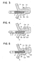
- Fig. 4 shows a second mounting and sealing structure of the outer marginal portion of a diaphragm according to the present invention.
- the structure shown in Fig. 4 is similar to that shown in Fig. 3, except that the diaphragm 2 has an annular bead 20a formed at the outer marginal portion 2a thereof and the bead 20a is received into a groove 13b formed in the stepped-down portion 12b of the flange 10b. More precisely, the annular bead 20a of semicircular cross section projects in the axial direction from the lower surface of the periphery of the outer marginal portion 2a of the diaphragm 2.
- the groove 13b formed on the upper surface of the outer portion of the stepped-down portion 12b of the flange 10b has an arc-shaped cross section of a corresponding dimension to receive the bead 20a tightly therein.
- the thickness N of the diaphragm 2 outside of the bead 20a is smaller than the drop M of the stepped-down portion 12b, so that the outer marginal portion 2a of the diaphragm 2 outside of the bead 20a is not compressed due to the existence of the clearance (M-N) thereat.
- the bead 20a is tightly received into the groove 13b and compressed between the flange 10a and the groove 13b.
- the mounting of the outer marginal portion of the diaphragm as shown in Fig. 4 can be effected substantially in the same manner as that shown in Fig. 3. Namely, the marginal portion of the cup-shaped housing bottom 1b is formed into an outwardly extending flange 10b having the stepped-down portion 12b with the groove 13b and the outer peripheral portion of the flange 10b is bent into the axial direction toward the housing top 1a. In addition, the outer marginal portion of the housing top 1a is formed into the outwardly extending flange 10a.
- the marginal portion 2a of the diaphragm 2 having the bead 20a is positioned on the stepped-down portion 12b of the flange 10b so that the bead 20a is received into the groove 13b, and the flange 10a of the housing top 1a is placed thereon as shown in Fig. 4. Further, the peripheral portion 11b of the axially-bent portion of the flange 10b is bent inwardly over the flange 10a and pressed thereon by a press. As a result, the bead 20a is tightly pressed into the groove 13b, and an airtight sealing thereat is ensured.
- Fig. 5 shows a mounting structure of the outer marginal portion of a diaphragm similar to that shown in Fig. 4.
- a bead 20a of semi-circular cross section formed at an outer marginal portion 2a of a diaphragm 2 projects from the upper surface thereof in the axial direction toward a flange 10a of a housing top 1a, in which a groove 11a of corresponding arc-shaped cross-section is formed to receive the bead 20a therein.
- the structure of Fig. 5 is similar to that of Fig. 4.
- Figs. 4 and 5 It is possible to combine the features shown in Figs. 4 and 5 to obtain a structure in which the bead formed at the outer marginal portion 2a of the diaphragm 2 projects both from upper and lower surfaces in the axial direction and grooves are formed both on the flange 10a of the housing top 1a and on the stepped-down portion 12b of the flange 10b of the housing bottom 1b. Further, the structures shown in Figs. 4 and 5 are applicable to the mounting and sealing of the inner marginal portion of an annular diaphragm.
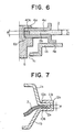
- Fig. 6 shows a mounting and sealing structure of the inner marginal portion of a diaphragm of a diaphragm device forming part of a vacuum advance mechanism of a distributor for an internal combustion engine, the overall structure of which is similar to that shown in Fig. 2a.
- An inner marginal portion 2b of an annular diaphragm 2 is tightly held between the inner marginal portions of a pair of annular disk-shaped rigid stiffening members 4a and 4b of metal sheet, and is inserted together therewith into an angular recess 6b formed on the outer side surface of a cylindrical top end portion 6a of a control rod 6 extending through a central aperture 1c in a housing bottom 1b.
- the inner edge portion of the lower stiffening disk 4b is bent in the axial direction to form a distance regulating portion 40b extending from the upper surface of the lower stiffening disk 4b to the lower surface of the upper stiffening disk 4a.
- the axial height M of the distance regulating portion 40b is smaller than the original or non-compressed thickness L of the diaphragm 2, so that the inner marginal portion 2b of the diaphragm 2 is compressed by the constant predetermined magnitude (L-M).
- the dimensions L and M may take the same values as in the case of the first embodiment shown in Fig. 3.
- the mounting of the inner marginal portion of the diaphragm as shown in Fig. 6 is effected as follows.
- the inner edge of the lower stiffening disk 4b is bent axially to form the distance regulating annular projection 40b having a height M, and the inner marginal portion 2b of the diaphragm 2 is sandwiched between the upper and lower stiffening disks 4a and 4b as shown in Fig. 6, and is inserted together therewith into the side recess 6b formed on the top end portion 6a of the control rod 6, wherein the annular recess 6b has an axial breadth enough to receive therein the inner edge portions of the stiffening disks 4a and 4b holding therebetween the inner marginal portion 2b of the diaphragm 2 having a thickness L.
- the top end of the control rod 6 is pressed by a press to reduce the axial breadth of the recess 6b until the top end of the projection 40b abuts against the lower surface of the upper stiffening disk 4a.
- the thickness of the inner marginal portion 2b of the diaphragm 2 is compressed by the constant predetermined magnitude (L-M), the axial height M of the projection 40b regulating the final distance between the surfaces of the disks 4a and 4b clamping the inner marginal portion 2b of the diaphragm 2 therebetween.
- Fig. 7 shows a mounting and sealing structure of the outer marginal portion of a diaphragm of a diaphragm device which is similar to those described above.
- the mounting structure shown in Fig. 7 is similar to that shown in Fig. 1b.
- the outer peripheral portion of the radially outwardly extending annular flange 10a is bent in the axial direction to form a distance regulating projection 12a which has a function similar to that of the projection 40b of the disk 4b shown in Fig. 6.
- the axial height M of the projection 12a regulates the axial distance between the radially outwardly extending flanges 10a and 10b clamping the outer marginal portion 2a of the diaphragm 2 therebetween, thereby controlling the thickness reduction of the clamped outer marginal portion 2a of the diaphragm 2.
- the distance regulating portions 40b and 12a are formed integrally with the stiffening disk 2b and the flange 10a, respectively. However, these distance regulating portions may be formed by separate rings of similar shapes and dimensions.
Applications Claiming Priority (6)
| Application Number | Priority Date | Filing Date | Title |
|---|---|---|---|
| JP282554/87 | 1987-11-09 | ||
| JP28255487A JPH01126469A (ja) | 1987-11-09 | 1987-11-09 | ダイアフラム装置 |
| JP28255587A JPH01126470A (ja) | 1987-11-09 | 1987-11-09 | ダイアフラム装置 |
| JP28255687A JPH01126471A (ja) | 1987-11-09 | 1987-11-09 | ダイアフラム装置 |
| JP282555/87 | 1987-11-09 | ||
| JP282556/87 | 1987-11-09 |
Publications (3)
| Publication Number | Publication Date |
|---|---|
| EP0316121A2 true EP0316121A2 (fr) | 1989-05-17 |
| EP0316121A3 EP0316121A3 (en) | 1990-01-10 |
| EP0316121B1 EP0316121B1 (fr) | 1993-09-08 |
Family
ID=27336947
Family Applications (1)
| Application Number | Title | Priority Date | Filing Date |
|---|---|---|---|
| EP88310436A Revoked EP0316121B1 (fr) | 1987-11-09 | 1988-11-07 | Dispositif à diaphragme |
Country Status (4)
| Country | Link |
|---|---|
| US (1) | US4960038A (fr) |
| EP (1) | EP0316121B1 (fr) |
| KR (1) | KR930002779B1 (fr) |
| DE (1) | DE3883921T2 (fr) |
Families Citing this family (11)
| Publication number | Priority date | Publication date | Assignee | Title |
|---|---|---|---|---|
| DE3943585C2 (de) * | 1989-08-31 | 1995-04-27 | Wagner Gmbh J | Membranpumpe |
| US5566805A (en) * | 1994-12-21 | 1996-10-22 | Dana Corporation | Vacuum operated speed range shifting mechanism |
| US5775886A (en) * | 1996-08-08 | 1998-07-07 | Terwilliger; Gerald L. | Gas compressor with reciprocating piston with valve sheath |
| US5765466A (en) * | 1997-01-24 | 1998-06-16 | Indian Head Industries | Brake actuator with self-centering diaphram |
| US5913665A (en) * | 1997-03-28 | 1999-06-22 | Tetra Laval Holdings & Finance, Sa | Fill pump with rolling diaphragms attached by vacuum to the piston |
| US5992297A (en) * | 1998-05-29 | 1999-11-30 | Indian Head Industries, Inc. | Easy fit diaphragm |
| US5979502A (en) * | 1998-10-29 | 1999-11-09 | Westinghouse Air Brake Company | Spool valve assembly |
| DE10008227A1 (de) * | 2000-02-22 | 2001-08-23 | Bosch Gmbh Robert | Vorrichtung mit einer Membrananordnung |
| US6536329B2 (en) * | 2001-04-12 | 2003-03-25 | Haldex Brake Corporation | Brake actuator having tamper resistant riveted spring chamber |
| JP2013500455A (ja) * | 2009-07-27 | 2013-01-07 | メルク・シャープ・エンド・ドーム・コーポレイション | 改良したシール性及び漏れ検出を有するダイヤフラムバルブ |
| DE102012105928A1 (de) * | 2012-07-03 | 2014-01-09 | Woco Industrietechnik Gmbh | Aktuator sowie Verfahren und Vorrichtung zur Verbindung von Gehäuseelementen eines Aktuators |
Citations (5)
| Publication number | Priority date | Publication date | Assignee | Title |
|---|---|---|---|---|
| CH317607A (de) * | 1952-07-04 | 1956-11-30 | Ici Ltd | Einrichtung zur fluidumdichten Befestigung des Randes einer biegsamen Membran und Verwendung dieser Einrichtung |
| FR1214265A (fr) * | 1958-10-23 | 1960-04-07 | Parkinson Cowan Appliances Ltd | Perfectionnements relatifs aux membranes pour compteurs à gaz ou régulateurs de gaz et similaires |
| DE1277552B (de) * | 1964-12-29 | 1968-09-12 | Commissariat Energie Atomique | Verfahren zur Herstellung von Dichtungsbaelgen |
| EP0071408A1 (fr) * | 1981-07-23 | 1983-02-09 | William R. Selwood Limited | Assemblage de diaphragme |
| EP0122440A1 (fr) * | 1983-04-16 | 1984-10-24 | Continental Aktiengesellschaft | Récipient à contenu variable spécialement pour l'usage comme vase d'expansion dans un système de chauffage de loceaux |
Family Cites Families (11)
| Publication number | Priority date | Publication date | Assignee | Title |
|---|---|---|---|---|
| US2748797A (en) * | 1951-11-08 | 1956-06-05 | Specialties Dev Corp | Pneumatic time-delay fuse |
| FR1081770A (fr) * | 1952-07-31 | 1954-12-22 | Przed Transportu Samochodowego | Dispositif d'étanchéité pour appareils hydrauliques |
| GB744889A (en) * | 1952-10-29 | 1956-02-15 | Carter Carburetor Corp | Diaphragm type fuel pump assembly |
| US2764097A (en) * | 1953-03-04 | 1956-09-25 | Lindsay H Browne | Pump |
| DE1196032B (de) * | 1963-01-31 | 1965-07-01 | Effbe Membranenwerk Fritz Brum | Membran mit beidseitig aufgelegten elastischen Dichtringen |
| US3312171A (en) * | 1965-10-12 | 1967-04-04 | New York Air Brake Co | Pumps |
| GB1539034A (en) * | 1975-04-18 | 1979-01-24 | Atomic Energy Authority Uk | Resilient coupling devices |
| US4314480A (en) * | 1980-07-14 | 1982-02-09 | Baxter Travenol Laboratories, Inc. | Venous pressure isolator |
| GB2105819B (en) * | 1981-07-23 | 1984-10-24 | Selwood Ltd William R | Diaphragm clamp |
| US4666166A (en) * | 1984-11-13 | 1987-05-19 | American Standard Inc. | Clamping arrangement for diaphragm-type piston |
| US4711158A (en) * | 1985-12-11 | 1987-12-08 | General Motors Corporation | Linear motion actuator with spring centering means |
-
1988
- 1988-08-26 KR KR1019880010884A patent/KR930002779B1/ko not_active IP Right Cessation
- 1988-11-02 US US07/265,985 patent/US4960038A/en not_active Expired - Lifetime
- 1988-11-07 EP EP88310436A patent/EP0316121B1/fr not_active Revoked
- 1988-11-07 DE DE88310436T patent/DE3883921T2/de not_active Revoked
Patent Citations (5)
| Publication number | Priority date | Publication date | Assignee | Title |
|---|---|---|---|---|
| CH317607A (de) * | 1952-07-04 | 1956-11-30 | Ici Ltd | Einrichtung zur fluidumdichten Befestigung des Randes einer biegsamen Membran und Verwendung dieser Einrichtung |
| FR1214265A (fr) * | 1958-10-23 | 1960-04-07 | Parkinson Cowan Appliances Ltd | Perfectionnements relatifs aux membranes pour compteurs à gaz ou régulateurs de gaz et similaires |
| DE1277552B (de) * | 1964-12-29 | 1968-09-12 | Commissariat Energie Atomique | Verfahren zur Herstellung von Dichtungsbaelgen |
| EP0071408A1 (fr) * | 1981-07-23 | 1983-02-09 | William R. Selwood Limited | Assemblage de diaphragme |
| EP0122440A1 (fr) * | 1983-04-16 | 1984-10-24 | Continental Aktiengesellschaft | Récipient à contenu variable spécialement pour l'usage comme vase d'expansion dans un système de chauffage de loceaux |
Also Published As
| Publication number | Publication date |
|---|---|
| US4960038A (en) | 1990-10-02 |
| KR890008489A (ko) | 1989-07-10 |
| EP0316121B1 (fr) | 1993-09-08 |
| DE3883921T2 (de) | 1994-04-28 |
| EP0316121A3 (en) | 1990-01-10 |
| DE3883921D1 (de) | 1993-10-14 |
| KR930002779B1 (ko) | 1993-04-10 |
Similar Documents
| Publication | Publication Date | Title |
|---|---|---|
| US4960038A (en) | Diaphragm device | |
| JP2002332914A (ja) | シリンダヘッドカバーにおける点火栓チューブ挿入部のシール装置 | |
| JPH041730U (fr) | ||
| US4296680A (en) | Coupled shells for vacuum power servo booster | |
| US4903721A (en) | Fuel pressure regulator | |
| JPS61160667A (ja) | 膜板締付機構 | |
| JPS5922962U (ja) | スタ−リングエンジン用軸封装置 | |
| EP0717218A1 (fr) | Joint flat métallique pourvu d'un anneau | |
| JPH0628426U (ja) | 金属積層形ガスケット | |
| US4478107A (en) | Suction cap for an automatic gearbox | |
| US4759385A (en) | Low inertia check valve | |
| JPS5850372A (ja) | 往復動圧縮機の吸入弁装置 | |
| JP2922768B2 (ja) | ダイヤフラム式アクチュエータ | |
| JPH0247255Y2 (fr) | ||
| US4583750A (en) | Sealing arrangement | |
| JPS61234283A (ja) | 密閉形電動圧縮機の弁機構 | |
| US4028461A (en) | Method of making a plurality of substantially identical flexible diaphragms | |
| JPS631005Y2 (fr) | ||
| JP4669154B2 (ja) | ダイアフラムアクチュエータ | |
| JP3212050B2 (ja) | 液体封入式防振装置 | |
| JPS6113754Y2 (fr) | ||
| JPS5943729Y2 (ja) | 電解コンデンサ | |
| JPH06334198A (ja) | 圧力センサの取付構造 | |
| JPS6012947Y2 (ja) | 負圧応動装置 | |
| JPS61290273A (ja) | 負圧応動装置 |
Legal Events
| Date | Code | Title | Description |
|---|---|---|---|
| PUAI | Public reference made under article 153(3) epc to a published international application that has entered the european phase |
Free format text: ORIGINAL CODE: 0009012 |
|
| AK | Designated contracting states |
Kind code of ref document: A2 Designated state(s): DE FR GB |
|
| PUAL | Search report despatched |
Free format text: ORIGINAL CODE: 0009013 |
|
| AK | Designated contracting states |
Kind code of ref document: A3 Designated state(s): DE FR GB |
|
| 17P | Request for examination filed |
Effective date: 19900425 |
|
| 17Q | First examination report despatched |
Effective date: 19910709 |
|
| GRAA | (expected) grant |
Free format text: ORIGINAL CODE: 0009210 |
|
| AK | Designated contracting states |
Kind code of ref document: B1 Designated state(s): DE FR GB |
|
| REF | Corresponds to: |
Ref document number: 3883921 Country of ref document: DE Date of ref document: 19931014 |
|
| REG | Reference to a national code |
Ref country code: GB Ref legal event code: 727 |
|
| REG | Reference to a national code |
Ref country code: GB Ref legal event code: 727A |
|
| ET | Fr: translation filed | ||
| REG | Reference to a national code |
Ref country code: GB Ref legal event code: 727B |
|
| REG | Reference to a national code |
Ref country code: GB Ref legal event code: SP |
|
| PLBI | Opposition filed |
Free format text: ORIGINAL CODE: 0009260 |
|
| 26 | Opposition filed |
Opponent name: EFFBE-WERK FRITZ BRUMME GMBH Effective date: 19940608 |
|
| PGFP | Annual fee paid to national office [announced via postgrant information from national office to epo] |
Ref country code: GB Payment date: 19951030 Year of fee payment: 8 |
|
| PGFP | Annual fee paid to national office [announced via postgrant information from national office to epo] |
Ref country code: FR Payment date: 19951109 Year of fee payment: 8 |
|
| PGFP | Annual fee paid to national office [announced via postgrant information from national office to epo] |
Ref country code: DE Payment date: 19951113 Year of fee payment: 8 |
|
| RDAG | Patent revoked |
Free format text: ORIGINAL CODE: 0009271 |
|
| STAA | Information on the status of an ep patent application or granted ep patent |
Free format text: STATUS: PATENT REVOKED |
|
| GBPR | Gb: patent revoked under art. 102 of the ep convention designating the uk as contracting state |
Free format text: 960628 |
|
| 27W | Patent revoked |
Effective date: 19960628 |