EP0314596A2 - Interface à un outil de gestion de projet - Google Patents
Interface à un outil de gestion de projet Download PDFInfo
- Publication number
- EP0314596A2 EP0314596A2 EP88480035A EP88480035A EP0314596A2 EP 0314596 A2 EP0314596 A2 EP 0314596A2 EP 88480035 A EP88480035 A EP 88480035A EP 88480035 A EP88480035 A EP 88480035A EP 0314596 A2 EP0314596 A2 EP 0314596A2
- Authority
- EP
- European Patent Office
- Prior art keywords
- file
- user
- project management
- tool
- item
- Prior art date
- Legal status (The legal status is an assumption and is not a legal conclusion. Google has not performed a legal analysis and makes no representation as to the accuracy of the status listed.)
- Granted
Links
Images


Classifications
-
- G—PHYSICS
- G06—COMPUTING; CALCULATING OR COUNTING
- G06Q—INFORMATION AND COMMUNICATION TECHNOLOGY [ICT] SPECIALLY ADAPTED FOR ADMINISTRATIVE, COMMERCIAL, FINANCIAL, MANAGERIAL OR SUPERVISORY PURPOSES; SYSTEMS OR METHODS SPECIALLY ADAPTED FOR ADMINISTRATIVE, COMMERCIAL, FINANCIAL, MANAGERIAL OR SUPERVISORY PURPOSES, NOT OTHERWISE PROVIDED FOR
- G06Q10/00—Administration; Management
- G06Q10/06—Resources, workflows, human or project management; Enterprise or organisation planning; Enterprise or organisation modelling
-
- G—PHYSICS
- G06—COMPUTING; CALCULATING OR COUNTING
- G06F—ELECTRIC DIGITAL DATA PROCESSING
- G06F30/00—Computer-aided design [CAD]
-
- G—PHYSICS
- G06—COMPUTING; CALCULATING OR COUNTING
- G06Q—INFORMATION AND COMMUNICATION TECHNOLOGY [ICT] SPECIALLY ADAPTED FOR ADMINISTRATIVE, COMMERCIAL, FINANCIAL, MANAGERIAL OR SUPERVISORY PURPOSES; SYSTEMS OR METHODS SPECIALLY ADAPTED FOR ADMINISTRATIVE, COMMERCIAL, FINANCIAL, MANAGERIAL OR SUPERVISORY PURPOSES, NOT OTHERWISE PROVIDED FOR
- G06Q10/00—Administration; Management
- G06Q10/08—Logistics, e.g. warehousing, loading or distribution; Inventory or stock management
- G06Q10/087—Inventory or stock management, e.g. order filling, procurement or balancing against orders
- G06Q10/0875—Itemisation or classification of parts, supplies or services, e.g. bill of materials
-
- Y—GENERAL TAGGING OF NEW TECHNOLOGICAL DEVELOPMENTS; GENERAL TAGGING OF CROSS-SECTIONAL TECHNOLOGIES SPANNING OVER SEVERAL SECTIONS OF THE IPC; TECHNICAL SUBJECTS COVERED BY FORMER USPC CROSS-REFERENCE ART COLLECTIONS [XRACs] AND DIGESTS
- Y02—TECHNOLOGIES OR APPLICATIONS FOR MITIGATION OR ADAPTATION AGAINST CLIMATE CHANGE
- Y02P—CLIMATE CHANGE MITIGATION TECHNOLOGIES IN THE PRODUCTION OR PROCESSING OF GOODS
- Y02P90/00—Enabling technologies with a potential contribution to greenhouse gas [GHG] emissions mitigation
- Y02P90/02—Total factory control, e.g. smart factories, flexible manufacturing systems [FMS] or integrated manufacturing systems [IMS]
Definitions
- the present invention generally relates to a computer based project management system and, more particularly, to a system which automatically interfaces a project management tool to a conceptual design tool to provide an integrated approach to hardware product design.
- the conceptual design tool uses a top-down functional approach to product design which involves creating and exploiting a hierarchical tree view of the product structure early in the design process.
- the invention provided an interface for the detailed information gathered from the user and relational database of the conceptual design tool for early manufacturing involvement as well as bill of material and feasibility cost estimating to a computerized project management tool.
- a PERT chart is one that resembles a flow chart showing predecessor and successor tasks of a project and the critical path.
- PERT/CPM models are known and have been used for many years by many large corporations for project management. Such project management tools were first implemented on main frame computers and then on mini computers, equipment which was readily available to large corporations but not to small corporations and firms. More recently, various project management software products have been developed for micro or so-called personal computers.
- An example of a project management tool which was originally written as a mainframe program and later rewritten as a personal computer program is Plantrac , published by Computerline, Inc. This program was originally written in England for the construction industry and later imported to the U.S.A. The first project management tool written specifically for the personal computer was called the Harvard Project Manager , now published by Software Publishing Corp. There are now over one hundred project manager applications written for personal computers.
- a sketch sheet approach on a computer display is used to enter the functional design of a product.
- the user needs to key in only part descriptions, and the system automatically draws a hierarchical tree structure on the computer display.
- the user is then prompted to consider, part by part, all of the parts in the product.
- a series of menus pop-up and guide the user through manufacturing planning for the part.
- the process begins by producing a functional sketch of the product design.
- This sketch is in the form of a hierarchical tree structure, thereby encouraging the top-down design approach.
- the system queries the user for component parts of the product, and as the query process progresses, the tree structure is created on the computer screen for the user to view.
- the product designer is aided in implementing early manufacturing involvement, or the integration of the design process with manufacturing and other production-related concerns.
- the designer is prompted to enter manufacturing data for each item in the product structure, thus introducing a third dimension to the hierarchical tree structure.
- This third dimension serves several purposes.
- the manufacturing data can be manipulated to produce needed estimates and schedules for the designer.
- the manufacturing data of interest falls under four categories: (1) information which assists in planning the manufacture of the product, (2) information which assists in producing a cost estimate of the product, (3) information which assists in generating a product releases schedule, and (4) information which will assist a CAD/CAM designer in locating similar items.
- the designer then has the option to use the similar design, avoiding another design effort, or to use the existing design as a template to modify or for other guidance in preparing the new design.
- the hierarchical approach implemented by the invention provides a convenient interface to product costing, as early cost estimates will consider only the very high level assemblies and very little detail. As the release plan reaches completion, however, much more detail is available and the product cost estimate will roll up the more detailed tree structure to provide a more precise estimate. Cost estimates at the very early development phase of the product help determine product feasibility as well as to direct engineering effort at the most significant portions of the design.
- the manufacturing detail information gathered using the conceptual design tool is automatically input to a project management tool.
- the automatic transfer of information required to generate a release schedule is a major usability and productivity enhancement over existing semi-manual project management systems.
- the process utilizes available information, knowledge and interrelationships previously gathered through other required phases of planning the product release plus user interactivity to produce a product release activity sequence and schedule. No direct user interface to the project management tool is required, since all tasks and activity times have been gathered by the conceptual design tool in defining the product structure. The only additional information which the user needs to supply is the available capacity of each resource.
- the database 10 could be any of several products currently available, but for purposes of the preferred embodiment, IBM's DATABASE 2 (DB2) is used.
- DB2 is a relational data base management system, but it will be understood by those skilled in the art that other data bases, including hierarchical data bases, could be used.
- the query system 12 could be an expert system, but for purposes of the preferred embodiment, IBM's Restructured Extended Executor (REXX) language is used.
- REXX Restructured Extended Executor
- the user 14 is first queried on the functional product structure by the query system 12, and in response to the user input, the database 10 captures the structure in a table.
- the query session begins by prompting the user to input the name of the product.
- the product might be a new lawnmower, for example, and the user would simply type in "LAWNMOWER".
- the query system asks the user to list the major components of the product. In the case of the lawnmower, this might be a frame assembly, an engine, a bagging assembly, and a handle and control assembly. These would be individually entered by the user in response to a prompt to enter the next component or indicate that there are no more major components by entering "END".
- the user enters "END" causing the query session to then examine the subcomponents of the major components that have been entered.
- the query system 12 would prompt the user 14 to enter the components of the frame assembly. These components might be engine deck and wheels. Again, when all the subcomponents for the frame assembly have been entered, the user enters "END", causing the query system to next prompt the user to enter the components of the engine. In this case, a complete engine assembly might be procured from an outside source so that there are no components to be listed by the user, so the user simply enters "END". The process continues until the user has entered all the components of the new product to a level of detail desired.
- the components entered by the user 14 are captured in a table by the relational database 10 and a functional hierarchical tree of the structure 16 is generated on a computer screen.
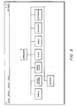
- a generalized example of this tree structure is shown in Figure 2 of the drawings. If a subassembly appears more than one time in a product, the subassembly also appears multiple times in the tree.
- the tree structure has three levels. It may have as few as two levels and, within practical limits, an indefinite number of levels depending on the product and the level of detail required to define that product. In a specific embodiment of the invention, up to thirty levels of the tree structure are allowed. Experience indicated that this is sufficient for all but the most complex of products.
- block 1 in Figure 2 would contain the legend "LAWNMOWER". This block would be generated immediately upon the entry of the word "LAWNMOWER" by the user 14. Then, as the user enters the names of the major components of the lawnmower, block 2 would be generated with the legend "FRAME ASSEMBLY”, block 3 would be generated with the legend "ENGINE”, block 4 would be generated with the legend "BAGGING ASSEMBLY”, and block 5 would be generated with the legend "HANDLE AND CONTROL ASSEMBLY". As these blocks are generated, lines connecting them to block 1 are also generated.
- Block 6 with the legend "ENGINE DECK” is generated followed by block 7 with the legend "WHEELS”, again with lines connecting these blocks to block 2. Since the engine is being purchased as a complete assembly and no subcomponents were entered by the user, there is no block under block 3. Blocks 8, 9 and 10 are then generated as the user enters subcomponent data in response to the query session.
- the database 10 captures the component information from the user input in a table having the form shown in Figure 3. Comparing this table to the hierarchical three of Figure 2, it will be observed that under the heading "ITEM" the numeral 1 is listed four times with the numerals 2, 3, 4, and 5 immediately to the right. This is followed by the numeral 2 listed twice with the numerals 6 and 7 immediately to the right.
- the table shown in Figure 3 directly describes the hierarchical three structure from which the graphical representation illustrated in Figure 2 is generated for display on the computer screen. The user views this tree structure and can check it for correctness as it is generated and after the product structure is established by the end of the query session.
- Figure 3 shows the logical storage of the product data structure and Figures 2 and 4 show two, alternative representations of the data.
- This bill of material is built by accessing the database table for the product. The table is accessed by item number. In the top level, item 1 is not indented.
- the second level items 2, 3, 4, and 5 are indented one space.
- the third level items 6, 7, 8, 9, and 10 are each indented two spaces, and so on.
- the application code follows the item hierarchy as follows: Item 1 appears on the top line. Item 2 appears on the second line. Then the database is searched for item 2 antecedents. Items 6 and 7 would be found. Item 6 would then appear on the third line. The database is then searched for item 6 antecedents. In this example, none would be found, and item 7 would then appear on the fourth line. Again, the database is searched for item 7 antecedents, but again non would be found, and item 3 would appear on the fifth line. The remaining items are similarly processed until a complete bill of material is produced.
- Figure 5 shows a concrete example of a hierarchical tree structure generated on the computer screen during the query process.
- the hierarchical tree structure may be displayed on several successive screens as the level of detail progresses.
- cost estimates can be drawn from the database 10. The user inputs a rough estimate on overall product assembly time in hours per unit, as well as a contingency factor, like 15%. The system decomposes the product structure into a parts list, which is the indented bill of materials.
- the quantity of each part as well as cost per part are pulled from the manufacturing information table in the relational database associated with each item.
- the cost estimating function then multiplies each part on the list by quantity of that part, then by cost of the part.
- the results for the parts list are added.
- the labor estimate is multiplied by the standard hourly labor and burden rate.
- the results of the parts list multiplication and the labor multiplication are added, and the result is output to the user.
- Figure 7 shows a screen from a computer display which would appear when the user selects, for example, BATTERY as the object and chooses the action "DETAIL".
- the design engineer keys in known manufacturing data using this screen.
- the designer intended to use an "off the shelf” battery to be purchased complete from Sears.
- the user can then choose to have default values supplied from the relational database based on known item attributes.
- the user selects the action "DEFAULT", and the screen shown in Figure 8 is displayed.
- the method by which the relational database can access these defaults is by accessing the table in which the user input data was captured during the query session.
- the attributes in the table are accessed by attribute numbers and these numbers, in turn, are used as an index to access the default attributes for the items, these values having been previously stored for similar parts in the database.
- the screen shown in Figure 7 displays the resultant default values, marked by an asterisk.
- the system has generated an item number, A000. From the position of the item within the tree, the system has determined that it is a Main Assembly. The full name of the vendor, Sears Roebuck, Inc., is inserted. The process by which the battery is incorporated into the product is assembly. Tooling lead time defaults to zero since the item is purchased complete off the shelf. The cost per battery, based on actuals, is 15.00.
- An item classification, or group technology classification is system generated based on the gathered attributes, function, sourcing strategy and vendor. This item classification code can be used in many production planning functions, including scheduling and procurement.
- FIG 8 there is shown a flow chart of the logic of the conceptual design tool implemented in software.
- One of ordinary skill in the art can write source code from this flow chart in any suitable computer language, such as BASIC, Pascal or C, for any desired computer system, such as the IBM Personal System (PS) computers which support those computer languages.
- suitable computer language such as BASIC, Pascal or C
- PS IBM Personal System
- the process begins by inputting the functional structure of the product as indicated by function block 100. This is done during the query session as is described in more detail with respect to Figure 9.
- the user is prompted to select an item in the structure in function block 102.
- the system provides a pop-up panel for manufacturing details in function block 104. This pop-up panel allows the user to key in known manufacturing information in function block 106.
- the system When this information has been input by the user, the system generates an item number in function block 108.
- the system then allows the user to choose to access default information in function block 110.
- a test is made in decision block 112 to determine if the user has chosen to access default information. If not, a test is next made in decision block 114 to determine if there are more items for which manufacturing details are to be input. If so, then the process loops back to function block 102.
- test in decision block 112 is positive, that is, the user chooses to access default information
- function block 116 the system accesses the default values in database 10 and inserts those values.
- function block 118 the system generates an item classification code.
- the user is given the option of overriding any of the default data in function block 120.
- a test is made in decision block 122 to determine if the user chooses to override any default data. If so, the system loops back to function block 106 which allows the user to key in known manufacturing data as a typeover of the previously inserted default data; otherwise, the system loops to function block 102 to select the next item in the functional structure of the product.
- the test in decision block 114 will be negative, and the process ends.
- Figure 9 shows in flow chart form the logic of the query system according to the invention.
- the program logic represented by Figure 9 is what builds the database represented by Figure 3.
- This flow chart in combination with a dialog system, such as IBM's REXX language, and a database system, such as IBM's DB2, is sufficient for a programmer of ordinary skill in the art to write the required code to implement the query system.
- the user of the system is prompted for the product name. In the example given, the name would be "LAWNMOWER".
- the system waits for a user input at decision block 24, and when the product name has been input, the system opens a file in the database with the product name and displays the product name on a computer screen in function block 26.
- l is set to l+1 indicating the next level of components, and the system then prompts the user in function block 30 for the components of the product at this level.
- the inputted component is stored in the data base for that level in function block 34, and the system displays the inputted component on the computer screen at a node of the tree structure in function block 36.
- the system will continue to prompt the user for components after each component is entered by the user until the user presses an END function key which signals an end to the list of components for this level.
- the system tests the user input in decision block 38 for the END function key input. If that key input is not detected, then the system waits for the next user input in decision block 32, and when an input is received, the component is stored in the database table in function block 34 and so forth.
- the system determines in decision block 40 if the last component in the current level of components has been input by the user. If not, the next component in the current level is highlighted in the displayed tree structure, and the system loops back to function block 30 where the user is again prompted for components of this component. On the other hand, if the last component of the current level of components has been input by the user as detected in decision block 40, the system tests for a user input in decision block 44 to determine if components are to be entered for the next level. This is accomplished by the user pressing a Y key or an N key when prompted for the next level.
- the system loops back to block 28 to index to the next level. If on the other hand, the N key is pressed indicating that the user does not at this time wish to input the next level of components or that there is no next level of components to enter, the query process ends.
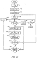
- FIG. 10 shows how the intended bill of materials is automatically generated from the table in the database which was built during the query session.
- this flow chart shows the logic of the automatic generation of the indented bill of materials, and any programmer skilled in the art with an understanding of database systems, such as the IBM DB2 database, can write code to implement the invention from the logic of the flow chart.
- item 1 of level 1 is accessed in function block 48. In the example given, this item is the product name "LAWNMOWER".
- Item 1 is then printed in function block 50, and l and i are then indexed by adding 1 to each.
- a test is then made in decision block 54 to determine if any level l is left in the tree. If so, the system accesses the next left-most item in the three of the current level in function block 56. The accessed item is then printed in function block 58 with indentation i.
- a search is then made of the data base in function block 60 for antecedents. If any are found in decision block 62, the system loops back to block 52 where the level and indentation are indexed by one. Otherwise, a test is made in decision block 64 to determine if the last item of the current level has been connected.
- the level and the indentation are indexed backward in block 66 by subtracting one from each.
- the process then returns to decision block 54 to continue the process of accessing and printing items in order.
- the level and indentation are again indexed backward by subtracting one in block 68.
- a test is then made in decision block 70 to determine if the indentation i is less than or equal to zero. If not, the process loops back to decision block 45; otherwise, the indented bill of materials is complete and the process ends.
- Figure 11 shows the product "LAWNMOWER” and a first major component “HANDLE” with two of its subcomponents “UPPER HANDLE” and “LOWER HANDLE” displayed in a simple tree structure.
- This tree represents three levels in terms of the logic illustrated by the flow charts of Figures 9 and 10.
- Figure 12 the user has input the components of a fourth level for the subcomponent "UPPER HANDLE”. From these two illustrations, it will be apparent the manner in which each component level is built by user input to the system.
- FIG 13 the indented bill of materials for the handle assembly of the lawnmower is shown as it appears on the computer screen. Note that the bill of material may be scrolled up or down by the cursor keys as indicated in order to display the complete bill of material as generated from the data base.
- the next stage in the process is to input the data gathered by the conceptual design tool to a project management tool.
- the preferred embodiment of the invention provides and interface between the conceptual design tool and the Management and Project Planning System (MAPPS) project management tool published by Mitchell Management Systems, Inc.
- MAPPS Management and Project Planning System
- This program includes two utility programs called MAPPOUT and MAPPIN.
- MAPPOUT enables the user to access network data contained in MAPPS networks by taking the interlocking MAPPS network data files and by putting that information into ASCII format.
- the restructuring essentially unlocks the files, separates the MAPPS network data, and makes it accessible to create new report formats or to recombine it with data from other programs.
- MAPPIN allows the user to extract data from other programs and to incorporate it into MAPPS.
- MAPPIN is an interface that enables data from another program to be inserted directly into MAPPS network data files.
- MAPPS project management tool is used in the preferred embodiment of the invention and represents the best mode of practicing the invention, those skilled in the art will appreciate that other project management tools with similar capability and function could be adapted for use in the practice of the invention.
- the information available from the conceptual design tool includes the technology required to produce the item, item type, item classification code, procurement source, lead time to design the item, lead time to simulate the time (if required), lead time to prototype the item, lead time to provide tooling to make the item (if required), time to release the item from engineering to manufacturing, lead time to procure the item (if required), time to transport the item from vendor (if required), time to inspect the item (if required), and time to retrieve the item (if required).
- Project management techniques are used to schedule product release.
- the user submits a product structure which also carries manufacturing detail for each item for a product release schedule. Items within the structure for which there are missing lead times are highlighted, although missing lead times may be defaulted to standard default time if the user does not override.
- the user reviews the application profile, and restricted update of the release planning assumptions can be done.
- DEFINITION OF ITEM CRITICALITY function the user can modify the rules which determine whether an item is critical. Only critical items within the product structure are sent to the project management tool. Criticality factors include item cost, item procurement and tooling lead times, and new technology factors. Assumptions also include forward and backward project scheduling, and a project completion date if backward scheduling is chosen.
- Time unit of measure either days or weeks.
- Design time for the average part in the assembly Unusual design times are specified in the manufacturing detail. The number of designers as resources for the project is also required. Simulation time per part. The number of simulators available as resources for the product is also required. If the same people do both design and simulation, a proportional amount of resource should be allocated to both activities.
- Prototyping time per part The number of prototyping resources available for this product is required. If the same people do both design, prototyping and simulation, a proportional amount of resource should be allocated to each of the three activities.
- Default tooling time per part (if the user did not indicate a time within the manufacturing detail information, the default will be used rather than non information at all). If tooling resource can be capacitating, the number of tooling resources should be specified. Default time to release an item from engineering to manufacturing. Default procurement time per part. Default transportation time per part. Default inspection time per part. Default retrieval from stores time per part.
- Default assembly time (the default time may be zero, since assembly time typically is much smaller than any other time considerations).
- the holiday schedule of employees assigned to the product must be verified.
- the product structure is decomposed into a part list by the system, as has already been described.
- DEFINITION OF ITEM CRITICALITY function is invoked, and based on the user's chosen factors, the parts list is modified. All manufacturing detail information on each part on the list is passed to this function. Items which are not critical are eliminated from the list using the DEFINITION OF ITEM CRITICALITY function.
- the system then invokes the RELEASE PROJECT MANAGEMENT function.
- the critical parts list and corresponding lead time information are passed to the project manager. Each part requires a certain zero or non-zero amount of unit time for design, simulation, prototyping, tooling, procurement, transportation, inspection, retrieval from stores, product preanalysis, and formal release.
- the RELEASE PLAN PROJECT MANAGEMENT function operates in either forward or backward scheduling mode.
- forward scheduling mode each item has a series of time and resource consuming events associated with it.
- the user does not determine the first customer ship date for the product until the project manager has completed the release schedule.
- the project manager needs to select the longest lead time item, and schedule it first. Any resources consumed are subtracted from available resource.
- the project manager continues to select long lead time items, until all are scheduled. Resources will not be overallocated, as the first customer ship date will be pushed out for both time and resource reasons.
- Backward scheduling involves choosing the first customer ship date and working backward to fit all required activities in prior to that date. During this process, available resources may be overallocated.
- the project manager needs to highlight that fact to the user, but continue the scheduling process, as the user may be able to get additional resource if the need arises.
- a detailed product schedule by item is then produced, for all critical items.
- the procedure described may be iterative with both product structuring and cost estimating.
- the user then needs to create engineering changes to implement the product release. That process begins with the detailed product schedule with release dates for each critical item within the product.
- the user requests engineering changes bundling and inputs the desired frequency for engineering change package releases. Frequencies would typically be one per month or two week periods.
- An engineering change number for each engineering change release is then generated by the system.
- the system determines the release date for each item in the release schedule. These dates are grouped into the time periods as defined by the user.
- EC NUMBER ASSIGNMENT function is invoked to system generate an engineering change number for each engineering change release required.
- Figures 14A, 14B and 14C which, taken together, form a flow chart of the automated interface to the project management tool.
- the logic depicted in this flow chart is sufficient for a programmer of ordinary skill in the art to write source code in a high level language such as BASIC, Pascal or C to implement the invention.
- the process begins in Figure 14A where, in function block 200, the conceptual design tool is used to build and modify the product structure. This process was described with reference to Figure 9.
- function block 202 the conceptual design tool is used to input manufacturing details by item in the structure. This process was described with reference to Figures 6, 7 and 8. At this point, the user can request the generation of a release schedule, as indicated in function block 204.
- the project management interface When the user requests the generation of a release schedule, the project management interface according to the present invention is invoked in function block 206.
- the manner in which the data files generated by de conceptual design tool are formatted for the project management tool is described in detail with reference to Figures 15A to 15E.
- the user is next asked in decision block 208 whether forward or backward scheduling is desired. If forward scheduling is chosen by the user, the user is prompted to fill in the start date in block 210, but if backward scheduling is chosen, the user is prompted to fill in the first customer ship date in block 212.
- Control then goes to decision block 214 at the top of Figure 14B where the user is given the option to update the application profile defaults.
- the profiled defaults are automatically inserted by the system, and the user can elect to use the defaults or change them. If the user chooses to update the defaults, then in function block 216 the user can key in new values by typing over the those default values the user wants to update. The process then goes to decision block 218 where again the user is given the option of updating the system data, this time the definition of criticality. If the user chooses to update, then in function block 220 the user can key in new definitions by typing over those the user wants to update.
- the system selects items which fulfill criticality requirements in blocks 222, 223 and 224 to produce a list of selected items in block 226.
- the preferred database is IBM's DB2.
- the lead times for each item in the list produced in block 226 are added to produce in block 232 at the top of Figure 14C a list of all items and associated lead times.
- the system extracts additional lead times from the application profile in block 234 and these lead times are added for each item in block 236.
- the system finds the longest lead time in the list in function block 238. All events with associated lead times are defined as activities in function block 240, and the activities for the item are listed in function block 242.
- a determination is made in decision block 244 whether there are more items to process in the list. If there are, control loops back to function block 238 where the next longest lead time item is found and so on. Once the last item has been processed, the files are formatted for the project management tool in function block 246.
- FIG. 15A The process of formatting the files for the project management tool, here the MAPPS project management tool, is shown in Figures 15A to 15E.
- the process begins in Figure 15A by calling a MAPPS network data file shell in function block 250. This is an empty data file with no activities or resources. Then, in function block 252, the name of the project is printed in the file shell. This name is the conceptual design tool product name. A check is made in decision block 254 to determine if the name is valid and, if not, an error message is displayed in block 256 before control returns to block 252. Assuming a valid name has been printed to the file, the header information for the file is printed in function block 258. Checks of each of the numbers of activities, resources, connectors, and milestones are checked in function block 260, and if any fail as determined by decision block 261, an error message is displayed before control returns to function block 260.
- the next step in the process is to print the activities file, as shown in block 264 at the top of Figure 15B.
- the data field option is set equal to APPEND in block 266, and the process of printing activity numbers begins in block 268. Each activity number is followed by printing the activity details to the file in block 270. A logical check is made in block 271 before a determination is made in decision block 272 as to whether there are more activities to be printed to the file.
- the resources file is printed to the file in block 274.
- the data field option is set equal to APPEND in block 276, and the process of printing resource sequence file number begins in block 278. After each resource file number, the resource detail is printed to the file in block 280.
- a logical check is made in block 281 before a determination is made in decision block 282 as to whether there are more resources to be printed to the file.
- the time and cost information is printed in function block 284.
- the activity number is verified in block 286, and the time and cost detail is printed to the file in block 288. This process continues until a determination is made in decision block 289 that all activities have been processed.
- the activity resource usage is then printed to the file in function block 290.
- the activity number is again verified in block 292, and the activity, resource number and usage detail is printed to the file in block 294. This process continues until a determination is made in decision block 295 that all activities have been processed.
- the activity milestones are printed to the file in function block 296. in function block 298 at the top of Figure 15D, the milestones are printed followed by the date in block 300. As this is done, the activity numbers are verified in block 302. This process continues until all milestones have been processed as determined by decision block 303.
- the connector information is formatted next.
- the activities for the several item numbers are selected, and then in block 306 the activities are ordered according to date.
- the connector file is printed to the file in block 308.
- the activity is printed in block 310 until all activities have been processed as determined by decision block 311.
- the from/to relationship, that is the connector information, is specified in block 312 until all items have been processed as determined by decision block 314.
- the automatic transfer of information required to generate a release schedule is a major usability and productivity enhancement over existing semi-manual project management systems. It utilizes available information, knowledge and interrelationship previously gathered through other required phases of planning the product release plus user interactivity to produce a product release activity sequence and schedule.
Landscapes
- Engineering & Computer Science (AREA)
- Business, Economics & Management (AREA)
- Theoretical Computer Science (AREA)
- Physics & Mathematics (AREA)
- Economics (AREA)
- Strategic Management (AREA)
- General Physics & Mathematics (AREA)
- Entrepreneurship & Innovation (AREA)
- Human Resources & Organizations (AREA)
- Tourism & Hospitality (AREA)
- Quality & Reliability (AREA)
- Operations Research (AREA)
- Marketing (AREA)
- Development Economics (AREA)
- General Business, Economics & Management (AREA)
- Game Theory and Decision Science (AREA)
- Accounting & Taxation (AREA)
- Educational Administration (AREA)
- Finance (AREA)
- Computer Hardware Design (AREA)
- Evolutionary Computation (AREA)
- Geometry (AREA)
- General Engineering & Computer Science (AREA)
- Management, Administration, Business Operations System, And Electronic Commerce (AREA)
- General Factory Administration (AREA)
- Control By Computers (AREA)
- Multi-Process Working Machines And Systems (AREA)
Applications Claiming Priority (2)
| Application Number | Priority Date | Filing Date | Title |
|---|---|---|---|
| US115073 | 1987-10-28 | ||
| US07/115,073 US4875162A (en) | 1987-10-28 | 1987-10-28 | Automated interfacing of design/engineering software with project management software |
Publications (3)
| Publication Number | Publication Date |
|---|---|
| EP0314596A2 true EP0314596A2 (fr) | 1989-05-03 |
| EP0314596A3 EP0314596A3 (fr) | 1991-01-16 |
| EP0314596B1 EP0314596B1 (fr) | 1997-04-23 |
Family
ID=22359157
Family Applications (1)
| Application Number | Title | Priority Date | Filing Date |
|---|---|---|---|
| EP88480035A Expired - Lifetime EP0314596B1 (fr) | 1987-10-28 | 1988-09-13 | Interface à un outil de gestion de projet |
Country Status (6)
| Country | Link |
|---|---|
| US (1) | US4875162A (fr) |
| EP (1) | EP0314596B1 (fr) |
| JP (1) | JP2509309B2 (fr) |
| BR (1) | BR8805536A (fr) |
| CA (1) | CA1286406C (fr) |
| DE (1) | DE3855886D1 (fr) |
Cited By (11)
| Publication number | Priority date | Publication date | Assignee | Title |
|---|---|---|---|---|
| FR2661017A1 (fr) * | 1990-04-13 | 1991-10-18 | Fricot Serge | Systeme de controle de processus industriel. |
| EP0520923A2 (fr) * | 1991-06-28 | 1992-12-30 | International Business Machines Corporation | Procédé et système de définition et poursuite de la configuration d'un produit |
| WO1995012174A1 (fr) * | 1993-10-27 | 1995-05-04 | Logical Water Limited | Systeme et procede de definition d'une structure de traitement destinee a l'execution d'une tache |
| WO2000060510A1 (fr) * | 1999-04-06 | 2000-10-12 | Single Source Oy | Mecanisme de gestion de donnees pour planification de projet |
| GB2369460A (en) * | 2000-09-29 | 2002-05-29 | Reservoirteam Ltd | Knowledge based project management system |
| EP1277153A1 (fr) * | 2000-03-31 | 2003-01-22 | Siebel Systems, Inc. | Procede et systeme de gestion d'edition centrale de caracteristiques |
| EP1284465A2 (fr) * | 2001-07-19 | 2003-02-19 | Toyota Caelum Incorporated | Système d'aide de gestion de tâches |
| WO2003079185A2 (fr) * | 2002-03-18 | 2003-09-25 | Aes Engineering Ltd | Application integree de selection de produit, d'information commerciale sur le produit, et de dessin donnant une representation generale du produit |
| WO2003096131A1 (fr) | 2002-04-10 | 2003-11-20 | Toyota Jidosha Kabushiki Kaisha | Systeme et procede d'assistance a la detection de problemes dans un systeme de fourniture de pieces et programme associe |
| WO2004081682A1 (fr) * | 2003-03-14 | 2004-09-23 | Avl List Gmbh | Procede pour concevoir et construire des produits techniques complexes |
| AT501214B1 (de) * | 2003-03-14 | 2008-11-15 | Avl List Gmbh | Verfahren zur auslegung und konstruktion von komplexen technischen produkten |
Families Citing this family (116)
| Publication number | Priority date | Publication date | Assignee | Title |
|---|---|---|---|---|
| US5089970A (en) * | 1989-10-05 | 1992-02-18 | Combustion Engineering, Inc. | Integrated manufacturing system |
| JP2642491B2 (ja) * | 1989-10-25 | 1997-08-20 | 株式会社日立製作所 | 商品仕様決定方法、並びに商品仕様決定見積方法とその装置 |
| JPH04195461A (ja) * | 1990-11-28 | 1992-07-15 | Hitachi Ltd | 日程表作成システム |
| JPH0644255A (ja) * | 1991-05-17 | 1994-02-18 | Shimizu Corp | 統合的生産プロジェクト情報管理システム |
| US5307261A (en) * | 1991-06-28 | 1994-04-26 | International Business Machines Corporation | Method and system for product configuration management in a computer based manufacturing system |
| US5293479A (en) * | 1991-07-08 | 1994-03-08 | Quintero Smith Incorporated | Design tool and method for preparing parametric assemblies |
| US5260866A (en) * | 1991-09-17 | 1993-11-09 | Andersen Consulting | Expert configurator |
| US5381332A (en) * | 1991-12-09 | 1995-01-10 | Motorola, Inc. | Project management system with automated schedule and cost integration |
| US5535322A (en) * | 1992-10-27 | 1996-07-09 | International Business Machines Corporation | Data processing system with improved work flow system and method |
| WO1994020918A1 (fr) * | 1993-03-11 | 1994-09-15 | Fibercraft/Descon Engineering, Inc. | Systeme de gestion de projet d'etude et d'ingenierie |
| JPH06325110A (ja) * | 1993-05-17 | 1994-11-25 | Nec Corp | 板金cadシステム |
| US5548506A (en) * | 1994-03-17 | 1996-08-20 | Srinivasan; Seshan R. | Automated, electronic network based, project management server system, for managing multiple work-groups |
| US5655118A (en) * | 1994-03-21 | 1997-08-05 | Bell Communications Research, Inc. | Methods and apparatus for managing information on activities of an enterprise |
| US5790847A (en) * | 1994-05-23 | 1998-08-04 | International Business Machines Corporation | Integration of groupware with activity based management via facilitated work sessions |
| US5500802A (en) * | 1994-05-31 | 1996-03-19 | Morris; James M. | System and method for creating configurators using templates |
| US5646862A (en) * | 1994-09-29 | 1997-07-08 | Ford Motor Company | Vendor-neutral integrated vehicle electrical design and analysis system and method |
| US6397262B1 (en) | 1994-10-14 | 2002-05-28 | Qnx Software Systems, Ltd. | Window kernel |
| US5745759A (en) * | 1994-10-14 | 1998-04-28 | Qnx Software Systems, Ltd. | Window kernel |
| US5675784A (en) * | 1995-05-31 | 1997-10-07 | International Business Machnes Corporation | Data structure for a relational database system for collecting component and specification level data related to products |
| US5748943A (en) * | 1995-10-04 | 1998-05-05 | Ford Global Technologies, Inc. | Intelligent CAD process |
| US5893074A (en) * | 1996-01-29 | 1999-04-06 | California Institute Of Technology | Network based task management |
| US5765137A (en) * | 1996-03-04 | 1998-06-09 | Massachusetts Institute Of Technology | Computer system and computer-implemented process for correlating product requirements to manufacturing cost |
| US5793632A (en) * | 1996-03-26 | 1998-08-11 | Lockheed Martin Corporation | Cost estimating system using parametric estimating and providing a split of labor and material costs |
| US6006195A (en) * | 1996-04-26 | 1999-12-21 | Workgroup Technology Corporation | Product development system and method using integrated process and data management |
| US5754738A (en) * | 1996-06-07 | 1998-05-19 | Camc Corporation | Computerized prototyping system employing virtual system design enviroment |
| US5950206A (en) * | 1997-04-23 | 1999-09-07 | Krause; Gary Matthew | Method and apparatus for searching and tracking construction projects in a document information database |
| JP3938221B2 (ja) * | 1997-06-04 | 2007-06-27 | 本田技研工業株式会社 | 工程情報管理システム |
| AU8160098A (en) | 1997-06-23 | 1999-01-04 | Construction Specifications Institute, The | Method and apparatus for computer aided building specification generation |
| JPH1115646A (ja) * | 1997-06-25 | 1999-01-22 | Fujitsu Ltd | 技術情報管理システム |
| JPH1185860A (ja) * | 1997-09-10 | 1999-03-30 | Hitachi Ltd | 部品発注期限自動管理システム |
| US6961687B1 (en) * | 1999-08-03 | 2005-11-01 | Lockheed Martin Corporation | Internet based product data management (PDM) system |
| US6959268B1 (en) * | 1999-09-21 | 2005-10-25 | Lockheed Martin Corporation | Product catalog for use in a collaborative engineering environment and method for using same |
| US7146608B1 (en) * | 1999-09-28 | 2006-12-05 | Cisco Technology, Inc. | Method and system for a software release process |
| US6684191B1 (en) | 1999-11-22 | 2004-01-27 | International Business Machines Corporation | System and method for assessing a procurement and accounts payable system |
| US6738746B1 (en) | 1999-11-22 | 2004-05-18 | International Business Machines Corporation | System and method for ongoing supporting a procurement and accounts payable system |
| US6714915B1 (en) * | 1999-11-22 | 2004-03-30 | International Business Machines Corporation | System and method for project designing and developing a procurement and accounts payable system |
| US7437304B2 (en) * | 1999-11-22 | 2008-10-14 | International Business Machines Corporation | System and method for project preparing a procurement and accounts payable system |
| US6687677B1 (en) | 1999-11-22 | 2004-02-03 | International Business Machines Corporation | System and method for deploying a procurement and accounts payable system |
| US6604237B1 (en) * | 1999-12-14 | 2003-08-05 | International Business Machines Corporation | Apparatus for journaling during software deployment and method therefor |
| US6983278B1 (en) | 2001-04-10 | 2006-01-03 | Arena Solutions, Inc. | System and method for access control and for supply chain management via a shared bill of material |
| US7558793B1 (en) | 2000-04-10 | 2009-07-07 | Arena Solutions, Inc. | System and method for managing data in multiple bills of material over a network |
| US6842760B1 (en) | 2000-05-03 | 2005-01-11 | Chad Barry Dorgan | Methods and apparata for highly automated quality assurance of building construction projects |
| US20020099524A1 (en) * | 2000-05-31 | 2002-07-25 | 3M Innovative Properties Company | Process and system for designing a customized artistic element package |
| US7231356B1 (en) * | 2000-07-10 | 2007-06-12 | The United States Of America As Represented By The Secretary Of The Navy | Operating plan for machinery |
| US20020052770A1 (en) * | 2000-10-31 | 2002-05-02 | Podrazhansky Mikhail Yury | System architecture for scheduling and product management |
| US7043408B2 (en) | 2000-11-08 | 2006-05-09 | Virtual Supply Chain Engineering, Inc. | Computer-aided design neutral graphical data interface |
| US20020111850A1 (en) * | 2001-02-12 | 2002-08-15 | Chevron Oronite Company Llc | System and method for new product clearance and development |
| US20060010081A1 (en) * | 2001-03-01 | 2006-01-12 | Williams Charles W | Automated system for assisting the architectural process |
| US8578262B2 (en) * | 2002-03-01 | 2013-11-05 | Charles W. Williams | Cad-interfaced, automated system for assisting the architectural process |
| WO2002073473A1 (fr) * | 2001-03-13 | 2002-09-19 | Bombardier Inc. | Systeme et procede pour la configuration de l'architecture interieure d'un vehicule |
| US6999965B1 (en) * | 2001-04-10 | 2006-02-14 | Arena Solutions, Inc. | Method, apparatus, and product to associate computer aided design data and bill of materials data |
| WO2002088944A1 (fr) * | 2001-05-01 | 2002-11-07 | Tonbu, Inc. | Systeme et procede interactifs et collaboratifs de gestion de processus et de projet |
| US7191141B2 (en) * | 2001-06-13 | 2007-03-13 | Ricoh Company, Ltd. | Automated management of development project files over a network |
| US7406432B1 (en) | 2001-06-13 | 2008-07-29 | Ricoh Company, Ltd. | Project management over a network with automated task schedule update |
| TW509862B (en) * | 2001-07-25 | 2002-11-11 | Elite Intelligence Corp | Method for self-defining part number |
| US20030033158A1 (en) * | 2001-08-09 | 2003-02-13 | Electronic Data Systems Corporation | Method and system for determining service resources allocation |
| US8407325B2 (en) * | 2001-08-23 | 2013-03-26 | International Business Machines Corporation | Method and system for automated project accountability |
| JP4369082B2 (ja) * | 2001-10-05 | 2009-11-18 | 株式会社日立製作所 | 部品選択支援システム、部品選択支援方法、部品選択支援プログラムおよび部品選択支援記憶媒体 |
| US7212987B2 (en) * | 2001-10-23 | 2007-05-01 | International Business Machines Corporation | System and method for planning a design project, coordinating project resources and tools and monitoring project progress |
| US20030130749A1 (en) * | 2001-11-07 | 2003-07-10 | Albert Haag | Multi-purpose configuration model |
| US20040010772A1 (en) * | 2001-11-13 | 2004-01-15 | General Electric Company | Interactive method and system for faciliting the development of computer software applications |
| US8935297B2 (en) * | 2001-12-10 | 2015-01-13 | Patrick J. Coyne | Method and system for the management of professional services project information |
| US7437688B2 (en) * | 2001-12-27 | 2008-10-14 | Caterpillar Inc. | Element routing method and apparatus |
| US20030135401A1 (en) * | 2002-01-14 | 2003-07-17 | Parr Ian Barry Anthony | Method and process of program management for the owner's representative of design-build construction projects |
| JP2003216844A (ja) * | 2002-01-24 | 2003-07-31 | Toyota Industries Corp | 生産準備を管理する装置およびその方法 |
| US6760640B2 (en) * | 2002-03-14 | 2004-07-06 | Photronics, Inc. | Automated manufacturing system and method for processing photomasks |
| US7640529B2 (en) * | 2002-07-30 | 2009-12-29 | Photronics, Inc. | User-friendly rule-based system and method for automatically generating photomask orders |
| US7669167B2 (en) * | 2002-07-30 | 2010-02-23 | Photronics, Inc. | Rule based system and method for automatically generating photomask orders by conditioning information from a customer's computer system |
| US6842881B2 (en) * | 2002-07-30 | 2005-01-11 | Photronics, Inc. | Rule based system and method for automatically generating photomask orders in a specified order format |
| US20030182167A1 (en) * | 2002-03-21 | 2003-09-25 | Wolfgang Kalthoff | Goal management |
| US7286999B2 (en) * | 2002-05-09 | 2007-10-23 | International Business Machines Corporation | Integrated project management and development environment for determining the time expended on project tasks |
| US7386797B1 (en) * | 2002-05-22 | 2008-06-10 | Oracle Corporation | Framework to model and execute business processes within a collaborative environment |
| US20030233268A1 (en) * | 2002-06-17 | 2003-12-18 | Ehsan Taqbeem | Multi-dimensional interdependency based project management |
| DE10235517A1 (de) * | 2002-08-05 | 2004-03-04 | Siemens Ag | Werkzeug und Verfahren zum Projektieren, Auslegen oder Programmieren einer Anlage |
| US7159206B1 (en) * | 2002-11-26 | 2007-01-02 | Unisys Corporation | Automated process execution for project management |
| US7302674B1 (en) * | 2002-11-26 | 2007-11-27 | Unisys Corporation | Automating document reviews in a project management system |
| US7171652B2 (en) * | 2002-12-06 | 2007-01-30 | Ricoh Company, Ltd. | Software development environment with design specification verification tool |
| US20080147467A1 (en) * | 2003-06-30 | 2008-06-19 | Daum Andreas W | Configuration Process Scheduling |
| JP4970711B2 (ja) * | 2003-07-07 | 2012-07-11 | ハイデルベルガー ドルツクマシーネン アクチエンゲゼルシヤフト | 製造工程を見出す方法 |
| US20050038553A1 (en) * | 2003-08-15 | 2005-02-17 | York International Corporation | System and method for managing the production of a custom designed product |
| US7308675B2 (en) * | 2003-08-28 | 2007-12-11 | Ricoh Company, Ltd. | Data structure used for directory structure navigation in a skeleton code creation tool |
| US7237224B1 (en) * | 2003-08-28 | 2007-06-26 | Ricoh Company Ltd. | Data structure used for skeleton function of a class in a skeleton code creation tool |
| US7685103B2 (en) * | 2003-09-29 | 2010-03-23 | International Business Machines Corporation | Method, system, and program for predicate processing by iterator functions |
| US7103434B2 (en) * | 2003-10-14 | 2006-09-05 | Chernyak Alex H | PLM-supportive CAD-CAM tool for interoperative electrical and mechanical design for hardware electrical systems |
| US7930149B2 (en) * | 2003-12-19 | 2011-04-19 | Sap Aktiengesellschaft | Versioning of elements in a configuration model |
| US7610549B2 (en) * | 2004-05-20 | 2009-10-27 | Sap Ag | Method and system for Java Gantt/bar chart rendering |
| WO2006007447A2 (fr) * | 2004-06-17 | 2006-01-19 | Kinaxis Inc. | Systeme de programmation |
| US20060089865A1 (en) * | 2004-10-25 | 2006-04-27 | Mcnulty Hicken Smith, Inc. | Computer-aided method for managing a part shipping apparatus development project |
| US20060122724A1 (en) * | 2004-12-07 | 2006-06-08 | Photoronics, Inc. 15 Secor Road P.O. Box 5226 Brookfield, Connecticut 06804 | System and method for automatically generating a tooling specification using a logical operations utility that can be used to generate a photomask order |
| US20060129270A1 (en) * | 2004-12-10 | 2006-06-15 | Gerold Pankl | Processes and systems for creation of machine control for specialty machines requiring manual input |
| US20060129461A1 (en) * | 2004-12-10 | 2006-06-15 | Gerold Pankl | Data entry and system for automated order, design, and manufacture of ordered parts |
| US20070005167A1 (en) * | 2005-06-30 | 2007-01-04 | George Roumeliotis | System and method for pro-active manufacturing performance management |
| US20070022126A1 (en) * | 2005-07-21 | 2007-01-25 | Caterpillar Inc. | Method and apparatus for updating an asset catalog |
| US20070022028A1 (en) * | 2005-07-21 | 2007-01-25 | Caterpillar Inc. | System design tool according to reusable asset specifications |
| JP4970450B2 (ja) * | 2005-08-10 | 2012-07-04 | イーアーファウ ゲーエムベーハー インジュニアゲゼルシャフト アオト ウント フェアケア | 製品の創作、設計、管理、スケジューリング、開発、及び製造 |
| US20070088589A1 (en) * | 2005-10-17 | 2007-04-19 | International Business Machines Corporation | Method and system for assessing automation package readiness and and effort for completion |
| US20060184402A1 (en) * | 2005-12-07 | 2006-08-17 | BIll Fuchs | Hospitality Analytics |
| US8050953B2 (en) * | 2006-06-07 | 2011-11-01 | Ricoh Company, Ltd. | Use of a database in a network-based project schedule management system |
| US8799043B2 (en) | 2006-06-07 | 2014-08-05 | Ricoh Company, Ltd. | Consolidation of member schedules with a project schedule in a network-based management system |
| US20070288288A1 (en) * | 2006-06-07 | 2007-12-13 | Tetsuro Motoyama | Use of schedule editors in a network-based project schedule management system |
| US20090006147A1 (en) * | 2007-06-27 | 2009-01-01 | Harirajan Padmanabhan | Method and system for defining and managing information technology projects based on conceptual models |
| JP5044820B2 (ja) * | 2008-01-24 | 2012-10-10 | インターナショナル・ビジネス・マシーンズ・コーポレーション | 工程管理を行うシステム、工程管理方法およびプログラム |
| US20090234702A1 (en) * | 2008-03-12 | 2009-09-17 | Chester James S | Method of process control for widely distributed manufacturing processes |
| JP2010108321A (ja) * | 2008-10-31 | 2010-05-13 | Hitachi-Ge Nuclear Energy Ltd | 建設状況可視化システム |
| US20100312373A1 (en) * | 2009-06-04 | 2010-12-09 | Thales | Method and system to design standard basic elements |
| CN101645011B (zh) * | 2009-07-16 | 2013-07-31 | 唐山轨道客车有限责任公司 | 异构的工作组协同设计系统与plm系统的集成方案和平台 |
| US8086337B1 (en) | 2009-08-21 | 2011-12-27 | Honda Motor Co., Ltd. | Computerized system and method for generating a delivery bill of materials |
| US9582613B2 (en) * | 2011-11-23 | 2017-02-28 | Siemens Product Lifecycle Management Software Inc. | Massive model visualization with spatial retrieval |
| US20150127402A1 (en) * | 2013-11-06 | 2015-05-07 | Giga-Byte Technology Co.,Ltd. | Method and system for structuring information background of the invention |
| US10402504B1 (en) | 2013-12-10 | 2019-09-03 | Enovation Controls, Llc | Time-saving and error-minimizing multiscopic hydraulic system design canvas |
| US10055703B2 (en) * | 2015-01-13 | 2018-08-21 | Accenture Global Services Limited | Factory management system |
| US20160275219A1 (en) * | 2015-03-20 | 2016-09-22 | Siemens Product Lifecycle Management Software Inc. | Simulating an industrial system |
| US10614632B2 (en) | 2015-04-23 | 2020-04-07 | Siemens Industry Software Inc. | Massive model visualization with a product lifecycle management system |
| US10325063B2 (en) | 2016-01-19 | 2019-06-18 | Ford Motor Company | Multi-valued decision diagram feature state determination |
| US11449813B2 (en) | 2018-04-13 | 2022-09-20 | Accenture Global Solutions Limited | Generating project deliverables using objects of a data model |
| US11257035B2 (en) * | 2018-09-10 | 2022-02-22 | Sap Se | Splitting a task hierarchy |
Citations (2)
| Publication number | Priority date | Publication date | Assignee | Title |
|---|---|---|---|---|
| US4459663A (en) * | 1981-07-02 | 1984-07-10 | American Business Computer | Data processing machine and method of allocating inventory stock for generating work orders for producing manufactured components |
| WO1985002699A1 (fr) * | 1983-12-09 | 1985-06-20 | Affiliated Innovation Management Inc. | Representation de graphiques structuraux |
-
1987
- 1987-10-28 US US07/115,073 patent/US4875162A/en not_active Expired - Fee Related
-
1988
- 1988-09-13 EP EP88480035A patent/EP0314596B1/fr not_active Expired - Lifetime
- 1988-09-13 DE DE3855886T patent/DE3855886D1/de not_active Expired - Lifetime
- 1988-09-15 CA CA000577521A patent/CA1286406C/fr not_active Expired - Fee Related
- 1988-09-20 JP JP23385088A patent/JP2509309B2/ja not_active Expired - Lifetime
- 1988-10-27 BR BR8805536A patent/BR8805536A/pt not_active Application Discontinuation
Patent Citations (2)
| Publication number | Priority date | Publication date | Assignee | Title |
|---|---|---|---|---|
| US4459663A (en) * | 1981-07-02 | 1984-07-10 | American Business Computer | Data processing machine and method of allocating inventory stock for generating work orders for producing manufactured components |
| WO1985002699A1 (fr) * | 1983-12-09 | 1985-06-20 | Affiliated Innovation Management Inc. | Representation de graphiques structuraux |
Non-Patent Citations (3)
| Title |
|---|
| CONTROL ENGINEERING, April 1971, pages 61-64; C.A. RENOUARD: "A computerized inventory model for production control" * |
| EXPERT DATABASE SYSTEMS, PROCEEDINGS FROM THE FIRST INTERNATIONAL WORKSHIP, 24th - 27th October 1984, pages 423-440, editor Larry Kershberg, US; S.J. CAMMARATA et al.: "An interactive data dictionary facility for CAD/CAM data bases" * |
| IEEE 1985 COMPINT - COMPUTER AIDED TECHNOLOGIES, Montreal, Quebec, 9th - 13th September 1985, pages 441-446; F. VERNADAT et al.: "CAD/CAM databases at NRC: from manufacturing cell database systems to engineering information systems" * |
Cited By (18)
| Publication number | Priority date | Publication date | Assignee | Title |
|---|---|---|---|---|
| FR2661017A1 (fr) * | 1990-04-13 | 1991-10-18 | Fricot Serge | Systeme de controle de processus industriel. |
| EP0520923A2 (fr) * | 1991-06-28 | 1992-12-30 | International Business Machines Corporation | Procédé et système de définition et poursuite de la configuration d'un produit |
| EP0520923A3 (fr) * | 1991-06-28 | 1995-01-11 | Ibm | |
| WO1995012174A1 (fr) * | 1993-10-27 | 1995-05-04 | Logical Water Limited | Systeme et procede de definition d'une structure de traitement destinee a l'execution d'une tache |
| AU687457B2 (en) * | 1993-10-27 | 1998-02-26 | Hyperknowledge Management Services Ag | A system and method for defining a process structure for performing a task |
| US6002396A (en) * | 1993-10-27 | 1999-12-14 | Davies; Trevor Bryan | System and method for defining a process structure for performing a task |
| WO2000060510A1 (fr) * | 1999-04-06 | 2000-10-12 | Single Source Oy | Mecanisme de gestion de donnees pour planification de projet |
| US7302401B1 (en) | 1999-04-06 | 2007-11-27 | Single Source Oy | Data management mechanism for project planning |
| EP1277153A1 (fr) * | 2000-03-31 | 2003-01-22 | Siebel Systems, Inc. | Procede et systeme de gestion d'edition centrale de caracteristiques |
| EP1277153A4 (fr) * | 2000-03-31 | 2005-12-07 | Siebel Systems Inc | Procede et systeme de gestion d'edition centrale de caracteristiques |
| GB2369460A (en) * | 2000-09-29 | 2002-05-29 | Reservoirteam Ltd | Knowledge based project management system |
| EP1284465A2 (fr) * | 2001-07-19 | 2003-02-19 | Toyota Caelum Incorporated | Système d'aide de gestion de tâches |
| EP1284465A3 (fr) * | 2001-07-19 | 2004-05-26 | Toyota Caelum Incorporated | Système d'aide de gestion de tâches |
| WO2003079185A2 (fr) * | 2002-03-18 | 2003-09-25 | Aes Engineering Ltd | Application integree de selection de produit, d'information commerciale sur le produit, et de dessin donnant une representation generale du produit |
| WO2003079185A3 (fr) * | 2002-03-18 | 2004-05-13 | Aes Eng Ltd | Application integree de selection de produit, d'information commerciale sur le produit, et de dessin donnant une representation generale du produit |
| WO2003096131A1 (fr) | 2002-04-10 | 2003-11-20 | Toyota Jidosha Kabushiki Kaisha | Systeme et procede d'assistance a la detection de problemes dans un systeme de fourniture de pieces et programme associe |
| WO2004081682A1 (fr) * | 2003-03-14 | 2004-09-23 | Avl List Gmbh | Procede pour concevoir et construire des produits techniques complexes |
| AT501214B1 (de) * | 2003-03-14 | 2008-11-15 | Avl List Gmbh | Verfahren zur auslegung und konstruktion von komplexen technischen produkten |
Also Published As
| Publication number | Publication date |
|---|---|
| EP0314596A3 (fr) | 1991-01-16 |
| BR8805536A (pt) | 1989-07-04 |
| JP2509309B2 (ja) | 1996-06-19 |
| DE3855886D1 (de) | 1997-05-28 |
| JPH01116765A (ja) | 1989-05-09 |
| US4875162A (en) | 1989-10-17 |
| CA1286406C (fr) | 1991-07-16 |
| EP0314596B1 (fr) | 1997-04-23 |
Similar Documents
| Publication | Publication Date | Title |
|---|---|---|
| US4875162A (en) | Automated interfacing of design/engineering software with project management software | |
| EP0314594B1 (fr) | Outil de conception | |
| EP0314595B1 (fr) | Interface de liste de matériel à un environnement CAD/CAM | |
| EP0309374B1 (fr) | Facturation automatisée de matériaux | |
| US6609100B2 (en) | Program planning management system | |
| Harmsen et al. | Situational method engineering for information system project approaches | |
| CN101111838B (zh) | 多维企业软件系统中的自动关系模式生成 | |
| CN101111835B (zh) | 多维企业软件系统中的自动默认维度选择方法 | |
| CN100568237C (zh) | 多维企业软件系统中的报表模板生成方法和系统 | |
| EP0615198A1 (fr) | Méthode pour le traitement, la manipulation et la visualisation de données liées à une entreprise sous la forme d'un modèle de données | |
| JP4069701B2 (ja) | 作業支援装置 | |
| Di Leva et al. | Information system analysis and conceptual database design in production environments with M∗ | |
| Zahedi et al. | Interaction with analysis and simulation methods via minimized computer-readable BIM-based communication protocol | |
| Lacaze et al. | DREAM & TEAM: a tool and a notation supporting exploration of options and traceability of choices for safety critical interactive systems | |
| Korhonen | Design of an engineer-to-order product configurator with CAD integration | |
| Succi et al. | Standardizing the reuse of software processes | |
| Rock-Evans | Analyst Workbenches: State of The Art Report | |
| Stucky et al. | INCOME/STAR: Process model support for the development of information systems | |
| Lin | Automatic simulation model design from a situation theory based manufacturing system description | |
| Slusky | Integrating software modelling and prototyping tools | |
| Halasz et al. | GanttKit-an interactive scheduling tool | |
| Webster | Structured methods for GIS design part 1: A relational system for physical plan monitoring | |
| Fuller | Agreement initiatives: How leadership behaviors of school principals generate commitment to goals and objectives | |
| Kulkarni | Tool to Automate Software Project Estimation from a Project Management Perspective� | |
| Hill | Computer integrated manufacturing and automated inventory control |
Legal Events
| Date | Code | Title | Description |
|---|---|---|---|
| PUAI | Public reference made under article 153(3) epc to a published international application that has entered the european phase |
Free format text: ORIGINAL CODE: 0009012 |
|
| AK | Designated contracting states |
Kind code of ref document: A2 Designated state(s): DE FR GB IT |
|
| 17P | Request for examination filed |
Effective date: 19890809 |
|
| PUAL | Search report despatched |
Free format text: ORIGINAL CODE: 0009013 |
|
| AK | Designated contracting states |
Kind code of ref document: A3 Designated state(s): DE FR GB IT |
|
| 17Q | First examination report despatched |
Effective date: 19921113 |
|
| GRAG | Despatch of communication of intention to grant |
Free format text: ORIGINAL CODE: EPIDOS AGRA |
|
| GRAH | Despatch of communication of intention to grant a patent |
Free format text: ORIGINAL CODE: EPIDOS IGRA |
|
| GRAH | Despatch of communication of intention to grant a patent |
Free format text: ORIGINAL CODE: EPIDOS IGRA |
|
| GRAA | (expected) grant |
Free format text: ORIGINAL CODE: 0009210 |
|
| STAA | Information on the status of an ep patent application or granted ep patent |
Free format text: STATUS: THE PATENT HAS BEEN GRANTED |
|
| AK | Designated contracting states |
Kind code of ref document: B1 Designated state(s): DE FR GB IT |
|
| PG25 | Lapsed in a contracting state [announced via postgrant information from national office to epo] |
Ref country code: IT Free format text: LAPSE BECAUSE OF FAILURE TO SUBMIT A TRANSLATION OF THE DESCRIPTION OR TO PAY THE FEE WITHIN THE PRESCRIBED TIME-LIMIT;WARNING: LAPSES OF ITALIAN PATENTS WITH EFFECTIVE DATE BEFORE 2007 MAY HAVE OCCURRED AT ANY TIME BEFORE 2007. THE CORRECT EFFECTIVE DATE MAY BE DIFFERENT FROM THE ONE RECORDED. Effective date: 19970423 Ref country code: FR Effective date: 19970423 |
|
| REF | Corresponds to: |
Ref document number: 3855886 Country of ref document: DE Date of ref document: 19970528 |
|
| PG25 | Lapsed in a contracting state [announced via postgrant information from national office to epo] |
Ref country code: DE Effective date: 19970724 |
|
| EN | Fr: translation not filed | ||
| PLBE | No opposition filed within time limit |
Free format text: ORIGINAL CODE: 0009261 |
|
| 26N | No opposition filed | ||
| PGFP | Annual fee paid to national office [announced via postgrant information from national office to epo] |
Ref country code: GB Payment date: 19990826 Year of fee payment: 12 |
|
| PG25 | Lapsed in a contracting state [announced via postgrant information from national office to epo] |
Ref country code: GB Free format text: LAPSE BECAUSE OF NON-PAYMENT OF DUE FEES Effective date: 20000913 |
|
| GBPC | Gb: european patent ceased through non-payment of renewal fee |
Effective date: 20000913 |