EP0312974A2 - Procédé de jonction de deux bandes de matériau - Google Patents
Procédé de jonction de deux bandes de matériau Download PDFInfo
- Publication number
- EP0312974A2 EP0312974A2 EP88117289A EP88117289A EP0312974A2 EP 0312974 A2 EP0312974 A2 EP 0312974A2 EP 88117289 A EP88117289 A EP 88117289A EP 88117289 A EP88117289 A EP 88117289A EP 0312974 A2 EP0312974 A2 EP 0312974A2
- Authority
- EP
- European Patent Office
- Prior art keywords
- glue
- nozzle
- supply line
- application
- line
- Prior art date
- Legal status (The legal status is an assumption and is not a legal conclusion. Google has not performed a legal analysis and makes no representation as to the accuracy of the status listed.)
- Granted
Links
Images

Classifications
-
- C—CHEMISTRY; METALLURGY
- C09—DYES; PAINTS; POLISHES; NATURAL RESINS; ADHESIVES; COMPOSITIONS NOT OTHERWISE PROVIDED FOR; APPLICATIONS OF MATERIALS NOT OTHERWISE PROVIDED FOR
- C09J—ADHESIVES; NON-MECHANICAL ASPECTS OF ADHESIVE PROCESSES IN GENERAL; ADHESIVE PROCESSES NOT PROVIDED FOR ELSEWHERE; USE OF MATERIALS AS ADHESIVES
- C09J5/00—Adhesive processes in general; Adhesive processes not provided for elsewhere, e.g. relating to primers
-
- B—PERFORMING OPERATIONS; TRANSPORTING
- B05—SPRAYING OR ATOMISING IN GENERAL; APPLYING FLUENT MATERIALS TO SURFACES, IN GENERAL
- B05B—SPRAYING APPARATUS; ATOMISING APPARATUS; NOZZLES
- B05B12/00—Arrangements for controlling delivery; Arrangements for controlling the spray area
- B05B12/14—Arrangements for controlling delivery; Arrangements for controlling the spray area for supplying a selected one of a plurality of liquids or other fluent materials or several in selected proportions to a spray apparatus, e.g. to a single spray outlet
-
- B—PERFORMING OPERATIONS; TRANSPORTING
- B05—SPRAYING OR ATOMISING IN GENERAL; APPLYING FLUENT MATERIALS TO SURFACES, IN GENERAL
- B05B—SPRAYING APPARATUS; ATOMISING APPARATUS; NOZZLES
- B05B15/00—Details of spraying plant or spraying apparatus not otherwise provided for; Accessories
-
- B—PERFORMING OPERATIONS; TRANSPORTING
- B05—SPRAYING OR ATOMISING IN GENERAL; APPLYING FLUENT MATERIALS TO SURFACES, IN GENERAL
- B05B—SPRAYING APPARATUS; ATOMISING APPARATUS; NOZZLES
- B05B15/00—Details of spraying plant or spraying apparatus not otherwise provided for; Accessories
- B05B15/60—Arrangements for mounting, supporting or holding spraying apparatus
- B05B15/65—Mounting arrangements for fluid connection of the spraying apparatus or its outlets to flow conduits
-
- B—PERFORMING OPERATIONS; TRANSPORTING
- B41—PRINTING; LINING MACHINES; TYPEWRITERS; STAMPS
- B41F—PRINTING MACHINES OR PRESSES
- B41F13/00—Common details of rotary presses or machines
- B41F13/54—Auxiliary folding, cutting, collecting or depositing of sheets or webs
-
- B—PERFORMING OPERATIONS; TRANSPORTING
- B65—CONVEYING; PACKING; STORING; HANDLING THIN OR FILAMENTARY MATERIAL
- B65H—HANDLING THIN OR FILAMENTARY MATERIAL, e.g. SHEETS, WEBS, CABLES
- B65H39/00—Associating, collating, or gathering articles or webs
- B65H39/16—Associating two or more webs
-
- B—PERFORMING OPERATIONS; TRANSPORTING
- B65—CONVEYING; PACKING; STORING; HANDLING THIN OR FILAMENTARY MATERIAL
- B65H—HANDLING THIN OR FILAMENTARY MATERIAL, e.g. SHEETS, WEBS, CABLES
- B65H45/00—Folding thin material
- B65H45/12—Folding articles or webs with application of pressure to define or form crease lines
- B65H45/22—Longitudinal folders, i.e. for folding moving sheet material parallel to the direction of movement
- B65H45/221—Longitudinal folders, i.e. for folding moving sheet material parallel to the direction of movement incorporating folding triangles
-
- B—PERFORMING OPERATIONS; TRANSPORTING
- B65—CONVEYING; PACKING; STORING; HANDLING THIN OR FILAMENTARY MATERIAL
- B65H—HANDLING THIN OR FILAMENTARY MATERIAL, e.g. SHEETS, WEBS, CABLES
- B65H45/00—Folding thin material
- B65H45/12—Folding articles or webs with application of pressure to define or form crease lines
- B65H45/30—Folding in combination with creasing, smoothing or application of adhesive
-
- Y—GENERAL TAGGING OF NEW TECHNOLOGICAL DEVELOPMENTS; GENERAL TAGGING OF CROSS-SECTIONAL TECHNOLOGIES SPANNING OVER SEVERAL SECTIONS OF THE IPC; TECHNICAL SUBJECTS COVERED BY FORMER USPC CROSS-REFERENCE ART COLLECTIONS [XRACs] AND DIGESTS
- Y10—TECHNICAL SUBJECTS COVERED BY FORMER USPC
- Y10T—TECHNICAL SUBJECTS COVERED BY FORMER US CLASSIFICATION
- Y10T156/00—Adhesive bonding and miscellaneous chemical manufacture
- Y10T156/17—Surface bonding means and/or assemblymeans with work feeding or handling means
- Y10T156/1798—Surface bonding means and/or assemblymeans with work feeding or handling means with liquid adhesive or adhesive activator applying means
Definitions
- the invention relates to a method and a device for connecting at least two material webs by means of at least one continuous or interrupted glue strip to be applied to at least one of the webs.
- the glue used has a viscosity that is similar to the viscosity of water and that the glue is subjected to low pressure and is filtered before application to the associated material web.
- Another advantage that is aimed in this direction is that the low-viscosity glue can be sprayed on, that is to say it can be applied without contact, which also has a favorable effect on avoiding malfunctions. Since, due to the thin liquid of the glue, only a comparatively low pressure is required in spite of the filtering provided, that is to say since work can be carried out in the low pressure range, no special containers are advantageously required to hold the glue. It Therefore, not only is the effort associated with this eliminated, but also the risk of contamination associated with the transfer of the glue from the commercially available containers into the special container, which also has an advantageous effect on avoiding malfunctions.
- a folding aid liquid preferably in the form of heated water, can be applied as an alternative to the glue. This applies to the top lane of a lane package or to all lanes, unless gluing is desired. Since either only glue or only folding aid liquid is required in the area of each web, the application can be carried out with one and the same application head, which advantageously enables the application organs to be rinsed with folding aid liquid when a glue application is finished and thus guarantees a high degree of freedom from interference.
- Such a rinse can already be started as soon as the web speed has dropped below about a third of the usual web speed when the machine is switched off, since waste occurs anyway during the last run-out of the web. Nevertheless, this ensures that the resulting liquid as a result of the rinsing is carried away by the web.
- the device for carrying out the method can be designed so that the applicator head detachably attaches two to one another, in order to achieve a high level of maintenance and maintenance, starting from an applicator head accommodated in a holder, into which a supply line enters and which is provided with a nozzle bare halves, one half of which is receivable on the holder and is provided with at least one inlet opening for a supply line and the other half contains the wearing parts in the form of at least the nozzle, and that both halves of the application head are associated with each feed line entering the application head , are provided in the region of the joint, preferably designed as plug-in coupling elements, which come into mutual bridging engagement when the two halves are fixed to one another.
- the half of the application head that receives the wearing parts can simply be pulled off or plugged on, which allows a quick exchange. Since the glue is pressurized in the low-pressure area, a simple seal is advantageously possible in the area of the coupling elements, which are preferably designed as plug-in elements.
- the longitudinal folding device on which FIG. 1 is based consists of a folding former 2 arranged over two folding rollers 1, over which a web package consisting of a plurality of printed paper webs 3 is drawn.
- the paper webs lying one on top of the other are glued to one another, here in the region of the fold line which can be produced by the folding rollers 1 and the former 2.
- a glue line 4 is applied to the paper webs lying under the uppermost paper web in the area of each desired glue seam.
- a low-viscosity, non-ionically emulsified polymer adhesive based on acrylate is particularly suitable as glue.
- This is a dispersion glue with an alcohol or water content of approximately 40% and an adhesive content of approximately 60%.
- Such glue is thin, i. i.e., has a water-like viscosity in the order of 17sec when measured with the DIN 4mm cup.
- the viscosity of water is about 10 seconds.
- the surface tension of the glue can be around 30mN
- the glue line is generated contactlessly by means of a nozzle 5.
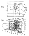
- the nozzle 5 is received on an application head 6, which is fixed by means of an associated holder 7 to a crossbar 8, which is attached to the frame side walls 9 of the folder superstructure or the printing press.
- the application head 6 is required via an attached supply line 10 with the medium to be applied to the assigned paper web and the control signals.
- the nozzle 5 is located in the area of the run-up of the assigned paper web 3 onto the deflection roller 11 arranged above the former 2, which ensures a tight web guidance.
- a constant distance of the web 3 from the associated nozzle 5 is not important, so that the application head 6 could also be further away from the deflecting roller 11 than is the case in the exemplary embodiment shown.
- the position of the application head 6 can be adjusted by correspondingly moving the holder 7 along the crossmember 8. In simple cases, this setting can be made manually.
- a remote-controllable actuating device 12 is provided for this purpose, which can be controlled via a signal line 13 leading to the control panel.
- the number of application heads 6 received on a traverse 8 corresponds to the number of glue lines 4 to be applied to the web 3 in question.
- a central glue line 4 is applied, as already mentioned above, and a centrally arranged application head 6 is accordingly provided.
- a folding aid liquid is applied to the top web of a web package instead of glue in the area of the folding line.
- the same also applies to the underlying webs 3, provided that no glue is to be applied in the area of the fold line.
- glue or folding aid liquid can take place with the help of one and the same application head 6, the depending on the operating mode, glue or folding aid liquid is applied.
- Such an applicator head is therefore, as can best be seen from FIGS.
- control valves 16, 17 are actuated by signal feed lines 18 entering the application head and also contained in the supply line 10.
- the control valve 17 directly upstream of the nozzle 5 can be designed as an interruption valve, with the aid of which interruptions in the liquid line 4 can be generated.
- the other control valve 16 is designed as a multi-way valve, which has an outlet and two inlets, one of which is located on the glue supply line 14 and the other on the folding aid liquid supply line 15. This arrangement not only enables an optional application of glue or folding aid liquid to the nozzle 5 but also enables the nozzle 5 to be flushed with folding aid liquid after the application of glue, for which preferably heated tap water can be used.
- the distributor member 50 can be controlled via a control line 52 so that only the desired application heads 6 are supplied with glue.
- the glue can be pumped out of the glue storage container 51.
- the glue is pressed out of the glue reservoir 51 by pressurizing it.
- the glue surface is pressurized with a compressed air source, here in the form of the internal compressed air network 53, of compressed air which is supplied by means of a pressure line 54.
- the glue reservoir 51 is designed in the illustrated embodiment so that two glue containers can be accommodated, which are alternately emptied. The connection of the pressure line 54 can be switched over accordingly.
- the diameter of the nozzle bore of the nozzle 5 can be in the range of only 0.5 mm. With such a small nozzle opening, the excess network pressure of approximately 1.5 bar is completely sufficient to transport the glue to the nozzle 5 and to spray it off via the nozzle bore.
- the glue pressure is in the low pressure range, so that weak dimensioning of the lines and containers is possible.
- the glue collecting feed line 14a leads via a filter device 55 arranged downstream of the glue storage container 51.
- the filter device 55 also has a compact construction wise no excessive pressure drop.
- the filter of the filter device 55 can be made of stainless steel.
- the 1: 4 size ratio of filter mesh to nozzle bore diameter ensures long-term operation without clogging.
- the dampening liquid supply lines 15 likewise go from a distributor element 56 which can be controlled via a control line 57.
- the distributor member 56 is connected to a corresponding liquid source, in this case in the form of the water supply network 58, via a folding aid liquid collection line 15a.
- the tap water used as a crimping aid liquid is heated above room temperature.
- a continuous flow heater 59 is provided in the collecting feed line 15a.
- additional chemicals are added to the water.
- an admixing device 60 is arranged upstream of the water heater 59.
- the folding aid liquid can be used not only for flushing the nozzles 5, but also for flushing the entire glue application system.
- the glue collecting feed line 14a and the folding aid liquid feed line 15a are connected to one another by a bypass line 61 which branches downstream from the instantaneous heater 59 from the folding aid liquid feed line 15a and in the area of the outlet of the glue storage container 51 into the glue collecting feed line 14a.
- a remotely controllable directional valve 62 is provided, which enables an alternative water flow via the folding aid liquid system or the glue system.
- check valves 63 arranged on both sides are provided at the confluence of the bypass line 61 and the glue collection line 14a.
- rinsing of the application heads 6 is usually sufficient to avoid malfunctions.
- the valve arrangement built into each application head 6 is activated such that the glue supply line is interrupted in the area of all application heads 6 when the web feed is switched off and the folding aid liquid supply line is open.
- the aforementioned rinsing of the application heads 6 or the entire glue application system can be started as soon as the web speed has dropped below approximately one third of the usual web speed, since waste occurs anyway when the printing is finished.
- the control valves 16, 17 can be controlled by means of a computer which processes operating parameters from the general machine control and monitoring.
- the housing of each applicator head 6, as can further be seen in FIG. 3, consists of two shell-shaped halves 27, 28 which can be detachably fixed to one another by plugging them together.
- One half 27 is arranged stationary, ie fixed on the holder 7.
- the supply line 10 leads to the half 27 of the application head 6 fixed on the holder 7, which is provided with a corresponding access bore 20, into which the end of the covering of the supply line 10 can be screwed.
- the wearing parts in the form of the nozzle 5 or the valve arrangement with the control valves 16, 17 are located on the other half 29 of the application head 6, which can be plugged onto the stationary half 27. If it becomes necessary to replace a wearing part, half 28 is simply removed and replaced with a new one.
- the two halves 27, 28 of the application head 6 can be clamped together by means of turnbuckles 30 arranged in the region of mutually opposite sides. These can be designed as toggle levers that can be pivoted beyond their dead center, so that there is an automatic locking.
- one of the two halves can be provided with a circumferential collar 31, which ensures a high level of dust tightness.
- Kende dowel pins 32 may be provided.
- the supply line 10 entering the stationary half 27 contains both the liquid supply lines 14, 15 and the signal supply lines 18. All lines pass over the joint between the two halves 27, 28 of the application head 6. In order nevertheless to enable the loose half 28 to be easily removed, an interruption of these lines, which is bridged by plug-in couplings, is provided in the region of the joint.
- the plug-in couplings assigned to the liquid supply lines 14, 15 are designed as liquid couplings
- the plug-in couplings assigned to the signal supply lines 18 are designed as electrical couplings.
- these plug-in couplings in the exemplary embodiment shown consist of bushes 33 fastened on one half 27 and plug pins 34 fastened on the other half 28, which automatically come into engagement with the respectively assigned socket 33 when the loose half 28 is plugged onto the stationary half 27 .
- the sockets 33 and the plug pins 34 like the dowel pins 32, run parallel to the plugging direction of the attachable halves 28, i.e. perpendicular to the parting plane.
- the coupling elements in the form of the sockets 33 and pins 34 are fastened to support plates 35 and 36 which are parallel to the joint and are inserted in the manner of a cover in the respectively assigned trough-shaped half 27 and 28 of the application head 6.
- the support plates 35 and 36 abut against the interior of the respectively associated half 27 and 28 of the application head 6 and are screwed to it.
- the pins 34 of the fluid couplings are in the The illustrated embodiment is designed as a hollow pin which engages with play in the respectively assigned socket 33.
- the radial distance is bridged by an O-ring 37.
- a check valve 38 is arranged upstream of the sockets 33 of the fluid couplings received on the stationary half 27, the closing element of which is held in the open position by the pin 34 engaging in the socket 33 in question.
- the plug pins 34 of the fluid couplings are provided with a plunger 39 which engages in the upstream check valve 38 in the engagement position.
- the hollow pins in question are provided with a radial input bore. The plungers 39 ensure that the liquid feed lines 14 and 15 are automatically closed when the loose half 28 is pulled off, so that no liquid can be spilled.
- the sockets 33 of the fluid couplings are designed as nipples screwed into the assigned through bores of the support plate 35, to which the respective upstream check valve 38 is attached.
- the plug pins 34 of the fluid couplings are also provided with threaded nipples which are screwed here into an associated blind hole in the support plate 36. From each of the blind bores mentioned, a tap hole extends into which a connecting nipple 40 is screwed, which is connected to the control valve 16 via a front section of the liquid supply line 14 or 15, as indicated in FIG. 2 by dash-dotted lines.
- the sockets 33 of the electrical couplings assigned to the signal lines 18 are inserted into a carrier 41 made of insulating material and wired to the assigned signal lines, as indicated by the terminals 42.
- the electrical couplings are arranged centrally between the fluid couplings, so that the sockets 33 or plug pins 34 assigned to each of the signal lines 18 can each be received on a common, insulating carrier 41.
- the control valves 16 and 17, which are wired to the plug pins of the electrical couplings, can be fastened in the area between the connecting nipples 40 on the rear side of the associated support plate 36.
Priority Applications (1)
| Application Number | Priority Date | Filing Date | Title |
|---|---|---|---|
| EP91106388A EP0446963B1 (fr) | 1987-10-23 | 1988-10-18 | Dispositif pour déposer une bande de liquide sur au moins une bande de matériau en mouvement |
Applications Claiming Priority (4)
| Application Number | Priority Date | Filing Date | Title |
|---|---|---|---|
| DE3735856 | 1987-10-23 | ||
| DE3735856 | 1987-10-23 | ||
| DE3740045 | 1987-11-26 | ||
| DE19873740045 DE3740045A1 (de) | 1987-10-23 | 1987-11-26 | Verfahren und vorrichtung zum auftragen wenigstens eines leimstreifens auf mindestens eine materialbahn |
Related Child Applications (1)
| Application Number | Title | Priority Date | Filing Date |
|---|---|---|---|
| EP91106388.1 Division-Into | 1991-04-20 |
Publications (3)
| Publication Number | Publication Date |
|---|---|
| EP0312974A2 true EP0312974A2 (fr) | 1989-04-26 |
| EP0312974A3 EP0312974A3 (en) | 1990-10-03 |
| EP0312974B1 EP0312974B1 (fr) | 1994-03-30 |
Family
ID=25861029
Family Applications (2)
| Application Number | Title | Priority Date | Filing Date |
|---|---|---|---|
| EP91106388A Expired - Lifetime EP0446963B1 (fr) | 1987-10-23 | 1988-10-18 | Dispositif pour déposer une bande de liquide sur au moins une bande de matériau en mouvement |
| EP88117289A Expired - Lifetime EP0312974B1 (fr) | 1987-10-23 | 1988-10-18 | Procédé de jonction de deux bandes de matériau |
Family Applications Before (1)
| Application Number | Title | Priority Date | Filing Date |
|---|---|---|---|
| EP91106388A Expired - Lifetime EP0446963B1 (fr) | 1987-10-23 | 1988-10-18 | Dispositif pour déposer une bande de liquide sur au moins une bande de matériau en mouvement |
Country Status (5)
| Country | Link |
|---|---|
| US (2) | US4952267A (fr) |
| EP (2) | EP0446963B1 (fr) |
| JP (1) | JPH0649165B2 (fr) |
| DE (3) | DE3740045A1 (fr) |
| ES (2) | ES2053673T3 (fr) |
Cited By (3)
| Publication number | Priority date | Publication date | Assignee | Title |
|---|---|---|---|---|
| EP0410400A2 (fr) * | 1989-07-28 | 1991-01-30 | PLANATOL - Klebetechnik Gesellschaft mit beschränkter Haftung | Dispositif pour l'alimentation en matériau de plieuses et dispositifs de mouillage dans des machines à imprimer |
| CN103538388A (zh) * | 2012-07-10 | 2014-01-29 | 海德堡印刷机械股份公司 | 用于涂覆粘接材料的装置以及用于运行这种装置的方法 |
| CN110626006A (zh) * | 2019-09-29 | 2019-12-31 | 佛山市豹王海莎过滤器有限公司 | 滤清器滤芯贴边机 |
Families Citing this family (11)
| Publication number | Priority date | Publication date | Assignee | Title |
|---|---|---|---|---|
| DE4122105C2 (de) * | 1991-07-04 | 1995-02-02 | Kotterer Grafotec | Vorrichtung zum berührungslosen Auftragen eines Flüssigkeitsstreifens auf eine laufende Materialbahn |
| DE9110790U1 (fr) * | 1991-08-31 | 1992-09-24 | Planatolwerk Willy Hesselmann Chemische Und Maschinenfabrik Fuer Klebetechnik Gmbh & Co Kg, 8201 Rohrdorf, De | |
| DE4341566B4 (de) * | 1993-12-07 | 2005-03-10 | Heidelberger Druckmasch Ag | Trennmittelschichten zum Oberflächenschutz frisch bedruckter Bogen und Vorrichtung zum Beschichten der frisch bedruckten Bogen mit der Trennmittelschicht |
| DE4416311A1 (de) * | 1994-05-09 | 1995-11-16 | Itw Oberflaechentechnik Gmbh | Sprühgerät-Befestigungsvorrichtung |
| DK0765220T3 (da) * | 1994-06-24 | 2002-04-22 | Pactiv Corp | Maskine til fremstilling af honeycomb-materiale |
| DE4422724A1 (de) | 1994-06-29 | 1996-01-11 | Kotterer Grafotec | Verfahren und Vorrichtung zum Verbinden von mindestens zwei Lagen eines mehrlagigen Bahnstranges |
| DE19504652C2 (de) * | 1995-02-13 | 1999-06-24 | Grafotec Gmbh | Vorrichtung zur Erzeugung eines strichförmigen Auftrags von Leim oder Softflüssigkeit |
| US5873702A (en) * | 1997-06-20 | 1999-02-23 | Siemens Westinghouse Power Corporation | Apparatus and method for sealing gas turbine blade roots |
| DE10119520A1 (de) * | 2001-04-20 | 2002-10-24 | Duerr Systems Gmbh | Verfahren und Ventilanordnung für die Flüssigkeitsversorgung eines abkuppelbaren Teils einer Beschichtungsanlage |
| DE10231598A1 (de) | 2001-08-07 | 2003-02-20 | Heidelberger Druckmasch Ag | Vorrichtung zum Wiederbefeuchten einer Warenbahn |
| DE102008027994B3 (de) * | 2008-06-12 | 2010-04-01 | Dürr Systems GmbH | Applikator zur Applikation eines Dichtungsmittels auf eine Bördelnaht |
Citations (4)
| Publication number | Priority date | Publication date | Assignee | Title |
|---|---|---|---|---|
| US2198460A (en) * | 1938-11-29 | 1940-04-23 | Fay E Rickard | Method and apparatus for folding paper and the like |
| US2747865A (en) * | 1951-06-02 | 1956-05-29 | Jr Joseph R Marshall | Booklet forming means and method |
| DE3215372A1 (de) * | 1982-04-24 | 1983-11-03 | Böger-Kommerz KG, 6204 Taunusstein | Pneumatisch und/oder hydraulische steckverbindung |
| GB2165470A (en) * | 1984-10-15 | 1986-04-16 | Amco Corp | Spray head |
Family Cites Families (22)
| Publication number | Priority date | Publication date | Assignee | Title |
|---|---|---|---|---|
| US2510125A (en) * | 1946-07-30 | 1950-06-06 | Lawrence W Meakin | Connector for fluid or electrical lines or both |
| FR1022842A (fr) * | 1950-03-09 | 1953-03-10 | Goss Printing Press Co Ltd | Dispositif d'encollage de feuilles |
| US2847196A (en) * | 1955-06-28 | 1958-08-12 | Philip J Franklin | Dispenser for thermosetting materials |
| US3134706A (en) * | 1961-07-31 | 1964-05-26 | Robert C Alexander | Apparatus for securing the free terminal end of a roll of rolled paper |
| US3179341A (en) * | 1962-06-19 | 1965-04-20 | Binks Mfg Co | Spray gun |
| US3530774A (en) * | 1967-12-13 | 1970-09-29 | Hoerner Waldorf Corp | Method of making a flat bottom multi-ply bag |
| US3590775A (en) * | 1968-02-26 | 1971-07-06 | Stuart W Barr | Glue spray system |
| US3808088A (en) * | 1969-12-29 | 1974-04-30 | Goodrich Co B F | Spot bonded laminates |
| US3661679A (en) * | 1970-09-08 | 1972-05-09 | Lockwood Tech | Adhesive applicator for plywood patching machine |
| DE2058667B1 (de) * | 1970-11-28 | 1972-05-25 | Weitmann & Konrad | Vorrichtung in Druckereimaschinen,insbesondere Offsetmaschinen,zum Aufbringen von Fluessigkeit auf bewegte Flaechen |
| US3821055A (en) * | 1971-12-23 | 1974-06-28 | Minnesota Mining & Mfg | Fabric pattern construction method |
| JPS5314379Y2 (fr) * | 1973-12-01 | 1978-04-17 | ||
| JPS50156569U (fr) * | 1974-06-15 | 1975-12-25 | ||
| US4141544A (en) * | 1974-07-26 | 1979-02-27 | Maschinenfabrik Augsburg-Nurnberg Aktiengesellschaft | Apparatus for longitudinal deformation, for example by creasing or perforation, of paper webs prior to folding |
| JPS5527880A (en) * | 1978-08-21 | 1980-02-28 | Tanto Kk | Glazing device |
| US4313899A (en) * | 1980-02-07 | 1982-02-02 | Champion International Corporation | Process for forming laminated paperboard containers |
| US4427153A (en) * | 1982-08-16 | 1984-01-24 | Graco Inc. | Plural component dispensing device |
| JPS6086185A (ja) * | 1983-10-19 | 1985-05-15 | Aica Kogyo Co Ltd | 吹付施工用接着剤 |
| US4572438A (en) * | 1984-05-14 | 1986-02-25 | Nordson Corporation | Airless spray gun having improved nozzle assembly and electrode circuit connections |
| US4917300A (en) * | 1985-04-25 | 1990-04-17 | Stewart Warner Alemite Corporation | Paint spray gun |
| DE3540588A1 (de) * | 1985-11-15 | 1987-05-21 | Hoechst Ag | Entschichtungsvorrichtung |
| JPS62236814A (ja) * | 1986-04-08 | 1987-10-16 | Denki Kagaku Kogyo Kk | 光硬化性樹脂組成物 |
-
1987
- 1987-11-26 DE DE19873740045 patent/DE3740045A1/de active Granted
-
1988
- 1988-09-21 US US07/247,341 patent/US4952267A/en not_active Expired - Lifetime
- 1988-10-18 DE DE3851158T patent/DE3851158D1/de not_active Expired - Lifetime
- 1988-10-18 ES ES88117289T patent/ES2053673T3/es not_active Expired - Lifetime
- 1988-10-18 DE DE88117289T patent/DE3888782D1/de not_active Expired - Fee Related
- 1988-10-18 EP EP91106388A patent/EP0446963B1/fr not_active Expired - Lifetime
- 1988-10-18 EP EP88117289A patent/EP0312974B1/fr not_active Expired - Lifetime
- 1988-10-18 ES ES91106388T patent/ES2062602T3/es not_active Expired - Lifetime
- 1988-10-20 JP JP63265205A patent/JPH0649165B2/ja not_active Expired - Fee Related
-
1990
- 1990-04-16 US US07/509,235 patent/US5062919A/en not_active Expired - Lifetime
Patent Citations (4)
| Publication number | Priority date | Publication date | Assignee | Title |
|---|---|---|---|---|
| US2198460A (en) * | 1938-11-29 | 1940-04-23 | Fay E Rickard | Method and apparatus for folding paper and the like |
| US2747865A (en) * | 1951-06-02 | 1956-05-29 | Jr Joseph R Marshall | Booklet forming means and method |
| DE3215372A1 (de) * | 1982-04-24 | 1983-11-03 | Böger-Kommerz KG, 6204 Taunusstein | Pneumatisch und/oder hydraulische steckverbindung |
| GB2165470A (en) * | 1984-10-15 | 1986-04-16 | Amco Corp | Spray head |
Non-Patent Citations (2)
| Title |
|---|
| I. SKEIST: "HANDBOOK OF ADHESIVES" 1977, VAN NOSTRAND REINHOLD CO., NEW YORK , KAPITEL 32 "ACRYLIC ADHESIVES AND SEALANTS" * |
| J. SHIELDS: "ADHESIVES HANDBOOK" 1970, BUTTERWORTH, LONDON * |
Cited By (5)
| Publication number | Priority date | Publication date | Assignee | Title |
|---|---|---|---|---|
| EP0410400A2 (fr) * | 1989-07-28 | 1991-01-30 | PLANATOL - Klebetechnik Gesellschaft mit beschränkter Haftung | Dispositif pour l'alimentation en matériau de plieuses et dispositifs de mouillage dans des machines à imprimer |
| EP0410400A3 (en) * | 1989-07-28 | 1991-05-08 | Planatolwerk Willy Hesselmann Chemische Und Maschinenfabrik Fuer Klebetechnik Gmbh & Co. Kg | Device for feeding material to folding and damping devices of rotary printing machines |
| CN103538388A (zh) * | 2012-07-10 | 2014-01-29 | 海德堡印刷机械股份公司 | 用于涂覆粘接材料的装置以及用于运行这种装置的方法 |
| CN110626006A (zh) * | 2019-09-29 | 2019-12-31 | 佛山市豹王海莎过滤器有限公司 | 滤清器滤芯贴边机 |
| CN110626006B (zh) * | 2019-09-29 | 2020-12-08 | 佛山市豹王海莎过滤器有限公司 | 滤清器滤芯贴边机 |
Also Published As
| Publication number | Publication date |
|---|---|
| DE3740045C2 (fr) | 1989-07-27 |
| DE3851158D1 (de) | 1994-09-22 |
| ES2062602T3 (es) | 1994-12-16 |
| DE3740045A1 (de) | 1989-05-03 |
| JPH01143661A (ja) | 1989-06-06 |
| US4952267A (en) | 1990-08-28 |
| EP0312974A3 (en) | 1990-10-03 |
| JPH0649165B2 (ja) | 1994-06-29 |
| DE3888782D1 (de) | 1994-05-05 |
| EP0312974B1 (fr) | 1994-03-30 |
| EP0446963A1 (fr) | 1991-09-18 |
| EP0446963B1 (fr) | 1994-08-17 |
| ES2053673T3 (es) | 1994-08-01 |
| US5062919A (en) | 1991-11-05 |
Similar Documents
| Publication | Publication Date | Title |
|---|---|---|
| EP0312974B1 (fr) | Procédé de jonction de deux bandes de matériau | |
| AT393246B (de) | Auftragsvorrichtung zum aufbringen fliessfaehiger medien auf ebene flaechen, bahnen, walzen od. dgl. | |
| EP0313039B1 (fr) | Procédé et dispositif de pliage d'une bande de papier | |
| DE2640828B2 (de) | Vorrichtung zum Auftragen von Klebstoff | |
| EP0063244B1 (fr) | Dispositif d'application d'adhésifs | |
| DE3200469C2 (de) | Einrichtung zum längenabschnittweisen Auftragen von Leim auf eine laufende Bahn | |
| EP2392408A1 (fr) | Dispositif d'application de colle et procédé de nettoyage de celui-ci | |
| EP0570727A1 (fr) | Dispositif de lavage pour machines à imprimer | |
| DE60004659T2 (de) | Vorrichtung für das dosieren und die verteilung von hotmelt | |
| EP0570763B1 (fr) | Dispositif de lavage pour machine à imprimer | |
| DE3120260C2 (fr) | ||
| DE2724888B2 (de) | Vorrichtung zur Reinigung von Tuscheschreiberspitzen | |
| DE3200470A1 (de) | Einrichtung zum auftragen von leim | |
| EP1050343B1 (fr) | Dispositif de pulvérisation, en particulier pour une machine d'impression | |
| DE4224975C2 (de) | Vorrichtung zum Auftragen von Klebstoffen auf bewegte Bahnen oder Werkstücke | |
| DE102019006362A1 (de) | Vorrichtung zum Zuführen eines Mediums zu einem Werkzeug einer Bearbeitungsmaschine und Verfahren zum Bereitstellen einer derartigen Vorrichtung | |
| DE102020117617A1 (de) | Ventilanordnung | |
| EP2091737B1 (fr) | Procédé de nettoyage ainsi que dispositif de nettoyage pour une surface cylindrique d'une machine d'impression | |
| DE10322320B4 (de) | Ventilanordnung für Sprühfeuchtwerke von Druckmaschinen | |
| EP0627268A2 (fr) | Dispositif de pulvérisation de liquide, en particulier pour les machines à imprimer | |
| EP0582060B1 (fr) | Dispositif pour l'application de matières visqueuses | |
| WO2004071769A1 (fr) | Machine a imprimer equipee d'une unite de soufflage d'air servant a secher un support d'impression | |
| EP1391554A2 (fr) | Dispositif d'enduction | |
| EP1642717B1 (fr) | Dispositif de nettoyage de surfaces de cylindres dans une machine d'impression | |
| DE3532933C2 (fr) |
Legal Events
| Date | Code | Title | Description |
|---|---|---|---|
| PUAI | Public reference made under article 153(3) epc to a published international application that has entered the european phase |
Free format text: ORIGINAL CODE: 0009012 |
|
| AK | Designated contracting states |
Kind code of ref document: A2 Designated state(s): CH DE ES FR GB IT LI SE |
|
| PUAL | Search report despatched |
Free format text: ORIGINAL CODE: 0009013 |
|
| AK | Designated contracting states |
Kind code of ref document: A3 Designated state(s): CH DE ES FR GB IT LI SE |
|
| 17P | Request for examination filed |
Effective date: 19901219 |
|
| 17Q | First examination report despatched |
Effective date: 19920708 |
|
| GRAA | (expected) grant |
Free format text: ORIGINAL CODE: 0009210 |
|
| AK | Designated contracting states |
Kind code of ref document: B1 Designated state(s): CH DE ES FR GB IT LI SE |
|
| XX | Miscellaneous (additional remarks) |
Free format text: TEILANMELDUNG 91106388.1 EINGEREICHT AM 18/10/88. |
|
| REF | Corresponds to: |
Ref document number: 3888782 Country of ref document: DE Date of ref document: 19940505 |
|
| ITF | It: translation for a ep patent filed |
Owner name: ING. C. SPANDONARI |
|
| GBT | Gb: translation of ep patent filed (gb section 77(6)(a)/1977) |
Effective date: 19940518 |
|
| REG | Reference to a national code |
Ref country code: ES Ref legal event code: FG2A Ref document number: 2053673 Country of ref document: ES Kind code of ref document: T3 |
|
| ET | Fr: translation filed | ||
| PLBI | Opposition filed |
Free format text: ORIGINAL CODE: 0009260 |
|
| EAL | Se: european patent in force in sweden |
Ref document number: 88117289.4 |
|
| 26 | Opposition filed |
Opponent name: FALCO-SIEBRASSE GMBH Effective date: 19941228 Opponent name: PLANATOL KLEBETECHNIK GMBH Effective date: 19941223 |
|
| RAP2 | Party data changed (patent owner data changed or rights of a patent transferred) |
Owner name: GRAFOTEC GMBH |
|
| PGFP | Annual fee paid to national office [announced via postgrant information from national office to epo] |
Ref country code: CH Payment date: 19970915 Year of fee payment: 10 |
|
| PGFP | Annual fee paid to national office [announced via postgrant information from national office to epo] |
Ref country code: ES Payment date: 19971006 Year of fee payment: 10 |
|
| PG25 | Lapsed in a contracting state [announced via postgrant information from national office to epo] |
Ref country code: ES Free format text: LAPSE BECAUSE OF EXPIRATION OF PROTECTION Effective date: 19981019 |
|
| PG25 | Lapsed in a contracting state [announced via postgrant information from national office to epo] |
Ref country code: LI Free format text: LAPSE BECAUSE OF NON-PAYMENT OF DUE FEES Effective date: 19981031 Ref country code: CH Free format text: LAPSE BECAUSE OF NON-PAYMENT OF DUE FEES Effective date: 19981031 |
|
| REG | Reference to a national code |
Ref country code: CH Ref legal event code: PL |
|
| PLBO | Opposition rejected |
Free format text: ORIGINAL CODE: EPIDOS REJO |
|
| PLBN | Opposition rejected |
Free format text: ORIGINAL CODE: 0009273 |
|
| STAA | Information on the status of an ep patent application or granted ep patent |
Free format text: STATUS: OPPOSITION REJECTED |
|
| 27O | Opposition rejected |
Effective date: 19990608 |
|
| REG | Reference to a national code |
Ref country code: ES Ref legal event code: FD2A Effective date: 20010201 |
|
| REG | Reference to a national code |
Ref country code: GB Ref legal event code: IF02 |
|
| PGFP | Annual fee paid to national office [announced via postgrant information from national office to epo] |
Ref country code: GB Payment date: 20020827 Year of fee payment: 15 |
|
| PGFP | Annual fee paid to national office [announced via postgrant information from national office to epo] |
Ref country code: FR Payment date: 20020828 Year of fee payment: 15 |
|
| PGFP | Annual fee paid to national office [announced via postgrant information from national office to epo] |
Ref country code: SE Payment date: 20021024 Year of fee payment: 15 |
|
| PG25 | Lapsed in a contracting state [announced via postgrant information from national office to epo] |
Ref country code: GB Free format text: LAPSE BECAUSE OF NON-PAYMENT OF DUE FEES Effective date: 20031018 |
|
| PG25 | Lapsed in a contracting state [announced via postgrant information from national office to epo] |
Ref country code: SE Free format text: LAPSE BECAUSE OF NON-PAYMENT OF DUE FEES Effective date: 20031019 |
|
| EUG | Se: european patent has lapsed | ||
| GBPC | Gb: european patent ceased through non-payment of renewal fee |
Effective date: 20031018 |
|
| PG25 | Lapsed in a contracting state [announced via postgrant information from national office to epo] |
Ref country code: FR Free format text: LAPSE BECAUSE OF NON-PAYMENT OF DUE FEES Effective date: 20040630 |
|
| REG | Reference to a national code |
Ref country code: FR Ref legal event code: ST |
|
| PG25 | Lapsed in a contracting state [announced via postgrant information from national office to epo] |
Ref country code: IT Free format text: LAPSE BECAUSE OF NON-PAYMENT OF DUE FEES;WARNING: LAPSES OF ITALIAN PATENTS WITH EFFECTIVE DATE BEFORE 2007 MAY HAVE OCCURRED AT ANY TIME BEFORE 2007. THE CORRECT EFFECTIVE DATE MAY BE DIFFERENT FROM THE ONE RECORDED. Effective date: 20051018 |
|
| PGFP | Annual fee paid to national office [announced via postgrant information from national office to epo] |
Ref country code: DE Payment date: 20060908 Year of fee payment: 19 |
|
| PG25 | Lapsed in a contracting state [announced via postgrant information from national office to epo] |
Ref country code: DE Free format text: LAPSE BECAUSE OF NON-PAYMENT OF DUE FEES Effective date: 20080501 |