EP0312049B1 - Spritzgiessvorrichtung zum Herstellen von Kunststoffgegenständen - Google Patents
Spritzgiessvorrichtung zum Herstellen von Kunststoffgegenständen Download PDFInfo
- Publication number
- EP0312049B1 EP0312049B1 EP88117019A EP88117019A EP0312049B1 EP 0312049 B1 EP0312049 B1 EP 0312049B1 EP 88117019 A EP88117019 A EP 88117019A EP 88117019 A EP88117019 A EP 88117019A EP 0312049 B1 EP0312049 B1 EP 0312049B1
- Authority
- EP
- European Patent Office
- Prior art keywords
- sheet
- mold
- magnet
- resin
- fitted
- Prior art date
- Legal status (The legal status is an assumption and is not a legal conclusion. Google has not performed a legal analysis and makes no representation as to the accuracy of the status listed.)
- Expired - Lifetime
Links
Images

Classifications
-
- B—PERFORMING OPERATIONS; TRANSPORTING
- B29—WORKING OF PLASTICS; WORKING OF SUBSTANCES IN A PLASTIC STATE IN GENERAL
- B29C—SHAPING OR JOINING OF PLASTICS; SHAPING OF MATERIAL IN A PLASTIC STATE, NOT OTHERWISE PROVIDED FOR; AFTER-TREATMENT OF THE SHAPED PRODUCTS, e.g. REPAIRING
- B29C45/00—Injection moulding, i.e. forcing the required volume of moulding material through a nozzle into a closed mould; Apparatus therefor
- B29C45/14—Injection moulding, i.e. forcing the required volume of moulding material through a nozzle into a closed mould; Apparatus therefor incorporating preformed parts or layers, e.g. injection moulding around inserts or for coating articles
- B29C45/14065—Positioning or centering articles in the mould
-
- B—PERFORMING OPERATIONS; TRANSPORTING
- B29—WORKING OF PLASTICS; WORKING OF SUBSTANCES IN A PLASTIC STATE IN GENERAL
- B29C—SHAPING OR JOINING OF PLASTICS; SHAPING OF MATERIAL IN A PLASTIC STATE, NOT OTHERWISE PROVIDED FOR; AFTER-TREATMENT OF THE SHAPED PRODUCTS, e.g. REPAIRING
- B29C33/00—Moulds or cores; Details thereof or accessories therefor
- B29C33/12—Moulds or cores; Details thereof or accessories therefor with incorporated means for positioning inserts, e.g. labels
- B29C33/14—Moulds or cores; Details thereof or accessories therefor with incorporated means for positioning inserts, e.g. labels against the mould wall
- B29C33/16—Moulds or cores; Details thereof or accessories therefor with incorporated means for positioning inserts, e.g. labels against the mould wall using magnetic means
-
- Y—GENERAL TAGGING OF NEW TECHNOLOGICAL DEVELOPMENTS; GENERAL TAGGING OF CROSS-SECTIONAL TECHNOLOGIES SPANNING OVER SEVERAL SECTIONS OF THE IPC; TECHNICAL SUBJECTS COVERED BY FORMER USPC CROSS-REFERENCE ART COLLECTIONS [XRACs] AND DIGESTS
- Y10—TECHNICAL SUBJECTS COVERED BY FORMER USPC
- Y10S—TECHNICAL SUBJECTS COVERED BY FORMER USPC CROSS-REFERENCE ART COLLECTIONS [XRACs] AND DIGESTS
- Y10S425/00—Plastic article or earthenware shaping or treating: apparatus
- Y10S425/033—Magnet
Definitions
- This invention relates to a mold apparatus for producing a synthetic resin article composed of a film or sheet and an injected resin part, comprising a mold including a cavity and a resin passageway at a gate to the cavity, and a magnet buried in the mold to form a magnet fixing part for fixing the film or sheet having a ferromagnetic substance fitted thereto at a position or positions corresponding to said magnet fixing part of the mold.
- the film or sheet has a function to impart surface gloss, hardness, ultraviolet light resistance, infrared absorption properties or other characteristics or having letters, marks or other designs.
- vacuum method when the fitting method by vaccum suction (hereinafter referred to as vacuum method) is applied to production of large-sized articles or articles having a curved surface, a gap may be formed between the sheet and the mold due to the shock or vibration on mold closing to reduce the sucking force. If a resin is injected under such a state, the sheet is shifted out of its proper position or suffers wrinkling, or the sheet is expanded or contracted due to the heat of the injected resin to cause wrinkling. When the article has a curved surface, it is difficult to fit the sheet, particularly its end portions, intimate to the mold because of its rigidity. Even if the sheet is once fitted, the same problem as stated above is apt to arise. Further, since the vacuum method essentially requires a mold having special vacuum ports for suction on the inner wall and vacuum-lines in the inside, the mold is expensive and the operation is complicated.
- JP-A-62 62 719 it is known to provide a plurality of magnet pieces in the surface of a mold constituting a cavity.
- the plurality of magnetic pieces hold reinforcing material having metallic substances placed on the top surface thereof.
- This apparatus it is possible to obtain a resin molded article including reinforcing material.
- This apparatus is, however, not suited for fixing a film or sheet precisely on the surface of the molded article, and does not ensure that the position of the film does not change even if the pressure of the reinjected resin is high.
- the mold apparatus according to the present invention enables the sheet or film to be automatically fitted to a prescribed position of the mold. With this apparatus, molded resin articles can be obtained which are excellent in not only two-dimensional but three-dimensional appearance even if the article is of large size.
- Figure 1 is a plane view of an example of a transparent molded article according to the present invention.
- Figure 2 is a sectional view of a gate and its vicinities of a mold for producing the article of Fig. 1.
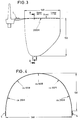
- Figure 3 is a plane view of a curved molded article prepared according to Example 2 of the present invention.
- Figure 4 is a cross-sectional end view taken on line A-A of Fig. 3.
- a molded article comprises main body 1 and gate 2.
- gate 2 has a fan shape expanding toward main body 1, which is suitable for producing a large-sized transparent molded article.
- Gate 2 is composed of resin introduction part 6 directly connected to runner 5, fixing part 7 for fixing with a magnet, and fan-shaped part 8.
- the fixing part 7, which is provided by the both sides of the resin passageway, has a form of wings for preventing the sheet from shifting, and iron sheet 4 is fitted to the fixing part 7 so that the sheet may be fitted and fixed to the inner wall of the mold by magnetic force.
- fixing parts 7′ can be provided at the position opposite to the gate and also at the both sides of the sheet. In this particular case of Fig.
- the fixing parts 7′ are not always needed. However, in order to prevent the sheet from fluttering or being caught between molds or the like troubles due to vibration or shock on mold closing, the fixing part 7′ is preferably provided at the position opposite to the gate. When the molded article has a curved surface or a large size, it is preferable that such a fixing part be provided at not only all of the positions shown but also other appropriate positions not shown.
- Fig. 2 illustrates a section of gate 2 and its vicinities of the mold for producing the molded article shown in Fig. 1.
- Mold 20 has gate 22 directly connected to runner 25 and cavity 21 corresponding to the main body of the molded article.
- recesses are formed by engraving from the cavity side, into which magnet 29, the side surface thereof being coated with brass, is buried to form magnetic fixing part 27.
- the portion of the mold cavity where the fixing part 27 is formed has a larger thickness than the main body, that is, the portion of the cavity has a deeper impression than the portion of the main body as shown in Fig. 2.
- the fixing part 27 is preferably provided in the both sides (wings) of the resin passageway but not right above or under the resin passageway so that the magnet or ferromagnetic substance (e.g., a piece of iron sheet) fitted to the sheet may not move to the main body side together with the resin flow to cause damage of the mold or the sheet may not shift in the direction of the resin flow.
- the magnet or ferromagnetic substance e.g., a piece of iron sheet
- the above-described troubles such as mold damage with the magnet or ferromagnetic substance
- the mold is provided with an anti-sheet-shift part, such as pins (e.g., rod-like pin, top edge-round pin, etc.), vacuum ports and the like, in order to prevent the sheet from moving toward the resin flow direction. Movement of the sheet toward the resin flow direction can also be prevented by interposing the sheet between two molds.
- the interposition part of the mold on which the sheet is fitted has a depression in a depth smaller than the thickness of the sheet.
- the above-described special designing is not required for the magnet fixing parts 7′ shown or not shown in Fig. 1 because they are in the downstream side with respect to the resin introduction part and, in addition, they are expected to serve to absorb expansion and contraction of the sheet due to the injected resin to thereby prevent wrinkling of the sheet.
- the magnet to be buried in the mold may be selected from permanent magnet and electromagnet in accordance with the shape of the molded article, the cost of the mold, and the like. In view of ease in production of the mold, permanent magnet would be suitable.
- Permanent magnet includes alloy magnet, e.g., alunico, Fe-Cr-Co magnet, Cu-Ni-Fe magnet, Mn-Al magnet; oxide (ferrite) magnet; rare earth metal-cobalt magnet; and bond magnet comprising these materials bonded with resins, etc..
- the magnetic core material of the electromagnet includes pure iron, Fe-Ni alloys, silicon steel, Fe-Al alloys, Fe-Co alloys, ferrite, etc.
- the aforesaid magnet can be buried in the recess of the mold by fixing with a heat-resistant thermosetting resin, or inserting the magnet whose pheriphery is covered with a soft material, e.g., copper or copper alloys.
- the attracting force between the sheet and the mold per magnet fixing part can be controlled to some extent by adjusting the magnetic force of the magnet fitted to the mold or the thickness or size of the magnet or ferromagnetic substance fitted to the sheet.
- an attracting force (or pull strength) in the vertical direction of about 0.5 kg would be enough to obtain firm fit comparable to that obtained by vacuum fitting.
- Th positions and attracting force of the magnet fixing parts other than that provided in the vicinities of a gate are selected appropriately depending on the shape of the desired molded article (inclusive of whether the article has a plane surface or a curved surface) and the size and thickness of the sheet.
- a plurality of magnet fixing parts should be provided so that the sheet may be well fitted along the curved surface of the mold cavity. The attracting force of these fixing parts can be determined taking the thickness of the sheet to be fitted and the curvature of the mold into consideration.
- the attracting force of the fixing parts in positions where the sheet exercises its stiffness should be made greater by increasing the strength of the magnet or the thickness or size of the ferromagnetic substance to be fitted to the sheet.
- both the magnets in the cavity side facing each other with the cavity therebetween) have the same magnetic pole.
- the sheet (or film) which can be used in the present invention is a film usually having a thickness of from 0.2 to 1 mm and functioning to impart various performances, such as surface gloss, scratch resistance, ultraviolet light resistance, infrared absorption properties, anti-fogging properties, anti-reflection properties, and the like.
- the sheet may have appropriately formed thereon letters, marks or other designs. It is generally produced from polycarbonate resins, polysulfone resins, acrylic resins, and other transparent thermoplastic resins, with a polycarbonate sheet being preferred. In order to ensure adhesion to injected thermoplastic resins, a back coat may be formed on the back side of the sheet.
- a polycarbonate sheet having a back coat of an acrylic resin is used in the case of injecting an acrylic resin, an ABS resin, an AS resin, a polystyrene resin, etc.; a polycarbonate sheet having a back coat of a non-crystalline saturated polyester resin which is used as a hot melt adhesive is used in the case of injecting an aromatic saturated polyester resin, e.g., PET and PBT; or a polycarbonate sheet having a back coat of an EVA resin is used for general use where heat resistance is not particularly required.
- the magnet or ferromagnetic substance to be fitted to the sheet includes a plastic magnet sheet comprising the above-described permanent magnet and a plastic, an iron sheet, a cobalt sheet, a nickel sheet, etc.
- a plastic magnet sheet comprising the above-described permanent magnet and a plastic
- an iron sheet e.g., a zinc-plated iron sheet
- These magnet or ferromagnetic sheet have a thickness of from about 0.05 to about 0.5 mm. If the thickness is too small, the attracting force would be insufficient unless a strong magnet should be used, or the magnet should be exchanged, or the preset voltage should be increased in the case of using an electromagnet.
- a magnet or a ferromagnetic substance having a thickness exceeding about 0.5 mm is fitted on the side in contact with the mold, a recess having a depth approximate to the thickness of the sheet fitted with such a thick magnet or ferromagnetic substance should be formed on the inner wall of the mold. Otherwise, a large gap would be formed between the sheet and the mold wall.
- the magnetic pole thereof should be opposite to that of the magnet fixing part.
- Fitting of the magnet or ferromagnetic substance to the sheet can be carried out, for example, by using a magnet or ferromagnetic piece having nibs or clicks to bite the sheet, or by heat fusion, or by adhesion with an adhesive or a self-adhesive.
- the magnet or ferromagnetic substance is preferably fitted to the sheet on the side to be contacted with the mold so as to attain an ensured attracting force and to reduce the resistance to the flowing resin.
- thermoplastic resin to be injection molded is not particularly limited and includes transparent to opaque resins or may contain fillers. From the standpoint of taking full advantage of the present invention, transparent thermoplastic resins are preferred.
- a mold for producing an article of Fig. 1 (a flat plate of 300 x 300 x 4 mm) was used.
- Each of the movable mold and the fixed mold had buried therein a permanent magnet having a diameter of 10 mm and a length of 15 mm in two points at the gate (i.e., in each of wings at the gate) and one point opposite to the gate in such a manner that each pair of the magnet facing each other have opposite poles.
- Two blanks having a shape of Fig. 1 were prepared from an aromatic polycarbonate sheet having a hard coat on one side thereof.
- a steel sheet having a diameter of 12 mm and a thickness of 0.1 mm was fixed to each of the blanks on its hard coat side by means of an adhesive tape at three positions corresponding to the magnet-fixed parts of the mold to prepare two sheets fitted with pieces of steel sheet.
- the sheet with steel pieces was fitted to each of the movable and fixed molds in such a manner that the hard coat side contacted the mold wall.
- the sheet could be fitted to the mold at the prescribed position simply by bringing it close to the position.
- the pulling strength required for separating the sheet from the mold at the magnet fixing part in the vertical direction was about 0.3 kg per magnet fixing part.
- the resulting molded article was found to have satisfactory appearance without suffering shift or wrinkling of the sheet in the vicinities of the gate or infiltration of the injected resin between the sheet and the mold.
- the pulling strength per magnet fixing part was about 0.6 kg.
- a helmet cover (protective glass) was produced as a curved molded article.
- the mold used had a gate portion having the same shape as shown in Fig. 1 at a front, central and upper edge portion of the helmet cover, and had a shape that height of a center portion is 140 mm, its curvature radius is 2,000 mm, width is 260 mm, depth is 150 mm, curvature radius of the front portion is about 160 mm, the curvature radius of the side portion is about 200 cm, the curvature radius of from the front portion to the side portion is about 100 cm, and thickness is 2.2 mm as shown in Figs. 3 and 4.
- Wings were provided at the gate portion of the fixed mold side and both side edges most far from the gate and outside the molded article body to form magnet fixing parts, and each permanent magnet having a diameter of 12 mm and length of 15 mm was inserted and fixed.
- the polishing degree of the mold cavity surface was #800 at the fixed mold side and #3,000 at the movable mold side.
- a sheet was prepared from an aromatic polycarbonate sheet having a 0.5 mm hard coat on one side thereof by punching the sheet into a shape such that the curved face is stretched into a plane face, except that the length of the helmet cover in the height direction is 140 mm, disregarding the curvature radius.
- a steel sheet having a diameter of 15 mm and a thickness of 0.2 mm was fixed to the sheet on its hard coat side with an adhesive tape at the same position corresponding to the magnet-fixed part of the mold to prepare a punched sheet with a steel sheet.
- the sheet with a steel sheet was fitted to each of the movable and fixed molds in such a manner that the hard coat side contacted the mold wall.
- the pulling strength required for separating the sheet from the mold at one magnetic fixing part in the vertical direction was 0.7 kgf.
- the resulting molded article was found to have satisfactory appearance without suffering shift or wrinkling of the sheet in the vicinities of the gate or infiltration of the injected resin between the sheet and the mold.
- a magnet or a ferromagnetic substance e.g., iron
- a magnet or a ferromagnetic substance e.g., iron
- the attracting force is not substantially reduced on receiving vibration at the time of mold closing, tightly holding the sheet in a proper place. Further, expansion and contraction of the sheet due to heat immediately after being fitted can be absorbed by slight slip in the lateral direction without reducing the attracting force.
- the sheet can always be fitted stably irrespective of its size or shape, inclusive of whether it has a curved surface or not to thereby provide satisfactory molded articles.
- the magnet fixing part allows the sheet to shift in the lateral direction as mentioned above, the mold is provided with an anti-sheet-shift part as an ancillary part at the gate or its vicinities so as to prevent the sheet from shifting to the flow direction of the injected resin.
- the position of the sheet can be corrected by magnetic attraction. Therefore, the positioning of the sheet can be greatly simplified as compared with fitting by means of insert pins or vacuum fitting thereby making it possible to automate the sheet fitting step.
- the present invention provides a process for fitting a sheet or film to a mold cavity with markedly increased reliability over conventional techniques, making it possible to easily produce such a molded article having a large size or a curved surface which has conventionally encountered difficulty.
- the present invention eliminates factors which have made automating difficult, such as positioning, because the fitting of the sheet to the mold is performed by magnetic attraction. Accordingly, even when other means, e.g., insert pins, are utilized in combination, the whole process can be simplified to facilitate automating of the process, which would be of great industrial significance.
Claims (1)
- Formvorrichtung zum Herstellen eines synthetischen Harzartikels bestehend aus einem Film oder Blatt und einem Einspritzharzteil, welche umfaßt:
eine Form (20) einschließlich eines Hohlraumes (21) und eines Harzdurchganges an einem Anguß (22) zum Hohlraum (21), und
einen Magneten (29), versenkt in der Form (20), zum Bilden eines Magnetbefestigungsteils (27) zum Befestigen des Films oder Blatts (23) mit einer daran angebrachten ferromagnetischen Substanz an einer Position oder Positionen entsprechend dem magnetischen Befestigungsteil (27) der Form (20),
dadurch gekennzeichnet, daßa) der Film oder das Blatt (23) in eine Form mit Flügeln verarbeitet ist,b) die Form (20) eine Hilfseinrichtung hat, welche verhindert, daß sich der Film oder das Blatt (23) verschiebt, und welche vorgesehen ist an zumindest zwei Seiten des Harzdurchganges an dem Anguß (22) oder seiner Nachbarschaft in der Form der Flügel; undc) der Magnetbefestigungsteil (27) der Form (20) gebildet ist an der Position oder den Positionen des Harzdurchganges an dem Anguß (22) oder seiner Nachbarschaft und/oder angesiedelt ist an einer Position im Bereich der Flügel.
Applications Claiming Priority (2)
| Application Number | Priority Date | Filing Date | Title |
|---|---|---|---|
| JP256214/87 | 1987-10-13 | ||
| JP62256214A JPH0199822A (ja) | 1987-10-13 | 1987-10-13 | 合成樹脂成形品の製造法 |
Publications (3)
| Publication Number | Publication Date |
|---|---|
| EP0312049A2 EP0312049A2 (de) | 1989-04-19 |
| EP0312049A3 EP0312049A3 (en) | 1990-04-11 |
| EP0312049B1 true EP0312049B1 (de) | 1994-06-22 |
Family
ID=17289513
Family Applications (1)
| Application Number | Title | Priority Date | Filing Date |
|---|---|---|---|
| EP88117019A Expired - Lifetime EP0312049B1 (de) | 1987-10-13 | 1988-10-13 | Spritzgiessvorrichtung zum Herstellen von Kunststoffgegenständen |
Country Status (4)
| Country | Link |
|---|---|
| US (1) | US4961894A (de) |
| EP (1) | EP0312049B1 (de) |
| JP (1) | JPH0199822A (de) |
| DE (1) | DE3850338T2 (de) |
Families Citing this family (25)
| Publication number | Priority date | Publication date | Assignee | Title |
|---|---|---|---|---|
| US5549773A (en) * | 1990-02-05 | 1996-08-27 | Northrop Grumman Corporation | Woven preform/magnetic press process for thermoplastic honeycomb cores |
| EP0601272A1 (de) * | 1992-11-30 | 1994-06-15 | Schoeller-Plast S.A. | Verfahren zur Herstellung eines Spritzgussteils sowie Vorrichtungen zur Durchführung des Verfahrens |
| JPH07137091A (ja) * | 1993-09-20 | 1995-05-30 | Mitsubishi Gas Chem Co Inc | 模様が封入された成形品の製造方法 |
| JPH0868910A (ja) | 1994-08-29 | 1996-03-12 | Enplas Corp | 面光源装置用導光板及びその製造方法 |
| US6540863B2 (en) | 1995-02-17 | 2003-04-01 | Velcro Industries B.V. | Forming fastener components of multiple streams of resin |
| US5725928A (en) * | 1995-02-17 | 1998-03-10 | Velcro Industries B.V. | Touch fastener with magnetic attractant |
| US7048997B2 (en) * | 1995-03-03 | 2006-05-23 | Vision-Ease Lens | Production of optical elements |
| US6692802B1 (en) | 1997-08-27 | 2004-02-17 | Reichhold, Inc. | Resins for lining surfaces |
| US5925409A (en) * | 1997-08-27 | 1999-07-20 | Reichhold, Inc. | Resins for lining surfaces |
| US6117384A (en) * | 1997-11-06 | 2000-09-12 | General Electric Co. | In-mold decorating process |
| US6114437A (en) | 1998-02-04 | 2000-09-05 | General Electric Company | Polycarbonate articles with photochromic properties |
| US5993184A (en) * | 1998-02-05 | 1999-11-30 | The Boeing Company | Magnetic fairing bars for bonding tools |
| US6277312B1 (en) | 1999-03-11 | 2001-08-21 | Serigraph, Inc. | In-mold decorating with laser etching |
| US7077985B2 (en) | 2000-05-30 | 2006-07-18 | Vision-Ease Lens | Injection molding of lens |
| US6609254B2 (en) | 2001-02-28 | 2003-08-26 | E. D. Bullard Company | Protective helmet and method of making same |
| WO2005011953A1 (en) * | 2003-07-25 | 2005-02-10 | Applied Effects Laboratories Limited | A method and apparatus for forming a moulding comprising magnetic particles |
| US7858001B2 (en) | 2003-09-09 | 2010-12-28 | Insight Equity A.P.X., L.P. | Photochromic lens |
| WO2005023529A2 (en) | 2003-09-09 | 2005-03-17 | Vision-Ease Lens, Inc. | Photochromic polyurethane laminate |
| WO2006094313A2 (en) | 2005-03-04 | 2006-09-08 | Vision-Ease Lens | Forming method for polymeric laminated wafers comprising different film materials |
| KR101284035B1 (ko) * | 2006-08-23 | 2013-07-09 | 삼성디스플레이 주식회사 | 사출성형 금형 |
| US7954208B2 (en) * | 2007-10-31 | 2011-06-07 | Avery Dennison Corporation | Fastening member for a molded article |
| CN101885222A (zh) * | 2009-05-13 | 2010-11-17 | 鸿富锦精密工业(深圳)有限公司 | 射出成型装置 |
| CN101927554A (zh) * | 2009-06-26 | 2010-12-29 | 鸿富锦精密工业(深圳)有限公司 | 模具 |
| JP6699584B2 (ja) * | 2017-02-14 | 2020-05-27 | トヨタ自動車株式会社 | 導電性ペースト層と給電部を備えた樹脂部材の製造方法、および導電性ペースト層と給電部を備えた樹脂部材と外部給電部材の接続方法 |
| US20220305747A1 (en) * | 2021-03-24 | 2022-09-29 | Alcon Inc. | Method for making embedded hydrogel contact lenses |
Family Cites Families (8)
| Publication number | Priority date | Publication date | Assignee | Title |
|---|---|---|---|---|
| FR2174434A5 (en) * | 1972-03-03 | 1973-10-12 | Biotteau Gerard | Shoes with moulded soles - anchored by direct moulding to uppers held against a former |
| DK146709C (da) * | 1980-12-09 | 1984-05-21 | Eskesen Brdr As | Fremgangsmaade til fremstilling af sproejtestoebte plastemner med indstoebte folier med dekorative og/eller beskrivende tryk samt apparat til brug ved udoevelse af fremgangsmaaden |
| JPS57105334A (en) * | 1980-12-24 | 1982-06-30 | Hitachi Ltd | Rim molded article and method for producing the same |
| JPS59159534A (ja) * | 1983-03-01 | 1984-09-10 | Nec Corp | 樹脂成形金型 |
| JPS6154914A (ja) * | 1984-08-27 | 1986-03-19 | Nissan Motor Co Ltd | 艤装部品の製造方法 |
| US4673542A (en) * | 1985-06-14 | 1987-06-16 | General Motors Corporation | Method of making a foamed seat or cushion having integral fasteners |
| JPS6262719A (ja) * | 1985-09-12 | 1987-03-19 | Mitsubishi Plastics Ind Ltd | 補強材入り射出成形品の製造方法 |
| JPH0277914A (ja) * | 1988-09-14 | 1990-03-19 | Hitachi Ltd | 多相クロック発生回路 |
-
1987
- 1987-10-13 JP JP62256214A patent/JPH0199822A/ja active Pending
-
1988
- 1988-10-13 EP EP88117019A patent/EP0312049B1/de not_active Expired - Lifetime
- 1988-10-13 US US07/256,939 patent/US4961894A/en not_active Expired - Lifetime
- 1988-10-13 DE DE3850338T patent/DE3850338T2/de not_active Expired - Fee Related
Also Published As
| Publication number | Publication date |
|---|---|
| EP0312049A2 (de) | 1989-04-19 |
| JPH0199822A (ja) | 1989-04-18 |
| US4961894A (en) | 1990-10-09 |
| DE3850338D1 (de) | 1994-07-28 |
| EP0312049A3 (en) | 1990-04-11 |
| DE3850338T2 (de) | 1995-04-06 |
Similar Documents
| Publication | Publication Date | Title |
|---|---|---|
| EP0312049B1 (de) | Spritzgiessvorrichtung zum Herstellen von Kunststoffgegenständen | |
| US5894006A (en) | Method for producing plastic material objects | |
| US20160075290A1 (en) | Vehicle trim component | |
| EP0749872A3 (de) | Airbagabdeckung und Verfahren zu deren Herstellung | |
| AU630166B2 (en) | Label and method for in-mold molding using a label thereof | |
| EP1464479A3 (de) | Herstellung optischer Elemente | |
| TW326016B (en) | Mold for manufacturing multilayer moldings and method for manufacturing multilayer moldings | |
| CA2459662A1 (en) | Magnetized beverage container holder | |
| US9114556B2 (en) | Process for molding a plastic part with a metal insert held in place by magnetization and molding device | |
| US5626704A (en) | Composite article of an automotive vehicle and method of making the same | |
| US8427264B1 (en) | Article made of an injected material with a built-in magnet and the manufacturing method | |
| EP0398172A1 (de) | Zuglasche für Reissverschlussschieber | |
| CZ20013371A3 (cs) | Způsob odlévání čoček bez pouľití těsnění a zařízení k provádění způsobu | |
| JPH10119085A (ja) | 曲面形状の透視部を有する縁枠付き樹脂製窓材の製造方法 | |
| WO2021221005A1 (ja) | 物品開口部のテープ状開閉具とその製造方法並びにこの開閉具を使用した物品 | |
| GB2415406A (en) | A decorative trim and method of manufacture | |
| CN107923648A (zh) | 用于风道的封闭单元 | |
| US8648683B2 (en) | Mold for making products with co-molded inserts | |
| GB2259884A (en) | A method of moulding a component with an outer paint surface | |
| JP3145023B2 (ja) | 電磁調理用プラスチック容器の製造方法 | |
| JPS6354712A (ja) | プラスチツク磁石の製造方法 | |
| US20030077481A1 (en) | Soft complex magnet structure and method for manufacturing the soft complex magnet structure | |
| JPS589313A (ja) | 複数の磁性体個片を含む一体化部品の製造方法 | |
| US20020171266A1 (en) | Cover for a sliding roof | |
| JP2006231577A (ja) | 金型 |
Legal Events
| Date | Code | Title | Description |
|---|---|---|---|
| PUAI | Public reference made under article 153(3) epc to a published international application that has entered the european phase |
Free format text: ORIGINAL CODE: 0009012 |
|
| AK | Designated contracting states |
Kind code of ref document: A2 Designated state(s): DE FR GB IT |
|
| RIN1 | Information on inventor provided before grant (corrected) |
Inventor name: YAMAZAKI, KUNIO C/O MITSUBISHI GAS CHEMICAL Inventor name: YABE, SEIZO C/O MITSUBISHI GAS CHEMICAL COMP.,INC. |
|
| PUAL | Search report despatched |
Free format text: ORIGINAL CODE: 0009013 |
|
| AK | Designated contracting states |
Kind code of ref document: A3 Designated state(s): DE FR GB IT |
|
| 17P | Request for examination filed |
Effective date: 19901002 |
|
| 17Q | First examination report despatched |
Effective date: 19910924 |
|
| ITTA | It: last paid annual fee | ||
| GRAA | (expected) grant |
Free format text: ORIGINAL CODE: 0009210 |
|
| AK | Designated contracting states |
Kind code of ref document: B1 Designated state(s): DE FR GB IT |
|
| REF | Corresponds to: |
Ref document number: 3850338 Country of ref document: DE Date of ref document: 19940728 |
|
| ITF | It: translation for a ep patent filed |
Owner name: SOCIETA' ITALIANA BREVETTI S.P.A. |
|
| ET | Fr: translation filed | ||
| PLBE | No opposition filed within time limit |
Free format text: ORIGINAL CODE: 0009261 |
|
| STAA | Information on the status of an ep patent application or granted ep patent |
Free format text: STATUS: NO OPPOSITION FILED WITHIN TIME LIMIT |
|
| 26N | No opposition filed | ||
| PGFP | Annual fee paid to national office [announced via postgrant information from national office to epo] |
Ref country code: DE Payment date: 20001009 Year of fee payment: 13 |
|
| PGFP | Annual fee paid to national office [announced via postgrant information from national office to epo] |
Ref country code: FR Payment date: 20001010 Year of fee payment: 13 |
|
| PGFP | Annual fee paid to national office [announced via postgrant information from national office to epo] |
Ref country code: GB Payment date: 20001011 Year of fee payment: 13 |
|
| PG25 | Lapsed in a contracting state [announced via postgrant information from national office to epo] |
Ref country code: GB Free format text: LAPSE BECAUSE OF NON-PAYMENT OF DUE FEES Effective date: 20011013 |
|
| REG | Reference to a national code |
Ref country code: GB Ref legal event code: IF02 |
|
| GBPC | Gb: european patent ceased through non-payment of renewal fee |
Effective date: 20011013 |
|
| PG25 | Lapsed in a contracting state [announced via postgrant information from national office to epo] |
Ref country code: FR Free format text: LAPSE BECAUSE OF NON-PAYMENT OF DUE FEES Effective date: 20020628 |
|
| PG25 | Lapsed in a contracting state [announced via postgrant information from national office to epo] |
Ref country code: DE Free format text: LAPSE BECAUSE OF NON-PAYMENT OF DUE FEES Effective date: 20020702 |
|
| REG | Reference to a national code |
Ref country code: FR Ref legal event code: ST |
|
| PG25 | Lapsed in a contracting state [announced via postgrant information from national office to epo] |
Ref country code: IT Free format text: LAPSE BECAUSE OF NON-PAYMENT OF DUE FEES;WARNING: LAPSES OF ITALIAN PATENTS WITH EFFECTIVE DATE BEFORE 2007 MAY HAVE OCCURRED AT ANY TIME BEFORE 2007. THE CORRECT EFFECTIVE DATE MAY BE DIFFERENT FROM THE ONE RECORDED. Effective date: 20051013 |