EP0306958B1 - Method of and apparatus for tubularly drawing thermoplastic resin - Google Patents
Method of and apparatus for tubularly drawing thermoplastic resin Download PDFInfo
- Publication number
- EP0306958B1 EP0306958B1 EP88114704A EP88114704A EP0306958B1 EP 0306958 B1 EP0306958 B1 EP 0306958B1 EP 88114704 A EP88114704 A EP 88114704A EP 88114704 A EP88114704 A EP 88114704A EP 0306958 B1 EP0306958 B1 EP 0306958B1
- Authority
- EP
- European Patent Office
- Prior art keywords
- raw material
- pinch rolls
- tubular
- tubularly
- thermoplastic resin
- Prior art date
- Legal status (The legal status is an assumption and is not a legal conclusion. Google has not performed a legal analysis and makes no representation as to the accuracy of the status listed.)
- Expired - Lifetime
Links
- 229920005992 thermoplastic resin Polymers 0.000 title claims description 22
- 238000000034 method Methods 0.000 title claims description 19
- 239000002994 raw material Substances 0.000 claims description 134
- 238000003780 insertion Methods 0.000 claims description 7
- 230000037431 insertion Effects 0.000 claims description 7
- 239000000463 material Substances 0.000 claims description 5
- 238000007789 sealing Methods 0.000 claims description 2
- 238000010438 heat treatment Methods 0.000 description 6
- 230000000087 stabilizing effect Effects 0.000 description 6
- 238000002347 injection Methods 0.000 description 4
- 239000007924 injection Substances 0.000 description 4
- 230000037303 wrinkles Effects 0.000 description 4
- 230000000052 comparative effect Effects 0.000 description 3
- 239000004677 Nylon Substances 0.000 description 2
- 239000004952 Polyamide Substances 0.000 description 2
- 229920001577 copolymer Polymers 0.000 description 2
- 229920001778 nylon Polymers 0.000 description 2
- 230000002093 peripheral effect Effects 0.000 description 2
- 229920002647 polyamide Polymers 0.000 description 2
- -1 polypropylene Polymers 0.000 description 2
- 229920000219 Ethylene vinyl alcohol Polymers 0.000 description 1
- 239000004698 Polyethylene Substances 0.000 description 1
- 239000004743 Polypropylene Substances 0.000 description 1
- 229920001328 Polyvinylidene chloride Polymers 0.000 description 1
- DQXBYHZEEUGOBF-UHFFFAOYSA-N but-3-enoic acid;ethene Chemical compound C=C.OC(=O)CC=C DQXBYHZEEUGOBF-UHFFFAOYSA-N 0.000 description 1
- 150000001735 carboxylic acids Chemical class 0.000 description 1
- 238000010276 construction Methods 0.000 description 1
- 238000007796 conventional method Methods 0.000 description 1
- 238000010586 diagram Methods 0.000 description 1
- 230000000694 effects Effects 0.000 description 1
- 239000005038 ethylene vinyl acetate Substances 0.000 description 1
- 239000004715 ethylene vinyl alcohol Substances 0.000 description 1
- RZXDTJIXPSCHCI-UHFFFAOYSA-N hexa-1,5-diene-2,5-diol Chemical compound OC(=C)CCC(O)=C RZXDTJIXPSCHCI-UHFFFAOYSA-N 0.000 description 1
- 238000002844 melting Methods 0.000 description 1
- 230000008018 melting Effects 0.000 description 1
- 239000002184 metal Substances 0.000 description 1
- 229920001200 poly(ethylene-vinyl acetate) Polymers 0.000 description 1
- 229920000728 polyester Polymers 0.000 description 1
- 229920000573 polyethylene Polymers 0.000 description 1
- 229920001155 polypropylene Polymers 0.000 description 1
- 239000005033 polyvinylidene chloride Substances 0.000 description 1
- 229920005989 resin Polymers 0.000 description 1
- 239000011347 resin Substances 0.000 description 1
- 239000000243 solution Substances 0.000 description 1
Images

Classifications
-
- B—PERFORMING OPERATIONS; TRANSPORTING
- B29—WORKING OF PLASTICS; WORKING OF SUBSTANCES IN A PLASTIC STATE IN GENERAL
- B29C—SHAPING OR JOINING OF PLASTICS; SHAPING OF MATERIAL IN A PLASTIC STATE, NOT OTHERWISE PROVIDED FOR; AFTER-TREATMENT OF THE SHAPED PRODUCTS, e.g. REPAIRING
- B29C53/00—Shaping by bending, folding, twisting, straightening or flattening; Apparatus therefor
- B29C53/02—Bending or folding
- B29C53/10—Bending or folding of blown tubular films, e.g. gusseting
-
- B—PERFORMING OPERATIONS; TRANSPORTING
- B29—WORKING OF PLASTICS; WORKING OF SUBSTANCES IN A PLASTIC STATE IN GENERAL
- B29C—SHAPING OR JOINING OF PLASTICS; SHAPING OF MATERIAL IN A PLASTIC STATE, NOT OTHERWISE PROVIDED FOR; AFTER-TREATMENT OF THE SHAPED PRODUCTS, e.g. REPAIRING
- B29C49/00—Blow-moulding, i.e. blowing a preform or parison to a desired shape within a mould; Apparatus therefor
- B29C49/071—Preforms or parisons characterised by their configuration, e.g. geometry, dimensions or physical properties
-
- B—PERFORMING OPERATIONS; TRANSPORTING
- B29—WORKING OF PLASTICS; WORKING OF SUBSTANCES IN A PLASTIC STATE IN GENERAL
- B29C—SHAPING OR JOINING OF PLASTICS; SHAPING OF MATERIAL IN A PLASTIC STATE, NOT OTHERWISE PROVIDED FOR; AFTER-TREATMENT OF THE SHAPED PRODUCTS, e.g. REPAIRING
- B29C48/00—Extrusion moulding, i.e. expressing the moulding material through a die or nozzle which imparts the desired form; Apparatus therefor
- B29C48/001—Combinations of extrusion moulding with other shaping operations
- B29C48/0022—Combinations of extrusion moulding with other shaping operations combined with cutting
-
- B—PERFORMING OPERATIONS; TRANSPORTING
- B29—WORKING OF PLASTICS; WORKING OF SUBSTANCES IN A PLASTIC STATE IN GENERAL
- B29C—SHAPING OR JOINING OF PLASTICS; SHAPING OF MATERIAL IN A PLASTIC STATE, NOT OTHERWISE PROVIDED FOR; AFTER-TREATMENT OF THE SHAPED PRODUCTS, e.g. REPAIRING
- B29C48/00—Extrusion moulding, i.e. expressing the moulding material through a die or nozzle which imparts the desired form; Apparatus therefor
- B29C48/03—Extrusion moulding, i.e. expressing the moulding material through a die or nozzle which imparts the desired form; Apparatus therefor characterised by the shape of the extruded material at extrusion
- B29C48/09—Articles with cross-sections having partially or fully enclosed cavities, e.g. pipes or channels
- B29C48/10—Articles with cross-sections having partially or fully enclosed cavities, e.g. pipes or channels flexible, e.g. blown foils
-
- B—PERFORMING OPERATIONS; TRANSPORTING
- B29—WORKING OF PLASTICS; WORKING OF SUBSTANCES IN A PLASTIC STATE IN GENERAL
- B29C—SHAPING OR JOINING OF PLASTICS; SHAPING OF MATERIAL IN A PLASTIC STATE, NOT OTHERWISE PROVIDED FOR; AFTER-TREATMENT OF THE SHAPED PRODUCTS, e.g. REPAIRING
- B29C55/00—Shaping by stretching, e.g. drawing through a die; Apparatus therefor
- B29C55/22—Shaping by stretching, e.g. drawing through a die; Apparatus therefor of tubes
- B29C55/26—Shaping by stretching, e.g. drawing through a die; Apparatus therefor of tubes biaxial
-
- B—PERFORMING OPERATIONS; TRANSPORTING
- B29—WORKING OF PLASTICS; WORKING OF SUBSTANCES IN A PLASTIC STATE IN GENERAL
- B29C—SHAPING OR JOINING OF PLASTICS; SHAPING OF MATERIAL IN A PLASTIC STATE, NOT OTHERWISE PROVIDED FOR; AFTER-TREATMENT OF THE SHAPED PRODUCTS, e.g. REPAIRING
- B29C2793/00—Shaping techniques involving a cutting or machining operation
- B29C2793/0063—Cutting longitudinally
-
- B—PERFORMING OPERATIONS; TRANSPORTING
- B29—WORKING OF PLASTICS; WORKING OF SUBSTANCES IN A PLASTIC STATE IN GENERAL
- B29C—SHAPING OR JOINING OF PLASTICS; SHAPING OF MATERIAL IN A PLASTIC STATE, NOT OTHERWISE PROVIDED FOR; AFTER-TREATMENT OF THE SHAPED PRODUCTS, e.g. REPAIRING
- B29C48/00—Extrusion moulding, i.e. expressing the moulding material through a die or nozzle which imparts the desired form; Apparatus therefor
- B29C48/001—Combinations of extrusion moulding with other shaping operations
- B29C48/0018—Combinations of extrusion moulding with other shaping operations combined with shaping by orienting, stretching or shrinking, e.g. film blowing
-
- B—PERFORMING OPERATIONS; TRANSPORTING
- B29—WORKING OF PLASTICS; WORKING OF SUBSTANCES IN A PLASTIC STATE IN GENERAL
- B29C—SHAPING OR JOINING OF PLASTICS; SHAPING OF MATERIAL IN A PLASTIC STATE, NOT OTHERWISE PROVIDED FOR; AFTER-TREATMENT OF THE SHAPED PRODUCTS, e.g. REPAIRING
- B29C48/00—Extrusion moulding, i.e. expressing the moulding material through a die or nozzle which imparts the desired form; Apparatus therefor
- B29C48/001—Combinations of extrusion moulding with other shaping operations
- B29C48/0019—Combinations of extrusion moulding with other shaping operations combined with shaping by flattening, folding or bending
-
- B—PERFORMING OPERATIONS; TRANSPORTING
- B29—WORKING OF PLASTICS; WORKING OF SUBSTANCES IN A PLASTIC STATE IN GENERAL
- B29K—INDEXING SCHEME ASSOCIATED WITH SUBCLASSES B29B, B29C OR B29D, RELATING TO MOULDING MATERIALS OR TO MATERIALS FOR MOULDS, REINFORCEMENTS, FILLERS OR PREFORMED PARTS, e.g. INSERTS
- B29K2101/00—Use of unspecified macromolecular compounds as moulding material
- B29K2101/12—Thermoplastic materials
-
- B—PERFORMING OPERATIONS; TRANSPORTING
- B29—WORKING OF PLASTICS; WORKING OF SUBSTANCES IN A PLASTIC STATE IN GENERAL
- B29L—INDEXING SCHEME ASSOCIATED WITH SUBCLASS B29C, RELATING TO PARTICULAR ARTICLES
- B29L2023/00—Tubular articles
Definitions
- the present invention relates to a method of and an apparatus for two-way drawing a tubular raw material of thermoplastic resin by a tubular method, and more particularly to improvements in a method of and an apparatus for injecting gas into the tubular raw material.
- an apparatus for tubularly drawing a tubular raw material of thermoplastic resin wherein said tubular raw material is threaded through spaces formed between the respective pairs of first pinch rolls and second pinch rolls, gas is sealed therein, said tubular raw material is heatingly drawn, wherein a nozzle for injecting the gas into said tubular material is provided at the downstrem side of the second pinch rolls, said nozzle being provided in such a manner as to be able to advance into or retract from said raw material through an opening.
- JP-59-8341 has the disadvantage that since the tubular raw material is cut into linear shapes with a single blade, a thick raw material cannot necessarily be cut sufficuently, so that the gas cannot necessarily be injected into the raw material reliably. Furthermore, the portion thus cut, should be spread and the nozzle should be inserted therinto, whereby there have been presented such disadvantages that insertion of the nozzle into the raw material is not easily effected, workability is low and the size of the nozzle to be inserted is restricted, so that this technique is unsuitable for use in a tubular drawing apparatus which is large sized, has a large diameter, and is operated at high speed.
- the cut portion of the raw material is spread, cracks and wrinkles occur in the raw material in the direction of the longitudinal drawing thereof, thus presenting the disadvantage that smooth cutting of the raw material with the fixed cutter can not be effected.
- the insertion requires spread of an opening made by cutting, leading to the disadvantage, that the gas can not be injected reliably into the raw material.
- the present invention contemplates in that the tubular raw material threaded through the spaces formed between the pairs of the first pinch rolls and second pinch rolls is cut into web-like shapes or stripes with the cutting blades of the third pinch rolls, one stripe thus cut into the web-like shape and the remaining ones are separated from each other so as to form an opening of the raw material, the nozzle is advanced into the opening to inject the gas thereinto, and, when the stripe is expanded, the stripe formed into a bubble shape having a predetermined diameter to be drawn to a satisfactory length, the nozzle is retracted from the stripe.
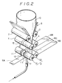
- Fig. 1 which shows the schematic arrangement of the apparatus according to the present invention
- the respective pairs of first pinch rolls 1 and second pinch rolls 2 are provided in the vertical direction, and a tubular raw material 10 delivered from an extruder, not shown, is threaded through spaces formed by these pinch rolls 1 and 2.
- This raw material 10 is formed of a single or multi-layer material of thermoplastic resin which is modified by such for example as polypropylene, polyethylene, a copolymer of ethylene-vinyl acetate, polyamide, polyester, a copolymer of ethylene-vinyl alcohol, polyvinylidene chloride resin, or a multi-layer material of thermoplastic resin denaturalized by an unsaturated carboxylic acid or a derivative thereof.
- Heating furnace 5 and stabilizing plates 6 having two plates and arranged into a generally V shape are respectively provided between the first and second pinch rolls 1 and 2.
- the first pinch rolls 1 are rotated about at the same circumferential speed as the speed at which the raw material is transferred and the second pinch rolls 2 are rotated at a faster circumferential speed than the first pinch rolls 1, so that the raw material 10 can be drawn in the direction of transferring the raw material (longitudinal direction) in cooperation with heating by the heating furnace 5.
- the raw material 10 is expanded by sealing of air and heating by the heating furnace 5, whereby the raw material 10 can also be drawn in the lateral direction thereof in the bubble shape, so that this raw material 10 can be produced as a film product drawn in the two axes at predetermined magnifications.
- air is blown to the raw material 10 with air rings, not shown, to stabilize the bubble during the drawing.
- the raw material 10 (a film) formed into the bubble shape with the stabilizing plates 6 is gradually flattened, the pinch rolls 2 approach to each other or are retracted from each other to thereby be opened or closed, and the two stabilizing plates 6 approach to each other or are retracted from each other in operational association with the second pinch rolls 2 to thereby be able to adjust a relative distance therebetween.
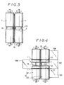
- the third pinch rolls 3 is constituted by: a cutting roll 31 made of rubber, having two detachable rotary blades 11 and a groove 12 formed on the outer peripheral surface thereof between the rotary blades 11 to form a nozzle insertion portion; and a receiving roll 32 made of metal, having two groove-shaped female blades 13 for receiving of the two rotary blades 11, respectively, and formed with a groove 12 on the outer peripheral surface thereof between the female blades 13 to form a nozzle insertion portion in cooperation with the groove 12 of the cutting roll 31.
- the raw material 10 When the tubular raw material 10 is threaded through a space formed between the rolls 31 and 32, the raw material 10 is cut in a doubled manner along the direction of transferring the raw material 10.
- the raw material 10 is cut into pieces or stripes including a first web-like piece or stripe 10A, and a second to fourth web-like pieces or stripes 10B, 10C and 10D, respectively.
- the first web-like piece 10A and the third web-like piece 10C as being single pieces, respectively, are separated from the second web-like piece 10B and the fourth web-like piece 10D as being in doubled state.
- the first web-like piece 10A after passing through the third pinch rolls 3 is taken up by a drum 21 to the left in Fig.
- intermediate pinch rolls 4 for taking up the raw material 10 delivered from the second pinch rolls 2 and delivering the same to the third pinch rolls 3, and having the same circumferential speed as the second pinch rolls 2.
- the intermediate pinch rolls 4 is constituted by a pair of rubber rolls for example, each having a narrowed-down portion 15.
- a rod-shaped nozzle 7 in such a manner as to be able to advance or retract through the groove of the third pinch rolls 3 and the narrowed-down portion 15 of the intermediate rolls 4.
- the nozzle 7 is connected to a tank 8 storing a large amount of compressed gas and a compressor 9, and can advance into the raw material 10 by use of its forward end formed into a tapered shape to thereby inject the gas.
- the flat tube-shaped raw material 10 transferred from the extruder is successively threaded through the spaces formed by the first pinch rolls 1, second pinch rolls 2, intermediate pinch rolls 4 and third pinch rolls 3 in the order described above, and the raw material 10 delivered from the third pinch rolls 3 is taken up by the drum 22 to the right in the drawings at a predetermined value of tension.
- the rotary blades 11 are previously mounted on the cutting roll 31 and the flat-shaped raw material 10 is cut into the web-like shapes in the doubled state while being pressed by the third pinch rolls 3.
- one of the web-like raw material or stripe 10A in the doubled state i.e.
- the web-like piece or stripe 10 is taken up by the other drum 21 at a predetermined value of tension.
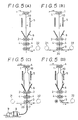
- the raw material 10 is divided into two including the first stripe 10A and the second to fourth stripes 10B - 10D, and the opening of the raw material is formed at a position thereof close to the third pinch rolls 3.
- the second pinch rolls 2 are separated from each other to open and the stabilizing plates 6 are spread in operational association with the rolls 2, thereafter, as shown in Fig. 5(C), the nozzle 7 advances into the raw material 10 from the opening 20 of the raw material up to the vicinity of a bottom portion of the second pinch rolls 2, passing through the groove 12 of the third pinch rolls 3 and the narrowed-down portion 15 of the intermediate pinch rolls 4, and the gas is injected into the raw material 10 through the forward end of the nozzle 7 by the tank 8 and the compressor 9.
- the raw material 10 being heated by the heating furnace 5 is expanded due to the injection of the gas to form the bubble, whereby the raw material 10 is expanded in the lateral direction thereof, and further, due to the difference in circumferential speed between the first pinch rolls 1 and the second pinch rolls 2, the raw material 10 is also drawn in the longitudinal direction thereof.
- the second pinch rolls 2 are made to approach to each other to close, the distance between the stabilizing plates 6 is reduced in the distance therebetween in operational association with the rolls 2, thereafter, the nozzle is retracted, and further, the cutting roll 31 is separated from the receiving roll 32 to thereby remove the cutting blades 11. Thereafter, as shown in Fig.
- the gas can be reliably injected into the raw material 10, and moreover, the nozzle 7 is advanced into the raw material 10 through the opening 20 of the raw material formed by separating the first web-like piece 10A and the remaining web-like pieces 10B - 10D, which are thus cut, and the grooves 12 are provided on the rolls 31 and 32 constituting the third rolls 3.
- mounting of the nozzle into the raw material 10 is facilitated to improve the workability and the size of the nozzle 7 is not restricted.
- the present invention can be applied to the tubularly drawing apparatus being large-sized and operated at high speed.
- the size of the tubular raw material 10 to be drawn is not restricted.
- the tubular raw material 10 is not spread at the cut portion as in the conventional example 1 and the raw material 10 is cut while being pressed by the third pinch rolls 3, no longitudinal cracks and wrinkles occur in the raw material 10.
- unsatisfactory cutting of the raw material 10 due to these cracks and wrinkles and damaged cutting blades can be prevented, thus enabling to avoid lowered safety due to these damages and the like.
- the provision of the intermediate rolls 4 between the second and third pinch rolls 2 and 3 makes it possible to secure the sufficient drawing force for drawing the raw material 10 in the longitudinal direction thereof in cooperation with the second and third pinch rolls 2 and 3.
- the gas when the gas is injected into the raw material 10, not only the second pinch rolls 2 but also stabilizing plates 6 consisting of the two plates can approach to each other and be separated from each other, so that, when these rolls and plates are separated from each other, the gas can be easily injected into the raw material 10, and, when these rolls and plates approach to each other, the raw material (film) can be taken up in the state where the raw material is sufficiently flattened.
- the groove-shaped female blades 13 are formed on the receiving roll 32 constituting the pair with the cutting roll 31 having the rotary blades 11, so that the tubular raw material 10 can be cut reliably. Further, the forward end portion of the nozzle 7 is tapered, whereby the nozzle 7 can advance smoothly into the tubular raw material 10, so that the workability can be improved.
- a tubular raw material 10 A water-cooled raw material having a thickness of 120 ⁇ m and a width (folded width) of 500mm which is obtained by extruding a raw material of polyamide (nylon) having a relative viscosity 3.75 from an extruder at a melting temperature of 250°C (Trade name: Ube nylon 1024).
- a ratio of speed between the first pinch rolls and the second pinch rolls (a draw ratio in the longitudinal direction): 3 A draw ratio in the lateral direction: 3
- a bubble was formed by injecting air according to the above embodiment, drawing was started and the tubular raw material 10 was drawn.
- a drawn film having a width of 1500mm was produced in one operation without any vibration of the tubular raw material 10.
- the raw material 10 was not cut as in the conventional example 2, and the gas was injected through an end portion of the raw material 10.
- the nozzle was inserted from the end portion of the raw material 10 and the gas was injected into the raw material 10 while the nozzle was moving together with the raw material 10.
- the width of the raw material 10 was set to 500mm as in the experimental example, however, the width of the film after the drawing was limited to 1100mm, and, even when the drawing operations were repeated several times, 1500mm at which the draw ratio in the lateral direction becomed three times was not achieved.
- the intermediate pinch rolls 4 were provided between the second and third pinch rolls 2 and 3, however, it is not necessarily required to provide the intermediate pinch rolls 4 according to the present invention.
- the rotary blades 11 formed on one of the third pinch rolls 3 are not limited to two as in the above embodiment only if the number of the rotary blades is plural.
- the cut position is not restricted to the one in the above embodiment.
- the cutting roll of the third pinch rolls 3 is not limited to rubber and the receiving roll 32 is not necessarily formed with the female blade 13.
- the nozzle insertion portion was formed into the groove 12, however, the nozzle insertion portion according to the present invention may be a space or the like between rolls divided into two at a predetermined position between the two rotary blades of the third pinch rolls 3 for example. Namely, any construction can be adopted only if the nozzle 7 can be inserted in a state where the cutting roll 31 and the receiving roll 32 of the third pinch rolls are in close contact with each other.
- a suitable cover may be provided in the circumferential directions of the rotary blades 11, to thereby avoid a danger.
- the present invention can offer such advantages that the gas can be reliably injected into the tubular raw material, the workabily during the injection is satisfactory and the size of the applicable tubular raw material is not restricted.
Landscapes
- Engineering & Computer Science (AREA)
- Mechanical Engineering (AREA)
- Physics & Mathematics (AREA)
- Geometry (AREA)
- Manufacturing & Machinery (AREA)
- Shaping By String And By Release Of Stress In Plastics And The Like (AREA)
- Extrusion Moulding Of Plastics Or The Like (AREA)
Applications Claiming Priority (2)
| Application Number | Priority Date | Filing Date | Title |
|---|---|---|---|
| JP227786/87 | 1987-09-11 | ||
| JP62227786A JPS6471727A (en) | 1987-09-11 | 1987-09-11 | Method and device for tubular orientation of thermoplastic resin |
Publications (3)
| Publication Number | Publication Date |
|---|---|
| EP0306958A2 EP0306958A2 (en) | 1989-03-15 |
| EP0306958A3 EP0306958A3 (en) | 1989-12-20 |
| EP0306958B1 true EP0306958B1 (en) | 1993-12-01 |
Family
ID=16866362
Family Applications (1)
| Application Number | Title | Priority Date | Filing Date |
|---|---|---|---|
| EP88114704A Expired - Lifetime EP0306958B1 (en) | 1987-09-11 | 1988-09-08 | Method of and apparatus for tubularly drawing thermoplastic resin |
Country Status (5)
| Country | Link |
|---|---|
| US (1) | US4869863A (ref) |
| EP (1) | EP0306958B1 (ref) |
| JP (1) | JPS6471727A (ref) |
| KR (1) | KR920002401B1 (ref) |
| DE (1) | DE3885982T2 (ref) |
Families Citing this family (9)
| Publication number | Priority date | Publication date | Assignee | Title |
|---|---|---|---|---|
| WO1989004244A1 (fr) * | 1987-11-12 | 1989-05-18 | Kohjin Co., Ltd. | Procede et installation de production de films etires |
| EP0675154B1 (en) | 1991-10-28 | 2000-06-07 | Idemitsu Petrochemical Co. Ltd. | Oriented film easy to split and method of producing the same |
| CA2077941C (en) * | 1992-07-07 | 2000-06-20 | John Louis Varadi | Automatic bubble blower for orientation film lines |
| ES2134264T3 (es) * | 1993-07-06 | 1999-10-01 | Aplicator System Ab | Dispositivo para alimentar fibras de refuerzo de productos plasticos termoestables. |
| US6395210B1 (en) | 1999-05-12 | 2002-05-28 | A&P Technology, Inc. | Pultrusion method and device for forming composites using pre-consolidated braids |
| NL1031597C2 (nl) * | 2006-04-13 | 2007-10-16 | Fuji Seal Europe Bv | Inrichting voor het uit een strook hoesvormig foliemateriaal vervaardigen van hoesvormige folie-omhullingen. |
| CN103203879B (zh) * | 2013-04-17 | 2015-03-11 | 常熟市冠日新材料有限公司 | 聚偏二氟乙烯薄膜的制备方法 |
| CN107263559B (zh) * | 2017-08-07 | 2018-11-23 | 胡海明 | 一种废塑料瓶再生制带器 |
| CN107214740B (zh) * | 2017-08-07 | 2018-10-16 | 胡海明 | 一种废塑料瓶再生自锁扎带制造器 |
Family Cites Families (13)
| Publication number | Priority date | Publication date | Assignee | Title |
|---|---|---|---|---|
| US2779973A (en) * | 1952-12-24 | 1957-02-05 | American Viscose Corp | Method and apparatus for forming continuous strips of sheet material from tubing |
| BE548151A (ref) * | 1955-06-03 | 1900-01-01 | ||
| US3482280A (en) * | 1967-03-16 | 1969-12-09 | Cupples Container Co | Method and apparatus for producing polymeric sheet |
| US3661482A (en) * | 1968-08-28 | 1972-05-09 | Stuart L Brown Jr | Apparatus for manufacturing biaxially oriented film with dimensional stability |
| GB1282062A (en) * | 1969-03-08 | 1972-07-19 | Showa Denko Kk | A method and apparatus for manufacturing a biaxially oriented cylindrical film |
| JPS55100124A (en) * | 1979-01-27 | 1980-07-30 | Chisso Eng Kk | Startup of bi-axial stretching for plastic tube and its apparatus |
| JPS55150326A (en) * | 1979-05-14 | 1980-11-22 | Asahi Chem Ind Co Ltd | Automatic blow-up device for resin tube |
| JPS5658831A (en) * | 1979-10-19 | 1981-05-22 | Polymer Processing Res Inst | Biaxial stretching apparatus of tubular film |
| JPS57163532A (en) * | 1981-04-01 | 1982-10-07 | Polymer Processing Res Inst | Method for orienting film to traverse direction mainly |
| DE3119006C2 (de) * | 1981-05-13 | 1983-09-01 | Windmöller & Hölscher, 4540 Lengerich | Vorrichtung zum Injizieren von Luft oder Gas in eine Schlauchfolienbahn |
| JP3301087B2 (ja) * | 1991-04-26 | 2002-07-15 | 松下電器産業株式会社 | 充電回路 |
| JPH05210155A (ja) * | 1992-01-30 | 1993-08-20 | Canon Inc | カメラ |
| JPH05216582A (ja) * | 1992-02-04 | 1993-08-27 | Fujitsu Ltd | コマンド選択方式 |
-
1987
- 1987-09-11 JP JP62227786A patent/JPS6471727A/ja active Granted
-
1988
- 1988-08-31 US US07/238,922 patent/US4869863A/en not_active Expired - Lifetime
- 1988-09-06 KR KR1019880011502A patent/KR920002401B1/ko not_active Expired
- 1988-09-08 DE DE88114704T patent/DE3885982T2/de not_active Expired - Fee Related
- 1988-09-08 EP EP88114704A patent/EP0306958B1/en not_active Expired - Lifetime
Also Published As
| Publication number | Publication date |
|---|---|
| DE3885982D1 (de) | 1994-01-13 |
| EP0306958A3 (en) | 1989-12-20 |
| EP0306958A2 (en) | 1989-03-15 |
| KR920002401B1 (ko) | 1992-03-23 |
| DE3885982T2 (de) | 1994-03-24 |
| KR890004849A (ko) | 1989-05-10 |
| JPH052498B2 (ref) | 1993-01-12 |
| US4869863A (en) | 1989-09-26 |
| JPS6471727A (en) | 1989-03-16 |
Similar Documents
| Publication | Publication Date | Title |
|---|---|---|
| DE3689306T2 (de) | Verfahren und Vorrichtung zum Extrudieren röhrenförmiger Folien. | |
| EP0306958B1 (en) | Method of and apparatus for tubularly drawing thermoplastic resin | |
| EP0247073B1 (en) | Plastic bag and method and apparatus of manufacture | |
| CN1196629C (zh) | 用于生产双腔室容器的设备 | |
| US12370732B2 (en) | Transporting a film tube, blown film line and method for producing a film | |
| US4434128A (en) | Method and apparatus for stretching thermoplastic polymer films | |
| US6231711B1 (en) | Methods and apparatus for making paint roller covers with thermoplastic cores | |
| CA1184104A (en) | Method for slitting and/or sealing plastic film material | |
| KR880003732A (ko) | 전기용접이 가능한 열가소성 관부재의 제조방법 및 제조장치 | |
| DE3513708C2 (de) | Extrusionskopf zur Herstellung doppelwandiger Kunststoffrohre mit zylindrischem Innenrohr und quergewelltem Außenrohr | |
| DE2252084A1 (de) | Verfahren zur kontinuierlichen herstellung einer folie aus einem geschaeumten thermoplastischen material | |
| US4931003A (en) | Apparatus for making biaxially stretched tubularly extended film with transverse closure strip | |
| US4842907A (en) | Biaxially stretched tubularly extruded film with transverse closure strip | |
| WO2007029386A1 (ja) | 管状樹脂フィルムの切断巻取り装置および切断巻取り方法 | |
| CH401454A (de) | Schlauchblasverfahren zur Herstellung von thermoplastischen Folien und Vorrichtung zur Durchführung des Verfahrens | |
| US5709599A (en) | Method for making heat-shrinkable tubular film material | |
| JPH11115046A (ja) | フィルム製造方法および装置 | |
| DE3888975T2 (de) | Verfahren und vorrichtung zum herstellen von verstärkter lage. | |
| JPH11504578A (ja) | 改良に係る、薄いlcp膜の製造方法 | |
| DE69313945T2 (de) | Automatisches Gebläse zur gerichteten Verstreckung von Blasfolien | |
| DE4012628C2 (de) | Verfahren und Vorrichtung zur Herstellung von biaxial gereckten nahtlosen thermoplatischen Schlauchfolien | |
| US4808099A (en) | Apparatus for making tubular film with transverse closure strips | |
| CA2287126C (en) | Methods and apparatus for making paint roller covers with thermoplastic cores | |
| EP0260848B1 (en) | Improvements in or relating to heat-shrinkable tubular film material | |
| TWI922283B (zh) | 擠出成膜裝置 |
Legal Events
| Date | Code | Title | Description |
|---|---|---|---|
| PUAI | Public reference made under article 153(3) epc to a published international application that has entered the european phase |
Free format text: ORIGINAL CODE: 0009012 |
|
| AK | Designated contracting states |
Kind code of ref document: A2 Designated state(s): BE CH DE FR GB IT LI NL SE |
|
| PUAL | Search report despatched |
Free format text: ORIGINAL CODE: 0009013 |
|
| AK | Designated contracting states |
Kind code of ref document: A3 Designated state(s): BE CH DE FR GB IT LI NL SE |
|
| 17P | Request for examination filed |
Effective date: 19900514 |
|
| 17Q | First examination report despatched |
Effective date: 19910604 |
|
| GRAA | (expected) grant |
Free format text: ORIGINAL CODE: 0009210 |
|
| AK | Designated contracting states |
Kind code of ref document: B1 Designated state(s): BE CH DE FR GB IT LI NL SE |
|
| ITF | It: translation for a ep patent filed | ||
| ET | Fr: translation filed | ||
| REF | Corresponds to: |
Ref document number: 3885982 Country of ref document: DE Date of ref document: 19940113 |
|
| PLBE | No opposition filed within time limit |
Free format text: ORIGINAL CODE: 0009261 |
|
| STAA | Information on the status of an ep patent application or granted ep patent |
Free format text: STATUS: NO OPPOSITION FILED WITHIN TIME LIMIT |
|
| 26N | No opposition filed | ||
| EAL | Se: european patent in force in sweden |
Ref document number: 88114704.5 |
|
| REG | Reference to a national code |
Ref country code: GB Ref legal event code: IF02 |
|
| PGFP | Annual fee paid to national office [announced via postgrant information from national office to epo] |
Ref country code: SE Payment date: 20020904 Year of fee payment: 15 |
|
| PGFP | Annual fee paid to national office [announced via postgrant information from national office to epo] |
Ref country code: CH Payment date: 20020916 Year of fee payment: 15 |
|
| PGFP | Annual fee paid to national office [announced via postgrant information from national office to epo] |
Ref country code: NL Payment date: 20020930 Year of fee payment: 15 |
|
| PGFP | Annual fee paid to national office [announced via postgrant information from national office to epo] |
Ref country code: BE Payment date: 20021129 Year of fee payment: 15 |
|
| PGFP | Annual fee paid to national office [announced via postgrant information from national office to epo] |
Ref country code: GB Payment date: 20030903 Year of fee payment: 16 |
|
| PG25 | Lapsed in a contracting state [announced via postgrant information from national office to epo] |
Ref country code: SE Free format text: LAPSE BECAUSE OF NON-PAYMENT OF DUE FEES Effective date: 20030909 |
|
| PGFP | Annual fee paid to national office [announced via postgrant information from national office to epo] |
Ref country code: FR Payment date: 20030909 Year of fee payment: 16 |
|
| PGFP | Annual fee paid to national office [announced via postgrant information from national office to epo] |
Ref country code: DE Payment date: 20030918 Year of fee payment: 16 |
|
| PG25 | Lapsed in a contracting state [announced via postgrant information from national office to epo] |
Ref country code: LI Free format text: LAPSE BECAUSE OF NON-PAYMENT OF DUE FEES Effective date: 20030930 Ref country code: CH Free format text: LAPSE BECAUSE OF NON-PAYMENT OF DUE FEES Effective date: 20030930 Ref country code: BE Free format text: LAPSE BECAUSE OF NON-PAYMENT OF DUE FEES Effective date: 20030930 |
|
| BERE | Be: lapsed |
Owner name: *IDEMITSU PETROCHEMICAL CO. LTD Effective date: 20030930 |
|
| PG25 | Lapsed in a contracting state [announced via postgrant information from national office to epo] |
Ref country code: NL Free format text: LAPSE BECAUSE OF NON-PAYMENT OF DUE FEES Effective date: 20040401 |
|
| EUG | Se: european patent has lapsed | ||
| REG | Reference to a national code |
Ref country code: CH Ref legal event code: PL |
|
| NLV4 | Nl: lapsed or anulled due to non-payment of the annual fee |
Effective date: 20040401 |
|
| PG25 | Lapsed in a contracting state [announced via postgrant information from national office to epo] |
Ref country code: GB Free format text: LAPSE BECAUSE OF NON-PAYMENT OF DUE FEES Effective date: 20040908 |
|
| PG25 | Lapsed in a contracting state [announced via postgrant information from national office to epo] |
Ref country code: DE Free format text: LAPSE BECAUSE OF NON-PAYMENT OF DUE FEES Effective date: 20050401 |
|
| GBPC | Gb: european patent ceased through non-payment of renewal fee |
Effective date: 20040908 |
|
| PG25 | Lapsed in a contracting state [announced via postgrant information from national office to epo] |
Ref country code: FR Free format text: LAPSE BECAUSE OF NON-PAYMENT OF DUE FEES Effective date: 20050531 |
|
| REG | Reference to a national code |
Ref country code: FR Ref legal event code: TP Ref country code: FR Ref legal event code: ST |
|
| PG25 | Lapsed in a contracting state [announced via postgrant information from national office to epo] |
Ref country code: IT Free format text: LAPSE BECAUSE OF NON-PAYMENT OF DUE FEES;WARNING: LAPSES OF ITALIAN PATENTS WITH EFFECTIVE DATE BEFORE 2007 MAY HAVE OCCURRED AT ANY TIME BEFORE 2007. THE CORRECT EFFECTIVE DATE MAY BE DIFFERENT FROM THE ONE RECORDED. Effective date: 20050908 |