EP0305035A2 - Lecteur à disques multiples résistant aux vibrations - Google Patents
Lecteur à disques multiples résistant aux vibrations Download PDFInfo
- Publication number
- EP0305035A2 EP0305035A2 EP88306172A EP88306172A EP0305035A2 EP 0305035 A2 EP0305035 A2 EP 0305035A2 EP 88306172 A EP88306172 A EP 88306172A EP 88306172 A EP88306172 A EP 88306172A EP 0305035 A2 EP0305035 A2 EP 0305035A2
- Authority
- EP
- European Patent Office
- Prior art keywords
- disc
- support member
- player
- turntable
- holder
- Prior art date
- Legal status (The legal status is an assumption and is not a legal conclusion. Google has not performed a legal analysis and makes no representation as to the accuracy of the status listed.)
- Granted
Links
Images


Classifications
-
- G—PHYSICS
- G11—INFORMATION STORAGE
- G11B—INFORMATION STORAGE BASED ON RELATIVE MOVEMENT BETWEEN RECORD CARRIER AND TRANSDUCER
- G11B33/00—Constructional parts, details or accessories not provided for in the other groups of this subclass
- G11B33/02—Cabinets; Cases; Stands; Disposition of apparatus therein or thereon
- G11B33/08—Insulation or absorption of undesired vibrations or sounds
-
- G—PHYSICS
- G11—INFORMATION STORAGE
- G11B—INFORMATION STORAGE BASED ON RELATIVE MOVEMENT BETWEEN RECORD CARRIER AND TRANSDUCER
- G11B17/00—Guiding record carriers not specifically of filamentary or web form, or of supports therefor
- G11B17/22—Guiding record carriers not specifically of filamentary or web form, or of supports therefor from random access magazine of disc records
- G11B17/30—Guiding record carriers not specifically of filamentary or web form, or of supports therefor from random access magazine of disc records wherein the playing unit is moved according to the location of the selected record
Definitions
- the present invention relates to a disc player, and more particularly to a multiple-disc player which is capable of storing a plurality of discs and playing back any desired succession of discs selected from the stored discs.
- the known multiple-disc player has a playback means including a turntable, a clamper a pickup, etc., a disc holder insertably mounted in a player housing for storing an array of successive discs perpendicularly to the disc carrying surface of the turntable, and a disc pickup/transfer mechanism for selecting desired discs, one at a time, from the disc holder, transferring the disc onto the disc carrying surface of the turntable, and returning the disc from the disc carrying surface back into the disc holder.
- the disc pickup/transfer mechanism moves the disc in two directions, i.e., a first direction parallel to the disc carrying surface of the turntable and a second direction normal to the first direction, i.e., the direction in which the discs are arrayed in the disc holder. More specifically, either one of the playback means and the disc holder is carried on a carriage not shown) which is reciprocally moved in the direction of the array of the discs by a driver means to move the disc in that direction. The disc is also moved in the direction parallel to the disc carrying surface of the turntable as follows:
- the disc holder is composed of a housing 1 in the form of a rectangular parallelepiped, and a plurality of flat trays 4 arrayed in the housing 1 in a direction (in the direction of the arrow Z and the direction opposite thereto) substantially normal to the disc carrying surface of the turntable, the trays 4 being rotatable about a support shaft 2 extending in the direction in which the trays 4 are arrayed.
- the trays 4 hold respectively discs 3 thereon in their major surfaces and are movable into and out of the housing 1 along their major surfaces.
- One of the discs 3 can be transferred, at a time, in one direction (parallel to the disc carrying surface of the turntable) simply by taking the tray 4 holding that disc 3 out of the housing 1.
- a pusher 6 is rotatably disposed laterally of the disc holder for engaging the trays 4 for pushing them out of the housing 1.
- a slider 7 is positioned near the disc holder for linear reciprocating movement. The slider 7 can be moved in an advancing direction by a certain driving force imparting means to enable a leading end 7a thereof to engage the pusher 6 for applying a moment to the pusher 6 thereby to turn the same.
- the overall playback means together with the carriage carrying the playback means, is reciprocably moved in the direction of the arrow Z and the direction opposite thereto for thereby relatively moving and positioning the trays 4 and the turntable in the direction in which the trays 4 are arrayed.
- the pusher 6 is turned to push one tray 4 out of the disc holder housing 1 for positioning the disc 3 in that tray on the turntable.
- two projecting pins 6a are mounted on the pusher 6 and slidably engage respectively in two arcuate guide slots 8a, 8b defined in the carriage (not shown) to guide the pusher 6 for its turning movement.
- the trays 4 are rotatable about an axis (which is the central axis of the support shaft 2) which is in alignment with the axis about which the pusher 6 is rotatable.
- the playback means is mounted on the support member by means of a vibration-resistant mechanism for protecting the playback means, which includes precision components such as the turntable and the pickup, from external vibrations.
- a vibration-resistant mechanism for protecting the playback means, which includes precision components such as the turntable and the pickup, from external vibrations.
- the trays 4 are in the form of thin plates. Consequently, when the tray 4 holding a disc 3 to be played back is pushed out of the housing 1, the tray 4 tends to be flexed in a direction normal to the disc carrying surface of the turntable. If the tray 4 projecting out of the housing 1 were flexed too much, the tray 4 would contact the playback means thereby damaging the disc being played back.
- a support mem ber on which a playback means including a turntable is mounted by a vibration-resistant mechanism is movable from an unretracted position to a retracted position with respect to a tray which is pushed out of a disc holder for a play-back process.
- the playback means is fixed with respect to a player housing by a lock mechanism.
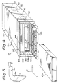
- a multiple-disc player according to the present invention is generally indicated at 101 in FIGS. 4 through 7.
- the multiple-disc player includes a player housing 102 which is substantially in the form of a rectangular parallelepiped.
- the player housing 102 includes a front panel 103 having a rectangular slot 103a defined therein for loading a magazine or disc holder 105 into the player housing 102, the slot 103a extending in lateral or leftward and rightward directions.
- the lateral or leftward and rightward directions used herein are defined as being perceived when one views the multiple-disc player, from back to front, in the direction of the arrow Y.
- the arrow X indicates the leftward direction
- the arrow Z indicates an upward direction.
- a lid 106 is swingably mounted on the font panel 103 by means of pins 103b (see FIGS.
- the slot 103a can be closed by the lid 106 when the lid 106 is turned about the pins 103b in the direction of the arrow F.
- a lock means for locking the lid 106 in the closed position, and a release button for releasing the lid 106 from the closed position will be described below.
- a finger 107a is mounted on the front panel 103 for engaging a free edge of the lid 106 to lock the same in the closed position.
- the finger 107a is reciprocally movable in the directions of the arrow G between an engaging position and a releasing position.
- the finger 107a is shown as being in the engaging position in FIG. 7.
- the finger 107a is normally urged to move into the engaging position by a spring 107b.
- the finger 107a and the spring 107b jointly provide a lock means for locking the lid 106 in the closed position.
- a release button 108 is disposed near the lock means for releasing the cover 106 from the engagement with the lock means.
- the release button 108 is swingably mounted on the front panel 103 for movement between an operated position and an unoperated position.
- the release button 108 has a free end engaging the finger 107a. More specifically, the release button 108 has a projecting support shaft 108a about which the release button 108 is swingable, the support shaft 108a being angularly movably disposed in a U-shaped bearing groove 103e defined in a rib 103d on the front panel 103.
- the bearing groove 103e has its depth-wise direction extending substantially perpendicularly to the directions in which the finger 107a is reciprocally movable.
- the support shaft 108a is prevented by the finger 107a from being dislodged from the bearing groove 103e.
- the spring 107b also serves to urge the support shaft 108a into the bearing groove 103e for thereby preventing the support shaft 108a from wobbling in the bearing groove 103e.
- the release button 108 is disposed in a cavity 103f defined on an outer side surface of the front panel 103 and extending in the leftward and rightward directions (i.e., the direction of the arrow X and the direction opposite thereto) in the vicinity of the lid 106. Therefore, the release button 108 is less likely to be touched by a human body or an object against the intention of the operator.
- the cavity 103f is disposed above the lid 106 so that the lid 106 which turns about its lower edge will not interfere with operation of the release button 108.
- the cavity 103f has a V-shaped cross section normal to the directions in which the cavity 103f extends (i.e., the direction of the arrow X and the direction opposite thereto).
- the release button 108 is located in an upper portion of the cavity 103f, i.e., on the upper side of the V shape. This arrangement allows the operator to have a finger touch the release button 108 from the upper side when the player is placed within a trunk room of an automobile. The push which is applied by the finger to operate the release button 108 is directed obliquely upwardly, the release button 108 can be operated highly easily effectively.
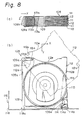
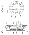
- the magazine 105 has a magazine casing 109 in the form of a flat rectangular parallelepiped as a whole, and a total of six alternate rectangular plate-like trays A111 and B112, divided into two groups each containing three trays, for holding respective discs 110 in their major surfaces.
- the trays A111, B112, and hence the discs 110 are arrayed at a predetermined pitch in directions normal to the disc carrying surface of a turntable (described later on), i.e., in vertical directions (the direction of the arrow Z and the direction opposite thereto).
- the trays A111, B112 are rotatably supported on a support shaft 109a disposed at the righthand left end of the magazine casing 109 and extending vertically in the directions in which the trays are arrayed, so that the trays A111, B112 can move into and out of the magazine casing 109 along the respective major surfaces.
- the magazine casing 109 has seven partitions 109b which are spaced vertically in the direction of the arrow Z and the direction opposite thereto.
- the trays A111, B112 are disposed between the partitions 109b.
- the partitions 109b have respective small circular concentric openings or holes 109c defined therein near the support shaft 109a.
- FIGS. 10 and 11 show the trays A111, B112 in detail.
- the trays have holes or openings 111a, 112a which can be brought into registry with the openings 109c defined in the partitions 109b.
- each of the spherical movable elements 113a is equal to the pitch at which the alternate trays 111, 112 are spaced
- the spherical movable elements 113a are normally urged against each other by a pair of leaf springs 113b disposed on the upper and lower ends of the magazine casing 109.
- a presser lever 114 is disposed in the lefthand front end of the magazine casing 109 and extends substantially in the fore-and-aft directions (the direction of the arrow Y and the direction opposite thereto).
- the presser lever 114 has a front end swingably attached to the magazine casing 109 by means of a pin 114a which extends vertically in the direction of the arrow Z and the direction opposite thereto.
- the other end, or rear end, of the presser lever 114 can smoothly engage the free ends of the trays 111, 112.
- a spring 114b engages the presser lever 114 for normally urging the presser lever 114 counterclockwise in FIG. 8(b) to enable the presser lever 114 to push the trays.
- the presser lever 114 and the spring 114b jointly serve as a presser means for pressing the trays 111, 112 into a storage position in the magazine casing 109 and toward the support shaft 109a.
- the presser means, the openings 109c defined in the partitions of the magazine casing 109, the openings 111a, 112a defined in the trays 111, 112, the spherical movable elements 113a, and the leaf springs 113b jointly constitute a click mechanism for locking the trays 111, 112 in the storage position in the magazine casing 109.
- the trays 111, 112 are of substantially the same shape except that they have respective ledges 111b, 112b of different shapes and in different positions, which can be engaged by a fingertip for pulling the trays out of the magazine casing 109.
- the trays 111, 112 have recesses 111c, 112c defined in their free ends and in which the presser lever 114 can engage.
- a chassis 116 serving as a support member is disposed in the player housing 102.
- the chassis 116 is suspended in the player housing 102 by four coil springs 117 serving as resilient members.
- a playback means and a disc pickup/transfer mechanism are mounted on the chassis 116.
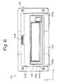
- the chassis 116 is in the form of a rectangular parallelepiped having an open front end (in the direction of the arrow Y). As illustrated in FIGS.
- a decorative panel 118 is attached to the front end of the chassis 116, and has a rectangular magazine insertion hole 118a for the insertion therethrough of the magazine 105 which has been placed through the slot 103a in the front panel 103. As shown in FIG. 8(b), the magazine 105 is completely loaded when it is fully inserted into the magazine insertion hole 118a.
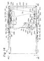
- each of the air dampers 120 comprises a flat viscoelastic hollow member 120a made of rubber or the like and having two confronting openings, and a pair of disc-shaped rigid members 120b, 120c closing the openings, respectively.
- One of the rigid members 120b comprises a steel plate fixed to the chassis 116 by means of a small screw 120d.
- the other rigid member 120c has a central air hole 120e through which air can be introduced into and discharged from the viscoelastic hollow member 120a.
- the viscoelastic hollow member 120a has an annular recess 120f defined in its inner surface and extending around one of the openings in which the rigid member 120b is fitted.
- the viscoelastic hollow member 120a is elastically deformed as indicated by the two-dot-and-dash lines in FIG. 12 as the chassis 116 moves in the direction of the arrow H, forcing air to flow into and out of the viscoelastic hollow member 120a through the air hole 120e, so that the vibratory energy of normal magnitude can be absorbed.
- a peripheral edge 120g of the opening in which the rigid member 120b is fitted is forced to collide with an inner side surface 120h of the confronting rigid member 120c, for thereby absorbing the vibratory shock in a rather abrupt fashion.
- the annular recess 120f allows the peripheral edge 120g to bump the confronting surface smoothly and effectively.
- a carriage 123 is disposed on a front half portion of the chassis 126 for caring the magazine 105 which has been inserted into the player housing 102.
- the carriage 116 is mounted on the chassis 116 so as to be movable vertically in the directions in which the trays 111, 112 are arrayed in the magazine 105 (the direction of the arrow Z and the direction opposite thereto).
- the carriage 123 is substantially of a rectangular parallelepiped having open front and rear ends to allow the magazine 105 to be inserted into the carriage 123.
- a pair of longitudinally movable plates 125, 126 serving as movable members is disposed in the chassis 116 and extend parallel to each other along the fore-and-aft directions in sandwiching relation to the carriage 23 in the lateral directions.
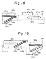
- FIGS. 18 and 19 show the movable plates 125, 126.
- the movable plates 125, 126 have guide grooves 125a, 126a defined respectively therein and extending longitudinally of the movable plates 125, 126.
- the movable plates 125, 126 are attached to the chassis 116 for reciprocating movement in the fore-and-aft directions, by pins 116a projecting from the chassis 116 and slidably fitted in the respective guide grooves 125a, 126a.
- the carriage 123 sandwiched between the movable plates 125, 126 has three projecting pins 123a, one on the lefthand side thereof and two on the righthand side thereof. As shown in FIGS. 15 and 16, these pins 123a are slidably fitted in respective guide grooves 116b defined vertically in the chassis 116 (in the direction of the arrow Z and the direction opposite thereto) for vertically guiding the car riage 123.
- the pins 123a on the carriage 123 slidably extend through the guide grooves 116b in the chassis 116 and also cam grooves 125c, 126c defined in the movable plates 125, 126.
- the cam groove 125c defined in the lefthand movable plate 125 is inclined as a whole downwardly (in the direction opposite to the direction of the arrow Z) in the forward direction (indicated by the arrow Y).
- the paired cam grooves 126c defined in the righthand movable plate 126 are inclined as a whole upwardly in the forward direction.
- the cam grooves 125c, 126c are shaped to allow the carriage 123 to be moved vertically in response to relative reciprocating movement of the movable plates 125, 126.
- the cam grooves 125c, 126c have six straight portions 125d, 126d, respectively, extending in the directions (fore-and-aft directions) in which the movable plates 125, 126 are movable, and five inclined portions 125e, 126e continuous to the straight portions 125d, 126d and slanted with respect to the straight portions 125d, 126d. Therefore, the cam grooves 125c, 126d are shaped like staircases as a whole. As shown in FIGS. 14, 15, and 18, the movable plate 125 disposed leftwardly of the carriage 123 has six recesses 125g defined as engaging portions in an upper edge thereof at equal pitches corresponding to the respective straight portions 125d.
- a pin 128b made of resin is disposed on a free end of a leaf spring 128 fixed as a resilient member to the lefthand outside surface of the chassis 116 by a screw 128a, and can engage one, at a time, of the recesses 125g under the resiliency of the leaf spring 128.
- the leaf spring 128 urges the cam surface of the cam groove 125c defined in the movable plate 125 to be pressed against the pin 123a of the carriage 123 for preventing the carriage 123 from wobbling due to the dimensional tolerances of the cam groove 125c and the pin 123a even if external vibration is applied to the disc player.
- the movable plate 125 is highly accurately be held in a selected one of vertical positions since the pin 128b on the free end of the spring 128 engages a corresponding one of the six recesses 125g in the movable plate 125 under the resilient force of the leaf spring 128.
- the movable plate 125 on the lefthand side of the carriage 123 has a rack 125i on its front end, the rack 125i extending in the direction in which the movable plate 125 is movable.
- the rack 125i is held in mesh with a final gear 130a of a speed reducer mechanism 130.
- the speed reducer mechanism 130 includes a first gear 130b meshing with a small gear 131a fitted over the output shaft of a motor 131. When the motor 131 is energized to rotate the output shaft in one direction or the other, the movable plate 125 is reciprocally moved. As shown in FIG.
- a turn lever 132 is disposed between the movable plates 125, 126 and angularly movably supported at its center on the chassis 126 by a support shaft 132a extending vertically (in the direction of the arrow Z and the direction opposite thereto).
- the turn lever 132 has on its opposite ends respective projecting pins 132b, 132c smoothly movably mounted on respective arms 125j, 126j on the movable plates 125, 126 for smooth pivotal movement.
- the motor 131, the speed reducer mechanism 130, the turn lever 132, and small parts associated therewith jointly constitute a driving force imparting means for applying a driving force to the movable plates 125, 126 to move these movable plates 125, 126.
- swing levers 134, 135 are swingably mounted on the lateral outer sides of the chassis 116 by means of respective pins 134a, 135b.
- the swing levers have free ends pivotally coupled to respective two of the pins 123a on the carriage 123.
- respective coil springs 134b, 135b for normally biasing the pins 123a and hence the carriage 123 upwardly in the direction of the arrow Z. Therefore when the motor 131 is rotated in a direction to move the carriage 123 upwardly against gravity, the ascending movement of the carriage 123 is assisted by the resilient forces of the coil spring 134b, 135b which are applied through the swing levers 134, 135.
- the magazine 105 has a recess 105a of a rectangular crosssectional shape defined in the righthand side surface thereof.
- the carriage 123 has a lock member 137 disposed therein for engaging in the recesse 105a to lock the magazine 105 in the loaded position.
- the lock member 137 is swingably attached to the carriage 123 by means of a vertically extending support shaft 137a, and has a finger 137b on its free end for engaging in the recess 105a.
- a spring 137c is mounted on the support shaft 137a for normally urging the lock member 137 in a direction to engage in the recess 105a.
- an upwardly extending pin 137d disposed on the lock member 137 projects through a small opening 123c defined in the upper panel of the carriage 123 into a position above the carriage 123.
- a tapered portion 126h on the movable plate 126 disposed rightwardly of the carriage 123 can engage the pin 137d.
- the tapered portion 126h engages the pin 137d to displace the lock member 127 out of the recess 105a of the magazine 105.
- a magazine ejecting means for ejecting the magazine 105 as it is unlocked from the lock member 137 from the player housing 102 by a certain distance under the resilient force of a spring to allow the disc player operator to retrieve the magazine 105.
- a loading detector means for detecting when the magazine 105 inserted into the player housing 102 is loaded in its storage area will be described below.
- a detector lever 139 is swingably mounted by a support shaft 139a at the righthand end portion of the carriage 123 holding the inserted magazine 105, i.e., at the deepest portion of the storage area.
- the detector lever 139 is normally biased by a coil spring 139b.
- the detector lever 129 has on its free end an abutment 139c which can be engaged by the leading end of the magazine 105 as it is inserted.
- a detector switch 140 is disposed on the carriage 123 on the lefthand side of the detector lever 139 and has an actuating arm which can be engaged by a raised portion 139d on the detector lever 139.
- the carriage 123 also supports thereon another detector switch 141 disposed in front of the detector switch 140.
- the detector switch 141 is triggered when one end of an L-shaped detector lever 142 swingably attached to the carriage 123 by a support shaft 142a engages the actuating arm of the detector switch 141.
- the other end of the detector lever 142 is pivotally mounted on the pin 137d on the lock member 137. When the lock member 137 locks the magazine 105 in position, the detector lever 142 engages the detector switch 141.
- the detector switch 141 serves as a first detector switch, and the detector switch 140 as a second detector switch.
- the magazine loaded condition is reliably detected by these first and second detector switches. Only when the magazine loaded condition is detected, a disc loading process and a disc playback process are started in response to a playback command signal. When the magazine loaded condition is not detected, a disc loading process and a disc playback process are not initiated even if a playback command signal is applied.
- the detector switches 140, 141 and the detector levers 139, 142 jointly serve as a loading detector means for detecting when the magazine 105 is loaded into its storage area.
- an address plate 144 is integrally formed on a central upper edge of the movable plate 125, the address plate 144 having a plurality of, e.g., five slits 144a defined in line along the direction in which the movable plate 125 is movable.
- a photosensor 145 is provided in alignment with the array of slits 144a for detecting the slits 144a.
- a slit detecting signal produced from the photosensor 145 is sent to a counter (not shown) which counts such slit detecting signals.
- a control unit (not shown) for automatically controlling the multiple-disc player determines the position where the movable plate 125 is stopped from the count of the counter.
- FIG. 17 shows the bottom of the internal structure of the multiple-disc player.
- a subchassis 148 is fixed to a rear half portion of the chassis 116.
- a pusher 149 is disposed on the righthand front end of the subchassis 148 for engaging one, at a time, of the trays 111, 112 in the magazine 105 to push the tray out of the magazine 105.
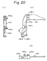
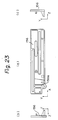
- the pusher 149 is illustrated in FIGS. 20(a) through 20(c) in greater detail. As can be seen from FIGS.
- the pusher 149 is substantially L-shaped as a whole and has a pair of pins 149a which slidably engages in respective arcuate guide grooves 148a, 148b (see FIG. 17) defined in the subchassis 148 for guiding the pusher 149, the guide grooves 148a, 148b having different radii of curvature. More specifically, the pusher 149 rotates about the axis aligned with the center of curvature of the arcuate guide grooves 148a, 148b to enable a finger 149c on one end thereof to push one, at a time, of the trays 111, 112 out of the magazine 105.
- the axis about which the pusher 149 is rotatable i.e., the center of curvature of the arcuate guide grooves 148a, 148b is aligned with the axis about which the trays 111, 112 are rotatable, i.e., the support shaft 109a shown in FIGS. 8(b).
- Each of the trays 111, 112 can be pushed out of the magazine 105 by the pusher 149 engaging a portion 111d, 112d (see FIGS. 8(b), 10, and 11) of the tray near the support shaft 109a.
- a substantially disc-shaped intermediate lever 151 is rotatably mounted on the subchassis 148 behind the pusher 149 by means of a pin 151a.
- the intermediate lever 151 is shown in FIGS. 21(a) through 21(c) in more detail.
- the intermediate lever 151 has an internal gear 151b meshing with a gear 152a integral with worm wheel 152b held in mesh with a worm 152c mounted on the output shaft of a motor 153. Therefore, the intermediate lever 151 is rotated by the motor 153 through the train of these gears.
- a slider 155 and a lever 156 which extend in the lateral directions are disposed on the righthand front end of the subchassis 148 in vertically overlapped relation.
- the slider 155 and the lever 156 are movably mounted on the subchassis 148 by means of a plurality of pins (not shown) for reciprocating movement in their longitudinal directions or lateral directions (the direction of the arrow X and the direction opposite thereto).
- FIGS. 22(a) through 22(c) show the slider 155 in detail
- FIGS. 23(a) through 23(c) illustrate the lever 156 in detail. As shown in FIGS.
- the intermediate lever 151 has a projecting pin 151d on one end which is slidably fitted in an oblong hole 156a defined in the righthand end of the lever 156 and extending in the fore-and-aft directions (the direction of the arrow Y and the direction opposite thereto).
- the motor 153 is rotated in one direction or the other to turn the intermedi ate lever 151 in one direction or the other, the lever 156 is moved to the left or right (the direction of the arrow X or the direction opposite thereto).
- the slider 155 has one end in its direction of reciprocating movement, i.e., a righthand end (in the direction opposite to the direction of the arrow X) thereof serving to engage the pusher 149 to rotate the same.
- the lever 156 superposed on the slider 155 converts a rotative force of the intermediate lever 151 into a linear force which is applied to the slider 155.
- a lock/unlock means is disposed between the slider 155 and the lever 156 for locking the slider 155 and the lever 156 with respect to each other, and also for unlocking them from each other when the slider 155 and the lever 156 as they are locked are moved in the forward direction to the right (in the direction opposite to the direction of the arrow X) until the slider 155 reaches its most advanced position in the forward direction (i.e., the position in which the pusher 149 turned by the slider 155 pushes one of the trays 111, 112 fully out of the magazine 105).
- the coil spring 157 shown in FIG. 17 serves as part of the lock/unlock means.
- the details of the lock/unlock means is disclosed in Japanese Patent Publication No. 61-261853, for example, and will not be described here in detail.
- the pusher 149 has an angular groove 149e defined in an end thereof, and a projecting pin 155b disposed on a leading end of the slider 155 in the forward direction of its movement slidably engages in the angular groove 149e.
- movement of the slider 155 in the forward direction causes the pin 155b of the slider 155 to engage the bent portion of the angular groove 149e for thereby enabling the pusher 149 to start being angularly moved.
- the pusher 149 has a projection 149f extending radially outwardly of the angular groove 149e with respect to the center of rotation of the pusher 149.
- the slider 155 has an arm 155d disposed on its leading end in the forward direction of its movement for engaging the projection 149f.
- the arm 155d engages the projection 149f only during a small period immediately after the slider 155 starts moving in the forward direction, i.e., during an initial period of tray pushing stroke.
- this engagement between the arm 155d and the projection 149f applies a large moment to the pusher 149 regardless of the fact that a relatively small driving force is imposed on the slider 155.
- the trays 111, 112 are easily released from the click mechanism (which comprises the spherical movable elements 113a and the leaf springs 113b shown in FIGS. 8 and 9) disposed in the magazine 105.
- the click mechanism which comprises the spherical movable elements 113a and the leaf springs 113b shown in FIGS. 8 and 9 disposed in the magazine 105.
- the pusher 149 is continuously turned by a small moment applied to the pusher 149 only by the engagement of the pin 155b of the slider 155 in the angular groove 149e in the pusher 149 for pushing one of the trays 111, 112 fully out of the magazine 105.
- the motor 153 and a speed reducer mechanism which act as a driving force applying mechanism for applying a driving force to the slider 155 may be small in size, so that the entire disc player may be reduced in side and consume a reduced amount of electric power.
- the angular groove 149e is of such a bent configuration that the pusher 149 will reliably be returned to its starting position (shown in FIG. 17) by the pin 155b engaging in the angular groove 149e without any biasing forces from any spring when the slider 155 is moved back (in the direction of the arrow X).
- FIGS. 7 and 15 a base 160 in the form of a steel plate is fixed to the inner surface of a rear upper portion of the chassis 116.
- FIG. 25 is a view taken along line IIXV - IIXV of FIG. 15, and
- FIG. 26 is a view taken along line IIXVI - IIXVI of FIG. 25.
- a support member 166 is attached to the lower surface of the base 160 by a link mechanism or holder mechanism comprising a plurality of pins 161, 162 and swing arms 163, 164.
- the support member 166 can move prescribed distances in the fore-and-aft directions (the direction of the arrow Y and the direction opposite thereto) and also in the vertical directions (the direction of the arrow Z and the direction opposite thereto).
- FIG. 27 shows in side elevation the base 160 only which is illustrated in FIG. 26, and
- FIG. 28 shows in side elevation the support member 166 only which is illustrated in FIG. 26.
- a mechanism chassis 168 is mounted on the support member 166 through a vibration-resistant mechanism comprising four viscoelastic members 167.
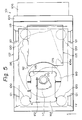
- the mechanism chassis 168 is also shown in FIG. 5.
- a turntable 170 is mounted on the mechanism chassis 168, which supports thereon a carriage 171 housing an optical pickup means.
- the carriage 171 is guided by a guide shaft 172 for movement in the fore-and-aft directions (the direction of the arrow Y and the direction opposite thereto) in a plane including the disc carrying surface of the turntable.
- a carriage driving means is also mounted on the mechanism chassis 168 for moving the carriage 171.
- the mechanism chassis 168, the turntable 170, the carriage 171 including the optical pickup means, and the carriage driving means constitute a playback means for playing back discs.
- the entire playback means is supported on the support member 166 (shown in FIGS. 25, 26, and 28) through the vibration-resistant mechanism composed of the viscoelastic members 167.
- the playback means and the support member 166b are mounted on the base 160 through the link mechanism for movement by prescribed distances in the fore-and-aft directions (the direction of the arrow Y and the direction opposite thereto) and also in the vertical directions (the direction of the arrow Z and the direction opposite thereto).
- the playback means and the support member 166 are vertically movable by about 3 mm , for example, in response to operation of the link mechanism.
- the disc carrying surface of the turntable 170 lies perpendicularly to the vertical directions (the direction of the arrow Z and the direction opposite thereto) in which the playback means and the support member 166b are movable, i.e., parallel to a plane including the fore-and-aft directions and the lateral directions (the direction of the arrow X and the direction opposite thereto).
- the playback means and the support member 166 are made movable perpendicularly to the disc carrying surface of the turntable 170 for the reasons described below.
- the tray 111 which projects out of the magazine 105 is in the form of a thin plate, as shown in FIGS. 5 and 26, the tray 111 is liable to be flexed transversely in the vertical directions when it is pushed out of the magazine 105. If the tray 111 is flexed or deformed to a large extent upwardly in the direction of the arrow Z, the tray 111 would contact the playback means including the turntable 170. To avoid this, when the tray 11 is pushed out of the magazine 105, the playback means is retracted in the direction in which the tray 111 is flexed, by a distance which is greater than the amount of flexing of the tray 111. In FIG.
- the support member 166 is shown as being in an unretracted position where the support member 166 is not yet retracted with respect to the tray 111 to be pushed out of the magazine 105.
- the support member 166 can be moved about 3 mm upwardly (in the direction of the arrow Z) into a retracted position.
- FIGS. 5, 25, and 26 a pair of laterally spaced downwardly extending shafts 175 is fixed to the lower surface of a rear end of the mechanism chassis 168 which directly supports the playback means including the turntable 170.
- the shafts 175 are held in slidable contact with the rear end of the subchassis 148 (see FIGS. 7, 17, and 26) which is positioned downwardly of the mechanism chassis 168.
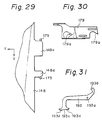
- FIG. 29 shows in plan the manner in which the shafts 175 slidably engages the subchassis 148. As can be seen from FIG. 29.
- the shafts 175 are slidably held in contact with tongues 148d, 148e projecting from the rear end of the subchassis 148 in the direction opposite to the direction of the arrow Y.
- the engagement between the shafts 175 and the tongues 148e, 148d is effective in preventing the mechanism chassis 168 from which the shafts 175 project and also the support member 166 supporting the mechanism chassis 168 from slightly moving in the lateral directions (the direction of the arrow X and the direction opposite thereto).
- the link mechanism interposed between the support member 166 and the base 160 is a highly delicate mechanism and the rigidity of the overall link mechanism is not so large.
- the link mechanism might be distorted to move the support member 166 held thereby into collision with other components.
- the support member 166 is prevented from abruptly moving under shocks since the shafts 175 projecting from the mechanism chassis 168 supported on the support member 166 are held in slidable contact with the tongues 148d, 148C of the subchassis 148 at all times.
- a support member driving means for driving the support member 166 in response operation of the link mechanism will be described below.
- a pair of lock plates 178, 179 is disposed in sandwiching the support member 166 in the lateral directions.
- the lock plates 178, 179 are attached to the support member 166 by pins 166a for reciprocating movement by a certain interval in the fore-and-aft directions (the direction of the arrow Y and the direction opposite thereto).
- the lock plate 179 shown in FIG. is illustrated in FIG. 30).
- the other lock plate 178 is substantially identical in configuration to the lock plate 179.
- the lock plate 179 has engaging portions 179a, 179b engageable with two lock shafts 168a projecting from the righthand end of the mechanism chassis 168 on which the turntable 170 and others are directly carried.
- the other lock plate 178 has an engaging portion engageable with a lock shaft 168b projecting from the lefthand end of the mechanism chassis 168.
- a pair of mutually crossing levers 181, 182 extending in the lateral directions is disposed on the front end of the support member 166.
- the levers 181, 182 are swingably mounted at ends thereof to the support member 166 by means of respective pins 181a, 182a.
- the other ends of the levers 181, 182 are pivotally mounted on the front ends of the lock plates 178, 179 by respective pins 181b, 182b.
- the levers 181, 182 are pivotally coupled to each other by a pin 183 at their intermediate portions.
- a rectangular movable plate 184 is disposed in front of the levers 181, 182, and mounted on the chassis 116 by a pin 184a for reciprocating movement in the fore-and-aft directions (the direction of the arrow Y and the direction opposite thereto).
- the movable plate 184 has a projecting pin 184b rotatably fitted in a slot 181d defined in the lever 181.
- the movable plate 184 can be moved by a motor 187 through a coupling mechanism 185 and a speed reducer mechanism 186.
- the lock plates 178, 179 are moved in the forward and rearward directions through the speed reducer mechanism 186, the coupling mechanism 185, the movable plate 184, and the levers 181, 182.
- the lock plates 178, 179 then engage the lock shafts 168a, 168b to transmit a driving force to the mechanism chassis 168 which applies the driving force via the four viscoelastic members 167 to the support member 166.
- the link mechanism is now operated to move the support member 166.
- the motor 187, the speed reducer mechanism 186, the coupling mechanism 185, the movable plate 184, the levers 181, 182, and the lock plates 178, 179 jointly provide a support member driving means for moving the support member 166.
- the lock plates 178, 179 serve to lock the playback means to the player housing 102 when the support member 166 is in the unretracted position (shown in FIG. 26) with respect to the tray 111 pushed out of the magazine 105.
- the lock plates 178, 179 locks the playback means by holding the engaging portions 179a, 179b in engagement with the lock shafts 168a, 167b on the mechanism chassis 168 that serves as a base member of the playback means. Under this condition, therefore, the playback means is prevented from moving even slightly even if a relatively large shock is applied to the disc player.
- a pair of laterally spaced brackets 168d is disposed on the rear end of the mechanism chassis 168, and a support body 189 is swingably attached to the brackets 168d by support pins 168e.
- the support pins 168e extend in the lateral directions (the direction of the arrow X and the direction opposite thereto) for causing the support body 189 substantially in the vertical directions (the direction of the arrow Z and the direction opposite thereto), i.e., within a plane normal to the disc carrying surface of the turntable 170 (shown in FIG. 5).
- a disc-shaped presser 190 is rotatably mounted on a free end of the support body 189 for abutting against the surface of the disc 110, confronting the disc carrying surface of the turntable 170, remote from the disc carrying surface, and for pressing the disc 110 against the disc carrying surface of the turntable 170.
- a coil spring is provided for normally urging the support body 189 in a direction to displace the presser 190 toward the disc carrying surface of the turntable 170.
- a roller 189a is mounted on the distal end of the support body 189 in rolling contact with a cam 151f on the intermediate lever 151 shown in FIGS. 17 and 21. Therefore, upon turning movement of the intermediate lever 151, the support body 189 is swung under the resiliency of the coil spring.
- the intermediate lever 151, the driving means including the motor 153 for rotating the intermediate lever 151, the support body 189, and the coil spring (not shown) jointly serve as a presser moving means for mounting the presser 190 on and dismounting the presser 190 from the disc carrying surface of the turntable 170.
- the presser moving means and the presser 190 constitute a disc clamp mechanism for clamping a disc on the turntable 170. As described above, the disc 110 carried on the tray 112 pushed out of the magazine 105 is lifted by the disc clamp mechanism for a prescribed interval, and then mounted and clamped on the disc carrying surface of the turntable 170.
- FIGS. 25 and 26 a pair of holders 193 is swingably attached by respective pins 193a to the lateral side panels of the support member 166 on which the playback means including the turntable 170 is supported by the four viscoelastic members 167.
- FIG. 31 shows one of the holders 193 in side elevation.
- the holders 193 serve as a disc holder means for cooperating with the presser 190 of the disc clamp mechanism in sandwiching the disc 110 lifted by the presser 190.
- the holders 193 are swingable in a plane normal to the disc carrying surface of the turntable 170, as is the case with the support body 189 of the disc clamp mechanism. As illustrated in FIGS.
- each of the holders 193 has an arm 193b on a free end thereof which is smoothly held against a bearing portion 160a on the base 160 by a biasing plate 195 which is urged by a spring 194 (see FIG. 26 in particular).
- the holder 193 is swung in response to movement of the support member 166 with respect to the base 160, for moving another free end of the holder 193 into and out of the disc carrying surface of the turntable 170.
- the free end of the holder 193 which can thus move into and out of the disc carrying surface has a disc engaging surface 193d for abutting against the disc 110.
- the disc engaging surface 193d has a certain curvature in the directions in which the holder 193 is swingable, for permitting smooth abutting engagement with the disc 110.
- Two members 193d of a high coefficient of friction are disposed on the disc engaging surface 193c for abutting against the surface of the disc 110 to prevent the disc 110 from being displaced radially while the holder 193 is swinging.
- the disc holder means comprising the disc holders 193 serves to keep the disc 110, which has been lifted by the disc clamp mechanism, parallel to the disc carrying surface of the turntable 170, and also to prevent the disc 110 from being displaced radially. Since the disc holder means is operated by the driving force from the support member driving means (described above), no dedicated driving means for driving the disc holder means is necessary, so that the disc player is small in overall size and low in cost, and the electric power consumption which would otherwise be required by a motor or the like used as such a dedicated driving means can be eliminated.
- the magazine carriage 123, the driving means for moving the carriage 123, the movable plates 125, 126, the driving force imparting means including the motor 131 for imparting a driving force to the movable plates 125, 126, the pusher means including the pusher 149 for pushing the trays 111, 112 out of the magazine 105, the disc clamp mechanism, the disc holder means including the holders 193, and associated small components jointly constitute a disc pickup/transfer mechanism for successively selecting desired discs from the magazine 105 and transferring one disc, at at time, onto the disc carrying surface of the turntable 10.
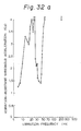
- FIG. 32(a) shows data on the vibration absorbing effect of the air dampers 121 interposed between the side ends of the chassis 116 and the player housing 102 on laterally applied vibration.
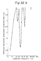
- FIG. 32(b) shows data on the vibration absorbing effect of ordinary rubber dampers used in place of the air dampers 121.
- the term "vibration-resistant threshold acceleration" used in the graphs of FIGS. 32(a) and 32(b) means the value of threshold vibratory acceleration beyond which the disc player would fail to properly reproduce the recorded material from the disc because of skipping some of the recorded material.
- FIG. 33 illustrates data on the vibration-absorbing effect of the other air dampers 120 disposed between the upper end of the chassis 116 and the player housing 102 on vertically applied vibration.
- Signals issued from the detector switches as described above are supplied to the control unit (CPU) which generates operation signals to operate the motors 131, 153, 187, and a turntable spindle motor 170.
- CPU control unit
- the multiple-disc player of the foregoing construction is installed in the trunk of an automobile.
- the operator opens the lid 106 and insert the magazine 105 through the opening 103a into the player.
- a selected disc can be loaded, played back, and unloaded in the multiple-disc player by energizing the motors in a predetermined sequence.
- Such sequence control is executed by the CPU, which is of an arrangement shown in FIG. 34, in response to a command input entered through a keyboard or a remote control unit in the passenger compartment of the automobile.
- the CPU When a disc to be played back is specified by the keyboard, the CPU energizes the motor 131 to move the movable plates 125, 125 in the forward direction (indicated by the arrow Y) or the rearward direction.
- the pins 123a movably fitted in the staircase cam grooves 125c, 126c and the guide grooves 116b in the chassis 116 are caused to move vertically to move the carriage 123. Therefore, the magazine 105 carried on the carriage 123 is also moved to bring the tray 111 or 112 which holds the disc selected to be played back into a position where the tray can be engaged by the pusher 149 shown in FIG. 17.
- the motor 153 starts rotating to turn the pusher 149 through the intermediate lever 151, the lever 156, and the slider 155.
- the tray (such as the tray 112) holding the disk to be played back is thus pushed out of the magazine 105 to move the disc into a position concentric with the disc carrying surface of the turntable 170, i.e., immediately below the disc carrying surface.
- the disc clamp mechanism shown in FIGS. 17 and 27 is also actuated to elevate the disc from the tray 112, mount and clamp the disc on the turntable 170.
- the motor 187 is energized to cause the link mechanism to lift the support member 166 together with the playback means mounted thereon by about 3 mm for thereby retracting the playback means, including the turntable 170, into a position out of interference with the tray 112 pushed from the magazine 105.
- the presser 190 shown in FIGS. 25 and 26 is also angularly moved. At the time the disc is clamped on the turntable 170, the presser 190 is slightly spaced from the disc so as not to interfere with rotation of the turntable 170 and the disc.
- the turntable 170 is rotated, and the carriage 171 supporting the optical pickup means is actuated to start playing back the disk on the turntable 170.
- the disc is stored back into the magazine in a process which is a reversal of the aforesaid disc loading process. The above cycle is repeated until all selected discs are played back.
- the support member 166 which supports the playback means including the turntable through the vibration-resistant mechanism is movable between retracted and unretracted positions with respect to a tray which has been pushed out of the disc holder or magazine.
- the playback means is fixed to the player housing by the lock mechanism.
- the playback means is not displaced into abrupt collision with the player housing.
- the playback means is protected by the vibration-resistant mechanism from external vibration and also from automobile vibration and relatively large shocks during transportation.
- the playback means is thus rendered highly resistant to vibration.
Applications Claiming Priority (4)
| Application Number | Priority Date | Filing Date | Title |
|---|---|---|---|
| JP208766/87 | 1987-08-22 | ||
| JP208763/87 | 1987-08-22 | ||
| JP62208766A JPH07109700B2 (ja) | 1987-08-22 | 1987-08-22 | 耐振型マルチディスクプレ−ヤ |
| JP20876387A JPS6452251A (en) | 1987-08-22 | 1987-08-22 | Vibration-resistance multi-disk player |
Publications (3)
| Publication Number | Publication Date |
|---|---|
| EP0305035A2 true EP0305035A2 (fr) | 1989-03-01 |
| EP0305035A3 EP0305035A3 (en) | 1990-12-12 |
| EP0305035B1 EP0305035B1 (fr) | 1993-09-15 |
Family
ID=26517037
Family Applications (1)
| Application Number | Title | Priority Date | Filing Date |
|---|---|---|---|
| EP88306172A Expired - Lifetime EP0305035B1 (fr) | 1987-08-22 | 1988-07-06 | Lecteur à disques multiples résistant aux vibrations |
Country Status (3)
| Country | Link |
|---|---|
| US (1) | US5046059A (fr) |
| EP (1) | EP0305035B1 (fr) |
| DE (1) | DE3884106T2 (fr) |
Cited By (6)
| Publication number | Priority date | Publication date | Assignee | Title |
|---|---|---|---|---|
| EP0396255A2 (fr) * | 1989-05-02 | 1990-11-07 | Pioneer Electronic Corporation | Lecteur multidisque |
| DE4005989A1 (de) * | 1989-05-15 | 1990-11-22 | Pioneer Electronic Corp | Plattenspieler |
| EP0506458A2 (fr) * | 1991-03-29 | 1992-09-30 | Sony Corporation | Lecteur de disque à changement automatique |
| WO1993001599A1 (fr) * | 1991-07-13 | 1993-01-21 | Tappert Karl Heinz | Palier de support pour unites d'entrainement de disques durs ou unites similaires |
| EP0594118A2 (fr) * | 1992-10-19 | 1994-04-27 | CLARION Co., Ltd. | Appareil d'enregistrement et de reproduction |
| EP0712126A3 (fr) * | 1994-11-12 | 1997-01-22 | Sanyo Electric Co | Lecteur multi-disques |
Families Citing this family (12)
| Publication number | Priority date | Publication date | Assignee | Title |
|---|---|---|---|---|
| JPH07105130B2 (ja) * | 1989-08-31 | 1995-11-13 | パイオニア株式会社 | 記録媒体演奏装置 |
| US5253218A (en) * | 1990-09-04 | 1993-10-12 | Alpine Electronics, Inc. | Compact magazine loaded disk player |
| US5297126A (en) * | 1990-09-12 | 1994-03-22 | Alpine Electronics, Inc. | Compact disk player with a mechanism for ejecting a selected disk |
| US5481514A (en) * | 1992-08-31 | 1996-01-02 | Victor Company Of Japan, Ltd. | Recording/reproducing apparatus including an auto changer for a disk-like recording medium |
| JP3215771B2 (ja) * | 1994-10-03 | 2001-10-09 | 三菱電機エンジニアリング株式会社 | カートリッジ交換装置 |
| US6459674B1 (en) | 1997-07-24 | 2002-10-01 | Matsushita Electric Industrial Co., Ltd. | Disc changer apparatus with vibration free turntable |
| JP3536599B2 (ja) | 1997-07-24 | 2004-06-14 | 松下電器産業株式会社 | ディスクチェンジャー装置 |
| JP3569444B2 (ja) * | 1998-06-03 | 2004-09-22 | パイオニア株式会社 | ディスク再生装置 |
| JP3822989B2 (ja) * | 1998-12-28 | 2006-09-20 | クラリオン株式会社 | ディスク再生装置 |
| JP3786548B2 (ja) * | 1999-09-10 | 2006-06-14 | パイオニア株式会社 | ディスクプレーヤ |
| JP4099565B2 (ja) * | 2000-12-11 | 2008-06-11 | ソニー株式会社 | ディスクの記録及び/又は再生装置 |
| JP2011248947A (ja) * | 2010-05-25 | 2011-12-08 | Sony Corp | ディスクカートリッジ |
Citations (5)
| Publication number | Priority date | Publication date | Assignee | Title |
|---|---|---|---|---|
| DE3513039A1 (de) * | 1984-04-11 | 1985-10-24 | Pioneer Electronic Corp., Tokio/Tokyo | Automatischer plattenspieler |
| FR2563650A1 (fr) * | 1984-04-30 | 1985-10-31 | Sony Corp | Appareil de chargement pour un lecteur de disque |
| EP0206831A2 (fr) * | 1985-06-26 | 1986-12-30 | Pioneer Electronic Corporation | Tourne-disques à chargement automatique |
| EP0217393A2 (fr) * | 1985-10-02 | 1987-04-08 | Pioneer Electronic Corporation | Magasin pour disques |
| JPS6282552A (ja) * | 1985-10-07 | 1987-04-16 | Pioneer Electronic Corp | マルチデイスクプレ−ヤ |
Family Cites Families (4)
| Publication number | Priority date | Publication date | Assignee | Title |
|---|---|---|---|---|
| JPS60254450A (ja) * | 1984-05-31 | 1985-12-16 | Sony Corp | デイスクチエンジヤ用デイスクパツク |
| EP0168107A3 (fr) * | 1984-07-11 | 1988-01-13 | Koninklijke Philips Electronics N.V. | Magasin pour plusieurs supports d'informations en forme de disques contenus dans des boítiers et combinaison d'un lecteur de disque avec un tel magasin |
| JPS61261853A (ja) * | 1985-05-15 | 1986-11-19 | Pioneer Electronic Corp | マルチデイスクプレ−ヤ |
| US4841499A (en) * | 1987-02-24 | 1989-06-20 | Pioneer Electronic Corporation | Multi-disc player |
-
1988
- 1988-06-21 US US07/209,317 patent/US5046059A/en not_active Expired - Fee Related
- 1988-07-06 DE DE88306172T patent/DE3884106T2/de not_active Expired - Fee Related
- 1988-07-06 EP EP88306172A patent/EP0305035B1/fr not_active Expired - Lifetime
Patent Citations (5)
| Publication number | Priority date | Publication date | Assignee | Title |
|---|---|---|---|---|
| DE3513039A1 (de) * | 1984-04-11 | 1985-10-24 | Pioneer Electronic Corp., Tokio/Tokyo | Automatischer plattenspieler |
| FR2563650A1 (fr) * | 1984-04-30 | 1985-10-31 | Sony Corp | Appareil de chargement pour un lecteur de disque |
| EP0206831A2 (fr) * | 1985-06-26 | 1986-12-30 | Pioneer Electronic Corporation | Tourne-disques à chargement automatique |
| EP0217393A2 (fr) * | 1985-10-02 | 1987-04-08 | Pioneer Electronic Corporation | Magasin pour disques |
| JPS6282552A (ja) * | 1985-10-07 | 1987-04-16 | Pioneer Electronic Corp | マルチデイスクプレ−ヤ |
Non-Patent Citations (1)
| Title |
|---|
| PATENT ABSTRACT OF JAPAN vol. 11, no. 287 (p-617)(2734) 17 september 1987, & JP-A-62 82552 (PIONEER ELECTRONIC CORPORATION) 16 April 1987, * |
Cited By (12)
| Publication number | Priority date | Publication date | Assignee | Title |
|---|---|---|---|---|
| EP0396255A2 (fr) * | 1989-05-02 | 1990-11-07 | Pioneer Electronic Corporation | Lecteur multidisque |
| EP0396255A3 (fr) * | 1989-05-02 | 1992-01-22 | Pioneer Electronic Corporation | Lecteur multidisque |
| DE4005989A1 (de) * | 1989-05-15 | 1990-11-22 | Pioneer Electronic Corp | Plattenspieler |
| DE4005989C2 (de) * | 1989-05-15 | 1998-05-20 | Pioneer Electronic Corp | Plattenspieler |
| EP0506458A2 (fr) * | 1991-03-29 | 1992-09-30 | Sony Corporation | Lecteur de disque à changement automatique |
| EP0506458A3 (fr) * | 1991-03-29 | 1995-03-01 | Sony Corp | |
| US5586103A (en) * | 1991-03-29 | 1996-12-17 | Sony Corporation | Disc player with an automatic disc charger including eject locking mechanism and movable chassis holding mechanism |
| WO1993001599A1 (fr) * | 1991-07-13 | 1993-01-21 | Tappert Karl Heinz | Palier de support pour unites d'entrainement de disques durs ou unites similaires |
| EP0594118A2 (fr) * | 1992-10-19 | 1994-04-27 | CLARION Co., Ltd. | Appareil d'enregistrement et de reproduction |
| EP0594118A3 (en) * | 1992-10-19 | 1996-08-28 | Clarion Co Ltd | Recording and playback unit |
| EP0763822A3 (fr) * | 1992-10-19 | 1998-05-20 | CLARION Co., Ltd. | Mécanisme flottant pour unité d'enregistrement et de reproduction |
| EP0712126A3 (fr) * | 1994-11-12 | 1997-01-22 | Sanyo Electric Co | Lecteur multi-disques |
Also Published As
| Publication number | Publication date |
|---|---|
| EP0305035B1 (fr) | 1993-09-15 |
| EP0305035A3 (en) | 1990-12-12 |
| US5046059A (en) | 1991-09-03 |
| DE3884106T2 (de) | 1994-02-17 |
| DE3884106D1 (de) | 1993-10-21 |
Similar Documents
| Publication | Publication Date | Title |
|---|---|---|
| EP0305035B1 (fr) | Lecteur à disques multiples résistant aux vibrations | |
| US5138591A (en) | Multidisk containing magazine having separable trays | |
| US5099466A (en) | Multidisk containing player including magazine having a housing with separable upper and lower half portions | |
| KR101106642B1 (ko) | 디스크 플레이어의 디스크 로딩 장치 | |
| US5117409A (en) | Multidisk containing player including magazine having a housing with separable upper and lower half portions | |
| US5995468A (en) | Disc drive | |
| US5130959A (en) | Front loading disk player | |
| EP0469643B1 (fr) | Lecteur de disques | |
| US6388974B1 (en) | Recording medium driving apparatus | |
| US7028316B2 (en) | Apparatus for loading a disk in an optical disk player | |
| US6414929B1 (en) | Disk device with improved loading mechanism | |
| US6081494A (en) | Disc recording and reproducing apparatus having a drive mechanism for loading and ejecting a disc cartridge | |
| US6185164B1 (en) | Disk reproducing apparatus | |
| JPH10162478A (ja) | ディスクローディング装置 | |
| US5974017A (en) | Disc cartridge loading and unloading apparatus | |
| US7302695B2 (en) | Slot-in type optical disk player | |
| KR100672143B1 (ko) | 디스크 플레이어 | |
| JPH04370563A (ja) | ディスクチェンジャー装置 | |
| JPH03235249A (ja) | 複数ディスク収納プレーヤ | |
| JPH0718051Y2 (ja) | マルチディスクプレーヤのトレイローディング装置 | |
| JP3018671B2 (ja) | ディスクカートリッジのローディング装置 | |
| JP2524871Y2 (ja) | デイスクプレヤ−装置 | |
| JP3449914B2 (ja) | ディスクチェンジャー | |
| JPH07109700B2 (ja) | 耐振型マルチディスクプレ−ヤ | |
| JPH07296547A (ja) | ディスク収納装置 |
Legal Events
| Date | Code | Title | Description |
|---|---|---|---|
| PUAI | Public reference made under article 153(3) epc to a published international application that has entered the european phase |
Free format text: ORIGINAL CODE: 0009012 |
|
| AK | Designated contracting states |
Kind code of ref document: A2 Designated state(s): DE FR GB |
|
| PUAL | Search report despatched |
Free format text: ORIGINAL CODE: 0009013 |
|
| RHK1 | Main classification (correction) |
Ipc: G11B 17/22 |
|
| AK | Designated contracting states |
Kind code of ref document: A3 Designated state(s): DE FR GB |
|
| 17P | Request for examination filed |
Effective date: 19910312 |
|
| 17Q | First examination report despatched |
Effective date: 19921019 |
|
| GRAA | (expected) grant |
Free format text: ORIGINAL CODE: 0009210 |
|
| AK | Designated contracting states |
Kind code of ref document: B1 Designated state(s): DE FR GB |
|
| REF | Corresponds to: |
Ref document number: 3884106 Country of ref document: DE Date of ref document: 19931021 |
|
| ET | Fr: translation filed | ||
| PG25 | Lapsed in a contracting state [announced via postgrant information from national office to epo] |
Ref country code: GB Effective date: 19940706 |
|
| PLBE | No opposition filed within time limit |
Free format text: ORIGINAL CODE: 0009261 |
|
| STAA | Information on the status of an ep patent application or granted ep patent |
Free format text: STATUS: NO OPPOSITION FILED WITHIN TIME LIMIT |
|
| 26N | No opposition filed | ||
| GBPC | Gb: european patent ceased through non-payment of renewal fee |
Effective date: 19940706 |
|
| PG25 | Lapsed in a contracting state [announced via postgrant information from national office to epo] |
Ref country code: FR Effective date: 19950331 |
|
| PG25 | Lapsed in a contracting state [announced via postgrant information from national office to epo] |
Ref country code: DE Effective date: 19950401 |
|
| REG | Reference to a national code |
Ref country code: FR Ref legal event code: ST |